02 03
Comgrow was founded in 2017 by people who have a serious passion for technology that helps
you make things. With this deep-rooted dedication, we wanted to make the digital manufacturing
process more accessible, giving educators, engineers, manufacturers, small businesses and tinkerers
the power to make anything.
Headquartered in Southern China,Shenzhen, Comgrows’ dedicated staff is committed to
providing the kind of service that makes you say"wow." We offer the highest quality materials,
machines, and accessories - from industrial-grade 3D printers to DIY laser cutters - all of which have
been tested and approved by our in-house experts. Our amazing gals and guys in customer service
are here Monday through Saturday to help with anything you may need, from finding the right
material to package your specific product, to discussing which printer is best for new users. Bottom
line is, we're here to make 3D printing, laser cutting, and CNC (will release in May. 2021) milling magic
happen. Contact us.
Thanks again for using our CNC engraving products, if you encounter any problems during the use, we
will reply you at the first time.
Service Email: service@comgrow.com
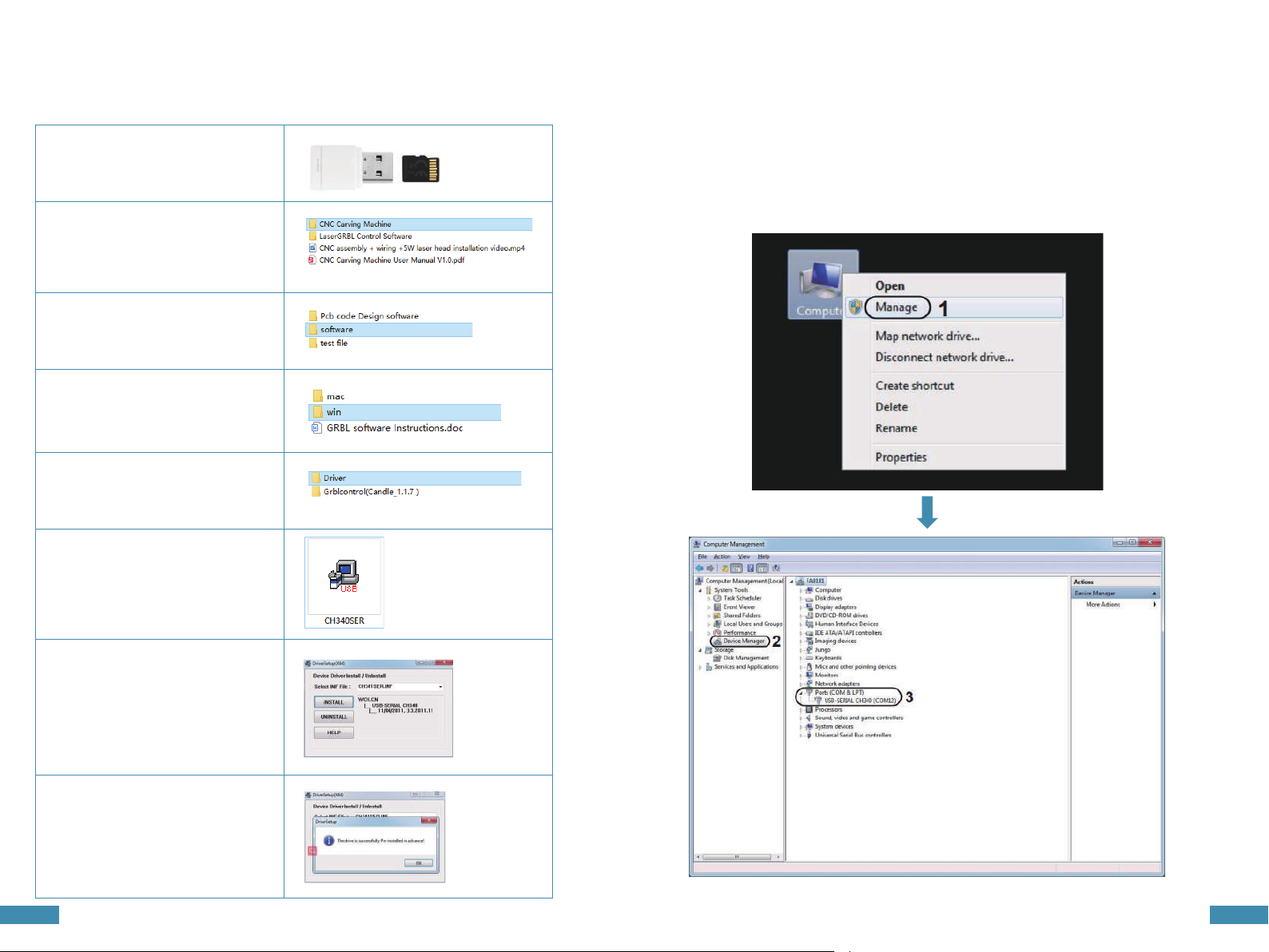
For related installation files, please check: https://www.comgrow.com
Join our Facebook support group: https://www.facebook.com/groups/comgrow/
WELCOME TO COMGROW!
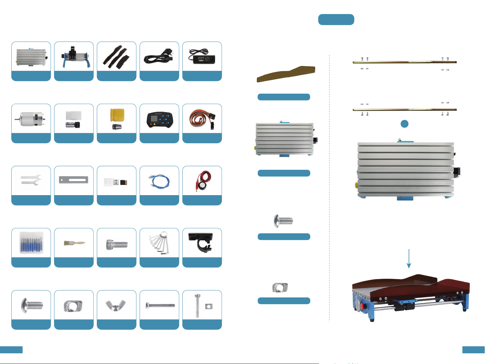
Product exterior size 400*275*268mm(motor not included)
Characteristics
Milling size 300*180*45mm
Weight 7.5KG
Drive motor 42 stepper motor,0.48 N.m.
Spindle 775 motor, 12V~24V,10000RPM
System Windows XP, Windows 7 32/64 bits,
Windows 8, Windows 10, Linux system.
Composed of aluminum, the overall structure is stable to meet the
needs of milling a wider range of materials; available for engraving
and cutting wood, plastic, acrylic, PCB, soft aluminum and so on;
unavailable for hard metals, jade and other hard objects
Acrylic baffle prevents from dust and make it easier to clean up;
equipped with emergency stop button, stop milling with one press
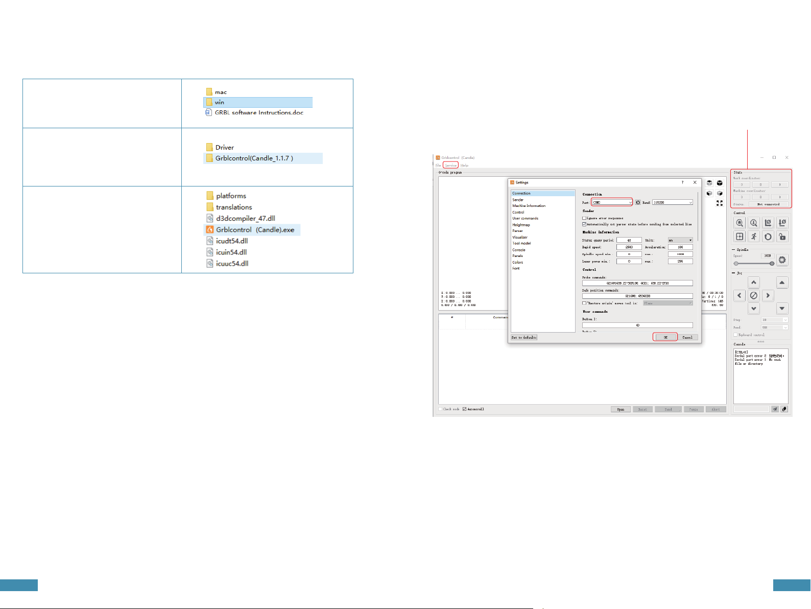
Operating by GRBL software or offline control handle;