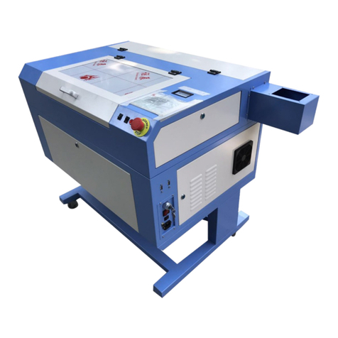
GRAVOGRAPH LS100 V1 User manual

NOTICE TECHNIQUE LS100
LS100 TECHNICAL MANUAL
Date : June 2009 From
After ale Technical Support
Ref. LS100 GB/FF - Ver . 1.0
Page 1
Servicing Manual
Manuel Technique
LS100 machine V1 & V2
Machine LS100 V1 et V2
English – French
September 2011 from After Sale Technical Support

NOTICE TECHNIQUE LS100
LS100 TECHNICAL MANUAL
Date : June 2009 From
After ale Technical Support
Ref. LS100 GB/FF - Ver . 1.0
Page 2
SUMMARY - SOMMAIRE
LS100-01 SPARES PART LIST - LISTE PIECES DETACHEES --------------------- page : 04
UPDATED
MAINTENANCE PROCEDURES - PROCEDURE DE MAINTENANCE
LS100-02 = TOP DOOR V1 - PORTE SUPERIEUR V1 ------------------------------- page : 07
LS100-02 V2 = TOP DOOR V2 - PORTE SUPERIEUR V2 -------------------------- page : 09
UPDATED
LS100-03 = DOOR DETECTORS - DETECTEUR DE PORTE ----------------------- page : 11
LS100-04 = ENGRAVING TA LE – TABLE DE GRAVURE---------------------------- page : 14
LS100-05 = X GUIDING – GUIDAGE X--------------------------------------------------- page : 17
UPDATED
LS100-06 = X MOTOR - MOTEUR X ---------------------------------------------------- page : 20
LS100-07 = X LIMIT SWITCH - FIN DE COURSE X ----------------------------------- page : 24
LS100-08 = X ELT – COURROIE X ------------------------------------------------------- page : 28
LS100-09 = HEAD MIRROR – MIROIR DE TETE--------------------------------------- page : 32
LS100-10 = Y MOTOR - MOTEUR Y ---------------------------------------------------- page : 33
LS100-11 = Y LIMIT SWITCH - FIN DE COURSE Y ----------------------------------- page : 39
LS100-12 = Y MOTOR ELT – COURROIE MOTEUR Y------------------------------ page : 42
LS100-13 = Y ELT – COURROIE Y ------------------------------------------------------- page : 46
LS100-14 = Y ELT TENSION ELT – SYSTEM DE TENSION COURROIE Y------ page : 50
LS100-15 = Z LIMIT SWITCH - FIN DE COURSE Z ----------------------------------- page : 53
LS100-16 = Z AUTO LIMIT SWITCH – FIN DE COURSE AUTO Z------------------- page : 55
LS100-17 = Z AUTO-FOCUS AR – BARRE AUTO-FOCUS -------------------------- page : 58
LS100-18 = Z MOTOR – MOTEUR Z ----------------------------------------------------- page : 61
LS100-19 = Z ELT – COURROIE Z-------------------------------------------------------- page : 65
LS100-20 = TA LE LEADSCREW – VIS Z DE TABLE ---------------------------------- page : 67
LS100-21 = RIGHT MIROR ON THE RIDGE- MIROIR DE DROITE PONT ------ page : 73
LS100-22 = ELECTRONIC RACK - RACK ELECTRONIQUE--------------------------- page : 75
LS100-23 = ON /OFF SWITCH - INTERRUPTEUR MARCHE ARRET------------- page : 80
LS100-24 = LASER TU E POWER SUPPLY – ALIMENTATION TUBE LASER --- page : 82
UPDATED
LS100-25 = CPU OARD – CARTE UC --------------------------------------------------- page : 88
LS100-26 = SAFETY OARD – CARTE SECURITE-------------------------------------- page : 90
LS100-27 = LASER TU E – SOURCE LASER -------------------------------------------- page : 93
UPDATED
LS100-28 = POWER OARD – CARTE PUISSANCE ----------------------------------- page : 103
LS100-29 = LASER INTERFACE OARD - CARTE INTERFACE LASER ------------ page : 106
UPDATED
LS100-30 = LASER CONTROL OARD – CARTE LASER CONTROL---------------- page : 110
UPDATED
LS100-31 = CONTROL PANEL – CLAVIER DE COMMANDE------------------------ page : 113
LS100-32 = ELECTRICAL FILTER - FILTRE ENTREE SECTEUR ----------------------- page : 115
LS100-33 = CYLINDER ATTACHMENT OARD - CARTE TC------------------------ page : 117
LS100-34 = REPLACING LAMPLIGHTING – CHANGE. PLATINE ECLAIRAGE--- page : 120
NEW
LS100-35 = REPLACING THE LAMP – CHANGE. DE L’AMPOULE----------------- page : 122
NEW
NOTICE TECHNIQUE LS100
LS100 TECHNICAL MANUAL
Date : June 2009 From
After ale Technical Support
Ref. LS100 GB/FF - Ver . 1.0
Page 3
ADJUSTMENT PROCEDURES - PROCEDURE DE REGLAGE
LS100-A01 = FLATNESS ADJUSTMENT – REGLAGE PLANEITEE------------------ page : 124
LS100-A02 = LASER EAM ADJUSTMENT – REGLAGE FAISCEAU LASER ----- page : 126
LS100-A03 = RED POINTER ADJUSTMENT – REGLAGE POINTEUR ROUGE -- page : 136
LS100-A04 = Z FOCAL ADJUSTMENT – REGLAGE FOCUS Z --------------------- page : 139
LS100-A05 = LEFT CORNER ADJUSTMENT – REGLAGE POINT ZERO----------- page : 142
LS100-A06 = TICKLE ADJUSTMENT - REGLAGE TICKLE---------------------------- page : 144
UPDATED
LS100-A07 = ALIGNMENT MODE – MODE ALIGNEMENT ------------------------ page : 148
CHARACTERISTICS – CARACTERISTIQUES
LS100-T01 = CHARACTERISTIC - CARACTERISTIQUES ------------------------------ page : 150
LS100-T02 = FIRMWARE MENU – MENU FIRMWARE ----------------------------- page : 155
UPDATED
TROUBLES SHOOTING - DISFONCTIONNEMENTS
LS100-TS01 = TROU LES SHOOTING WITH ERROR MESSAGES
PROBLEMES TECHNIQUE AVEC MESSAGE D’ERREUR
1 MOTOR OVER TEMPS – 1 TEMPERATURE MOTEUR........ page : 162
UPDATED
2 POWER SUPPLY – 2 ALIM LASER .................................... page : 167
UPDATED
03 LASER OVER TEMP – 3 TEMP LASER ............................... page : 168
UPDATED
04 LASER FAULT – 3 DEFAUT LASER .................................... page : 168
UPDATED
LS100-TS0 = TROU LES SHOOTING WITHOUT ERROR MESSAGES
PROBLEMES TECHNIQUE SANS MESSAGE D’ERREUR ---------- page : 169
NEW

NOTICE TECHNIQUE LS100
LS100 TECHNICAL MANUAL
Date : June 2009 From
After ale Technical Support
Ref. LS100 GB/FF - Ver . 1.0
Page 4
LS100 - 01 - SPARE PARTS LIST - LISTE DES PIECES DETACHEES
Part number
/ References
Designation / Désignation
Initial stock for 20
machines sold /
Stock recommanded
pour 20 vendues
10016
HEXAGONAL KEY 2mm
11716
SPARER BAR
12113
BEARINGS
12435
HOSTAFORM BALLS
13371
RUBBER FOOT
14143
POLYURETHANE PIPE diam: 4mm 2
14247
Y LINEAR BEARING
14338
MALE CONE diam: 15-75mm
14463
PARALLEL CABLE MINI SUB-D IS-LS
14599
PNEUMATIC CONNECTOR 4mm/4mm
14792
I/O CABLE LE150 EXHAUST SYSTEM - COMPRESSOR
14877
MALE STRAIGHT FITTING M5 diam: 4mm
15240
FLOW REGULATOR 1
15280
LASER CONTROL BOARD SYNRAD
15327
I/O CABLE EXHAUST SYSTEM
15332
Y STEPPER MOTOR SIMPLE SHAFT
15352
20-40-60W T60 INTERFACE BOARD
22930
LCD SCREEN KIT
23542
X Y AXIS SLEEVE
24297
LS 30 LENS COTTON BUD WALLET
26327
CLEANING KIT G1/G2 1
26530
LASER SAFETY GLASSES 1
26554
LASER POWER METER 1
27379
2.5 INCHES FOCAL LENS KIT G1V3/G2
27381
3.5 INCHES FOCAL LENS KIT G1V3/G2
27382
4 INCHES FOCAL LENS KIT G1V3/G2
28756
Y BELT 260mm LS100/700/800/900 1
28854
FILTER IEC INLET 16A
28855
SWITCH ON/OFF WITH INTERNAL CIRCUIT 1
29277
OPTIC ADJUSTMENT TARGET 1
29281
24V RELAY
29289
1.5 INCH FOCAL ROD
29307
FLEXIBLE SENSOR KIT V3 2
29310
AIR DUCT COUPLING – 100/100 (4”)
29311
AIR DUCT REDUCER – 100/125 (2”)
29314
FAN KIT 80x80mm – G2
29315
SAFETY BOARD KIT G2
29393
LASER TUBE 30W WIRING
29394
SYNRAD 30W INTERFACE BOARD 1
29834
CYLINDER ATTACHMENT GUIDE
29836
REVOLUTION SHAFT CYLINDER ATTACH.
30446
STEPPER MOTOR CYL. ATT
36936
CYLINDER ATTACHMENT BOARD G2
39139
ASPIRATION PIPE diam: 100mm

NOTICE TECHNIQUE LS100
LS100 TECHNICAL MANUAL
Date : June 2009 From
After ale Technical Support
Ref. LS100 GB/FF - Ver . 1.0
Page 5
41270
MICROSWITCH WITH CONNECTOR 2
42035
ELECTRONIC FAN KIT
42120
STD EXC CA CONTROL BOARD - OBSOLETE
45667
STD EXC LASER POWER BOARD KIT OBSOLETE
45698
USB 2.0 CABLE 2 Meters
45948
CYL. ATT. MOTOR AND JAW KIT W/OUT BOARD
46174
AIR ASSIST KNOB 3
46189
DOOR MAGNET
46193
ELASTOMER KEYPAD
46194
LS100 KEYBOARD CASE FRONT
46195
X RULE
46196
Y RULE
46197
NUT RULE
46203
X Y BELT ATTACHMENT 4
46211
X BELT 1
46212
Y BELT 2
46224
X LINEAR GUIDEWAY
46225
AUTOFOCUS RULE
46252
AIR ASSIST COPPER PIPE
46253
BEAM COMBINER MIROR
46258
SYNRAD SOURCE CASE
46259
30W LASER TUBE POWER SUPPLY
46260
Y MOTOR DOUBLE SHAFT KIT OBSOLETE
46261
ELECTRONIC RACK WIRING LOOM
46262
MACHINE WIRING LOOM
46263
INTERFACE DISPLAY BOARD
46265
CABLED DOOR SENSOR 1
46373
UC USB BOARD 32Mo 1
46559
OBSOLET STD EXC UC USB BOARD 32Mo OBSOLETE
46981
2 INCH FOCAL ROD LASER 1
47003
LS100 SEAL DOOR KIT
47081
HONEYCOMB CUTTING TABLE
47082
LENS KIT 1.5 INCH
47192
30W ELECTRONIC RACK
47193
ASSEMBLY KEYPAD KIT 1
47194
30W LASER SOURCE
47195
DAMPER KIT
47196
FITTED ENGRAVING TABLE KIT
47197
OPTICAL BLOCK KIT
47198
RED POINTER KIT WITH HOLDER 1
47199
Z LEADSCREW KIT
47200
2 INCHES LENS KIT 1
47201
HEAD MIRROR & BRACKET KIT 3
47202
RIGHT MIRROR & BRACKET KIT 3
47203
RIGHT Y BELT TENSIONNING IDLER KIT
47204
LEFT Y BELT TENSIONNING IDLER KIT
47205
X MOTOR WITH PULLEY KIT ONE SHAFT
47206
Z MOTOR WITH PULLEY KIT
47254
STD EXC ELECTRONIC RACK KIT 30W & 40W
47255
STD EXC ASSEMBLY KEYPAD
47256
STD EXC 30W LASER SOURCE KIT

NOTICE TECHNIQUE LS100
LS100 TECHNICAL MANUAL
Date : June 2009 From
After ale Technical Support
Ref. LS100 GB/FF - Ver . 1.0
Page 6
47308
LE140 CARBON FILTER 40L
47309
LE120 CARBON FILTER 20L
47310
LE 140 6 PLEADS PREFILTER
47311
LE 120 3 PLEADS PREFILTER
47312
SOLENOID VALVE KIT
47471
DAMPER
47562
55W LASER TUBE POWER SUPPLY – 1 BLOCK
47563
55W LASER SOURCE INTERFACE BOARD
47597
LEFT INSIDE CASING KIT
47598
RIGHT INSIDE CASING KIT
47600
24V RELAY
47729
Z HOLDER BEARING
47774
X MOTOR WITH PULLEY KIT DAMPER VERS. 2 SHAFTS 2
47799
STD EXC 55W ELECTRONIC RACK
47800
STD EXC 55W LASER SOURCE
47837
55W LASER SOURCE CASING
47838
55W ELECTRONIC RACK KIT
47904
USB CABLE 3.5 Meters
48003
LE120/140 EXHAUST CONTROLLER BOARD
48530
LASER POWER BOARD G3 1
48696
MIRROR SUPPORT CALIPER MACHINE
48894
AUTO FOCUS Z AXIS LS100 KIT 2
48943
HEAD SUPPORT LS100
49056
Y MOTOR RETROFIT KIT
49097
PRESEPARATOR REPLACEMENT BAG
49113
COMPLETE WIRING LOOM (RACK+MACHINE)
49296
DOOR KIT
49618
40W ELECTRONIC RACK KIT
49725
LASER CONTROL BOARD 1
49893
LE120/140+ 230V TURBINE
49894
LE120/140+ 115V TURBINE
49895
LE120/140HP 230V TURBINE
49896
LE120/140HP 115V TURBINE
49998
CYLINDRICAL ATTACHMENT SWIVEL AXIS KIT
50121
NEW LS100 V2 DOOR
51771
X Y RULES KITS
52199
STD EXC 40W LASER TUBE KIT - SYNRAD
56305
LASER TUBE FAN KIT – 30W – 40W
58884
DIODE KIT POWER SUPPLY 1
61995
LASER FAN BOARD KIT
62757
STD EXH 60W LASER TUBE KIT - COHERENT
62916
2.5” LENS LASER KIT
64839
INTERFACE BOARD SYNRADE&COHERENT COMPATIBLE
64948
CO² & YAG LASER SAFETY GOGGLE
66153
BEAM FOAM SEAL
66607
HONETCOMB CUTTING TABLE “INCH” -LS100
67013
DOOR V2 AXES KIT
68953
CA REDUCTION KIT
66231
STD EXC 35W LASER TUBE KIT - COHERENT
66235
STD EXC 40W LASER TUBE KIT - COHERENT

NOTICE TECHNIQUE LS100
LS100 TECHNICAL MANUAL
Date : June 2009 From
After ale Technical Support
Ref. LS100 GB/FF - Ver . 1.0
Page 7
OPERATION: LS100-02
REPLACING THE TOP DOOR - CHANGEMENT DE LA PORTE SUPERIEURE
Dismantling operation - Opération de démontage
Open the top door, unscrew the right and left axis but do not
remove them
Ouvrir la porte supérieure, Desserrer l’axe droit et gauche sans
les retirer.
Move the right axis towards inside in order to separate it from
the frame.
Faire glisser l’axe droit vers l’intérieur pour le dissocier du bâti.
Move the left axis towards inside in order to separate it from
the frame.
Faire glisser l’axe gauche vers l’intérieur pour le dissocier du
bâti.
To slide the axis door easier, lift up lightly the door.
Pour déplacer les axes facilement, il est utile de soulever légèrement la
porte.
Remove the top door by lifting it up lightly and by sliding it .
Retirer la porte en la soulevant légèrement et en l’inclinant.
Warning, the 2 springs will untie from their supports but this is
normal.
Attention, les 2 ressorts de rappel vont se détacher de leurs
supports, c’est normal.
Part number:
TOP DOOR KIT : O SOLETE = NEW DOOR 50121

NOTICE TECHNIQUE LS100
LS100 TECHNICAL MANUAL
Date : June 2009 From
After ale Technical Support
Ref. LS100 GB/FF - Ver . 1.0
Page 8
Reassembling operation - Opération de remontage
Put the door on the blanks with space between the door and frame
machine in order to put back the spring.
Poser la porte sur les flans de la machine en laissant un espace pour
la remise en place des ressorts.
Place the left and right ways spring into the springs
Placer les axes de guidage droit et gauche dans les ressort
Place the door correctly by lifting it up and by pushing towards the
bottom.
Placer la porte correctement en la soulevant légèrement et en la
poussant vers le fond.
Insert the left and right axis into the frame.
Glisser maintenant les axes droit et gauche dans le bâti.
Tight the screw of each axis.
Resserrer la vis de chaque axe.
This operation is finished, Check the opening and closing of the door.
Opération terminée, vérifier la bonne ouverture et fermeture de la porte

NOTICE TECHNIQUE LS100
LS100 TECHNICAL MANUAL
Date : June 2009 From
After ale Technical Support
Ref. LS100 GB/FF - Ver . 1.0
Page 9
OPERATION: LS100-02 V2
REPLACING THE TOP DOOR V2 - CHANGEMENT DE LA PORTE SUPERIEURE V2
Dismantling operation - Opération de démontage
Open the top door, unscrew the right and left axis but do not
remove them
Ouvrir la porte supérieure, Desserrer l’axe droit et gauche sans
les retirer.
Move the right axis towards inside in order to separate it from
the frame.
Faire glisser l’axe droit vers l’intérieur pour le dissocier du bâti.
Move the left axis towards inside in order to separate it from
the frame.
Faire glisser l’axe gauche vers l’intérieur pour le dissocier du
bâti.
To slide the axis door easier, lift up lightly the door.
Pour déplacer les axes facilement, il est utile de soulever légèrement la porte.
Remove the top door by lifting it up lightly and by sliding it .
Retirer la porte en la soulevant légèrement et en l’inclinant.
Warning, the 2 springs will take off from their supports but this is normal.
Attention, les 2 ressorts de rappel vont se détacher de leurs supports, c’est normal.
Part number:
TOP DOOR KIT : 50121

NOTICE TECHNIQUE LS100
LS100 TECHNICAL MANUAL
Date : June 2009 From
After ale Technical Support
Ref. LS100 GB/FF - Ver . 1.0
Page 10
Reassembling operation - Opération de remontage
Put the door on the blanks with space between the door and frame
machine in order to put back the spring.
Poser la porte sur les flans de la machine en laissant un espace pour
la remise en place des ressorts.
Place the left and right ways spring into the springs
Placer les axes de guidage droit et gauche dans les
ressorts.
Place the door correctly by lifting it up and by pushing towards the
bottom.
Placer la porte correctement en la soulevant légèrement et en la
poussant vers le fond.
Insert the left and right axis into the frame, and
then tighten the screws, to lock shafts.
Glisser maintenant les axes droit et gauche dans
le bâti puis serrer les vis de blocages.
This operation is finished, Check the opening and closing of the door.
Opération terminée, vérifier la bonne ouverture et fermeture de la porte

NOTICE TECHNIQUE LS100
LS100 TECHNICAL MANUAL
Date : June 2009 From
After ale Technical Support
Ref. LS100 GB/FF - Ver . 1.0
Page 11
OPERATION: LS100-03
REPLACING THE DOOR SENSOR - CHANGEMENT DES DETECTEURS DE PORTE
Dismantling operation (right and left side)
Opération de démontage (droit et gauche)
Before this operation, we recommend to move down the table in order to
ease the access to the different elements.
Avant de procéder à cette opération, nous vous conseillons de descendre
légèrement la table afin de facilité l’accès aux différents éléments.
Unscrews the 4 screws located inside the machine.
Desserrer les 4 vis placées à l’intérieur de la machine.
Remove the front plate by lifting it up.
Retirer la tôle avant en la soulevant.
Right side sensor - Detecteur coté droit
•Disconnect the wiring looms to take care of unlocked the connectors.
•
Déconnecter le connecteur du détecteur de porte en ayant pris soin de
déverrouiller le verrou.
•
Remove the sensor holder by 2 fixing screws
•
Démonter le support de détecteur en retirant les 2 vis de fixation Enlever
ensuite le détecteur de porte
•Remove the door sensor from its plate holder by 2 screws.
•
Enlever le capteur de son support par les 2 vis.
Part number: CA LED DOOR SENSOR KIT: 46265

NOTICE TECHNIQUE LS100
LS100 TECHNICAL MANUAL
Date : June 2009 From
After ale Technical Support
Ref. LS100 GB/FF - Ver . 1.0
Page 12
Left side sensor - Detecteur coté Gauche
•Disconnect the wiring looms to take care of unlocked the connectors.
•
Déconnecter le connecteur du détecteur de porte en ayant pris soin de
déverrouiller le verrou.
•Remove the door sensor from its plate holder by 2 screws.
•
Enlever le capteur de son support par les 2 vis.
Assembling operation - Opération de remontage
Right side sensor - Detecteur coté droit
Place the sensor on its holder, to the limit plate (as indicated on picture),
then use the 2 screws to fix it
Repositionner le détecteur en limite de support, puis
le fixer à l’aide des 2 vis
Place the sensor and its holder on machine, then use the 2 screws to fix it
Repositionner le détecteur en limite de support, puis
le fixer à l’aide des 2 vis
•Reconnect the 2 connectors.
•
Reconnecter les 2 connecteurs.

NOTICE TECHNIQUE LS100
LS100 TECHNICAL MANUAL
Date : June 2009 From
After ale Technical Support
Ref. LS100 GB/FF - Ver . 1.0
Page 13
Left side sensor - Detecteur coté gauche t
Place the right door sensor in the limit of the plate holder in order to assure a
right detection.
Repositionner le détecteur de porte en limite de la plaque support afin
d’assurer une bonne détection.
•Tight the 2 screws of the right door magnet.
•
Serrer les 2 vis de l’aimant de porte.
•Reconnect the 2 connectors.
•
Reconnecter les 2 connecteurs.
•Replace the front plate.
•
Replacer la tôle avant.
•
Tight the 4 screws located inside the machine.
•Resserrer les 4 vis placées à l’intérieur de la machine.
This operation is finished, switch on the machine in order to verify that the initialization
do not show any message of the door detection like “Door open” .
If “Door open” is showing on display, you have to adjust the door sensors
Opération terminée, mettre en marche la machine afin de vérifier que l’initialisation du
firmware ne fait pas apparaître un message d’erreur pour la détection de la
porte. «Porte ouverte »
Si le message « Porte ouverte » apparaît à l’écran LCD, il faut alors ajuster les
détecteurs de porte

NOTICE TECHNIQUE LS100
LS100 TECHNICAL MANUAL
Date : June 2009 From
After ale Technical Support
Ref. LS100 GB/FF - Ver . 1.0
Page 14
OPERATION: LS100-04
REPLACING THE ENGRAVING TABLE - CHANGEMENT DE LA TABLE DE GRAVURE
Dismantling operation - Opération de démontage
Before starting this operation, we recommend you to move down the engraving table to the bottom
position.
Pour cette opération nous vous conseillons de descendre la table de gravure en position basse.
Remove the right and left side of the machine by
2 screws.
Retirer la tôle droite et gauche de la machine par
les 2 vis.
To loosen the table screws, lock the bottom Screw with a flat
spanner (17mm) then to loosen the top Screw.
Pour desserrer les écrous de table, bloquer l’écrou inferieur
avec une clé (17mm) puis desserrer l’écrou supérieur.
oRepeat this operation for the 2 other Z screws of the engraving
table.
o
Répéter l’opération pour les 2 autre vis de table de gravure.
To make easier the dismantling of the engraving table, slide up the brass
screw, rubber washer and brass washer to the top of the screw. Fix them
with a piece of tape.
Afin de facilité le démontage de la table, remonter l’écrou, le joint torique et
la rondelle en laiton en haut de la vis. Fixer l’ensemble avec un morceau
d’adhésif.
Part number:
COMPLETE ENGRAVING TA LE : 47196

NOTICE TECHNIQUE LS100
LS100 TECHNICAL MANUAL
Date : June 2009 From
After ale Technical Support
Ref. LS100 GB/FF - Ver . 1.0
Page 15
Lift the table up by the right side and pull it slightly to the right to take it
out of the machine.
Soulever la table par le coté droit, la tirer légèrement vers la droite puis
la sortir de la machine.
Reassembling operation - Opération de remontage
To place back the engraving table, tilt it and insert the table support
openings in the screws.
Pour replacer la table de gravure, incliner la vers la gauche et insérez les
lumières des supports de table dans les écrous.
To place back the right side of the engraving table on the brass screw.
Replacer le coté droit de la table de gravure sur l’écrou de la vis guide.
In order to make easier the flatness adjustment of the table, we suggest you
to make a preliminary adjust of the brass screws.
Afin de faciliter le réglage de planéité de la table, nous vous conseillons de
procéder à un réglage de planéité préliminaire des écrous.
Place the focal rod between the bottom of the frame and the bottom part
of the screw. This distance will be the same for the 4 screws.
Placer la pige de réglage focus entre le fond du bâti et la partie inférieure
de l’écrou. Ceci vous permettra d’avoir une distance égale sur les 3
écrous de la table de gravure.
Put “Nutlock” on the bottom nuts/screw.
Mettre un peu de frein filet sur l’écrou/vis inférieur.
Tight the top screw by hand up to get a slight compression on the rubber
washer.
Serrer l’écrou supérieur à la main jusqu’à compresser légèrement le joint
torique. Le support de table ne doit plus bouger.

NOTICE TECHNIQUE LS100
LS100 TECHNICAL MANUAL
Date : June 2009 From
After ale Technical Support
Ref. LS100 GB/FF - Ver . 1.0
Page 16
Repeat this operation for the 2 other Z screws. Be sure to respect the distance with
the focal rod. Let “Nutlock” to dry few minutes.
Répéter l’opération pour les 2 derniers écrous. Respecter la distance de focale.
Laisser sécher quelques minutes.
Make the flatness adjustment of the engraving table = see chapter LE100-34
Procéder au réglage de planéité de la table = voir chapitre LE100-34)
Put back the right and left sides of the machine
by 2 screws.
Remettre la tôle droite et gauche de la machine
par les 2 vis.
This operation is finished; make an engraving test by using the complete area of the
engraving table.
Opération terminée, faire un essai de gravure en utilisant la surface complète de la table de
gravure.

NOTICE TECHNIQUE LS100
LS100 TECHNICAL MANUAL
Date : June 2009 From
After ale Technical Support
Ref. LS100 GB/FF - Ver . 1.0
Page 17
- NEW -
OPERATION: LS100-05
REPLACING THE X LINEAR GUIDEWAY - CHANGEMENT DU GUIDAGE X
A new quick way to replace the X guide without to remove without to the X belt .
WIthout to lacken the X belt
Une nouvelle procédure, plus rapide pour chan er le uida e X sans déposer la courroie X
Sans avoir à détendre la courroie X
Dismantling operation - Opération de démontage
Put the head on the right side of the bridge and remove the guiding screws
on left side….
Positionner la tête en position gauche sur le pont, puis déposer les vis de
droite du guidage….
… and then put the head on the left side to remove the screw which are
on the right. Keep the center screw for the moment
… puis déplacer la tête à gauche du pont pour déposer les vis de droite,
laisser la vis centrale pour le moment.
Put the head in the center of the X guide way, and
the remove the 2 screws used to fix the head on
the guide.. and then remove the head from guiding
Positionner la tête au centre du guidage, puis
déposer les 2 vis de la tête utilisée pour fixer la tête
sur le guidage, puis déposer la tête.
You can now remove the center screw of the X guiding, and
then remove the guiding from the bridge.
Vous pouvez maintenant déposer la vis centrale du guidage,
puis déposer le guidage du pont X
Part number:
X LINEAR GUIDE : 46224

NOTICE TECHNIQUE LS100
LS100 TECHNICAL MANUAL
Date : June 2009 From
After ale Technical Support
Ref. LS100 GB/FF - Ver . 1.0
Page 18
Reassembling operation - Opération de remontage
When you receive a new X linear guide, there are 2 top carriage to each extremities,
you must remove them before to put the guide on the bridge, but attention to keep the
guide in horizontal position in order to avoid to make fall the carriage, il the carriage is
removed from the guide, the guiding will be useless.
Quand vous un nouveau guide X, il y a 2 cavaliers à chaque extrémités. Vous devez les
retirer avant l’installation du guidage sur le pont. Mais attention de maintenir le guide
en position horizontale afin d’éviter de faire tomber le chariot mobile. Si le chariot est
retiré du guidage, il sera inutilisable.
Put back the new X guide way on the bridge, and
then put all fixing screws without tightening.
Replacer le nouveau guidage sur le pont, puis
mettre en place toute les vis de fixation sans les
serrer.
Put the head on the carriage, and fix it with 2 screws without lock them
Positionner la tête sur le chariot, puis la fixer au guidage à laide des 2 vis
sans les serrer
Put the head on right side, lift the X guide way up and tight the first left
screw.
Positionner la tête à droite, puis soulever le guidage et serrer la
première vis à gauche.
Put the head on left side, lift the X guide way up and tight the first right
screw.
Positionner la tête à gauche, puis soulever le guidage et serrer la
première vis à droite.
Tighten the central screw, and then all the other screws of the guide
Serrer la vis centrale puis toutes les autres vis du guidage.

NOTICE TECHNIQUE LS100
LS100 TECHNICAL MANUAL
Date : June 2009 From
After ale Technical Support
Ref. LS100 GB/FF - Ver . 1.0
Page 19
You must now tighten the 2 head screws.
Vous devez maintenant serrer les 2 vis de la tête.
Check the flatness table and adjust it if necessary = See chapter LS100-034.
Contrôle de planéité table, ajuster si nécessaire = Voir chapitre LS100-034.
This operation is finished; make an engraving test by using the complete area of the
engraving table.
Opération terminée, faire un essai de gravure en utilisant la surface complète de la table de
gravure.

NOTICE TECHNIQUE LS100
LS100 TECHNICAL MANUAL
Date : June 2009 From
After ale Technical Support
Ref. LS100 GB/FF - Ver . 1.0
Page 20
OPERATION: LS100-06
REPLACING THE X MOTOR - CHANGEMENT DU MOTEUR X
When you have to replace a X stepper motor, you must replace the complete
Kit :Motor + pulley which is adjusted to the factory (concentricity pulley shaft
motor: 0.1mm)
Quand vous procédez à l’échange du moteur X, vous devez changer le Kit
complet : Moteur + poulie, qui sont ajustés en usine (concentricitée poulie /axe
moteur .1mm).
Dismantling operation - Opération de démontage
Remove the right side casing 4 nuts.
Retirer le carter droit par ses 4 vis.
Remove the left side of the machine by 2 screws in
order to remove the X belt = See chapter LS100-
08.
Retirer la tôle gauche de la machine par les 2 vis
afin de retirer la courroie X = voir chapitre LS100-
08.
Unscrew the 2 screws of keyboard plate support
and move it to access to the stepper motor.
Desserrer Les 2 vis de la plaque de maintien du
clavier et le décaler pour accéder au moteur.
Move forward the X Bridge.
Déplacer the pont X vers le devant de la machine.
P/N:X MOTOR WITH PULLEY & DAMPER
–
MOTEUR AVEC POULIE ET DAMPER
: 47774
This manual suits for next models
1
Table of contents
Other GRAVOGRAPH Engraver manuals

GRAVOGRAPH
GRAVOGRAPH UNICA TX User manual

GRAVOGRAPH
GRAVOGRAPH M20 PIX User manual

GRAVOGRAPH
GRAVOGRAPH LS1000 XP Operating instructions

GRAVOGRAPH
GRAVOGRAPH L-SOLUTION 100 Ex Fibre User manual

GRAVOGRAPH
GRAVOGRAPH M40 Vice User manual

GRAVOGRAPH
GRAVOGRAPH LS100 IQ Operating instructions

GRAVOGRAPH
GRAVOGRAPH LS900 XP Operating instructions