Diablo Controls DSP-222 User manual

DSP222H_Manual_A Page 1 of 17
DSP-222 Operations Manual
Dual Channel Inductive
Loop Detector Sensor Unit
This manual contains technical information for the DSP-222 detector sensor unit.
Included are general description, general characteristics, installation procedure,
adjustment instructions, operational guide, maintenance procedures and technical
schematics and drawings.

DSP222H_Manual_A Page 2 of 17
1. General Description
The DSP-222 is a dual-channel inductive loop vehicle detector sensor unit designed to
meet the State of California, Department of Transportation, (Caltrans) specification
TSCES dated January of 1989 and the addendum dated July of 1991.
2. General Characteristics
The sensor unit incorporates a double-sided 44-pin edge connector for the connection
of power, loop inputs and call outputs and sensor unit reset. Each channel has
individual front-panel controls for setting sensitivity, frequency, and pulse/presence
mode. Each channel is also equipped with two high-intensity front-panel LEDs which
are used to indicate the detect state and fail condition of the individual channels. Call
outputs are optically isolated solid-state transistors. The sensor unit occupies one
position of a standard 170 input file. Each channel of the DSP-222 will automatically
tune to any loop and lead-in inductance between 50 and 750 microhenries with a loop
system “Q” as low as 5. The unit will detect inductance changes as small as 0.01%
∆L/L.
3. Installation and Adjustments
The sensor unit is factory shipped with all switches set to off signifying both channels
are disabled. The MIN PRESENCE jumper J1 located on the printed circuit board is
installed forcing all detection outputs to last a minimum of 100 ms in the presence
mode. The ALTERNATE jumper J2 located on the printed circuit board is installed
forcing both channels to operate in the non-scanning mode.
a) Remove the MIN PRESENCE jumper J1 on the circuit board to allow presence
outputs of times less than 100 ms, if so desired.
b) Remove the ALTERNATE jumper J2 on the circuit board to allow both channels to
scan sequentially, if so desired.
c) Make sure that the sensor unit is firmly seated into its position in the input file.
d) Set the PULSE switch on for pulse operation. Set the PULSE switch off for presence
operation.
e) Adjust sensitivity by setting switches S1, S2, and S4 to the desired position using
standard binary coding. Sensitivity 1 is the lowest setting and Sensitivity 7 is the highest

DSP222H_Manual_A Page 3 of 17
setting. If a channel is not used, it may be switched off (disabled) by setting it to
Sensitivity 0 (all three switches off).
f) Frequency setting needs to be changed only if crosstalk occurs between nearby
loops. Crosstalk usually manifests itself as chattering of the call output. Change the
frequency if crosstalk is encountered. Four frequency positions are available on each
channel to assist in alleviating interference. It may be necessary to reset the channel
after the frequency has been changed.
g) Check the front-panel indicators. If the Fault LEDs on either channel are flashing
there is a problem with the loop system on that channel. Observe the flash sequence to
determine the type of fault. A single flash followed by a pause indicates an open loop
system. A double flash indicates a shorted loop system. Check the loop connections
carefully. Reset both channels by momentarily selecting a different sensitivity or mode
and then return to the original setting.
h) Monitor operation and make adjustments to the sensitivity and frequency as
necessary.
4. Theory of Operation
The DSP-222 works on the principle that loop frequency is directly related to loop
inductance. However, the change in loop frequency is very small -- perhaps as little as
one hertz. It is easy to measure a change of one hertz simply by counting the number of
cycles in one second. Unfortunately, the minimum response time using this method is
easily greater than one second. To improve the response time, the measurement is
done by gating a high-speed stable oscillator with the loop frequency. This scheme,
called period measurement, provides high-resolution in a short period of time. This
measurement is compared to a previously established reference to determine whether
or not the frequency of the loop oscillator has changed sufficiently to indicate the
presence of a vehicle.
The high speed of the reference crystal oscillator ensures that the sample can be taken
within a very short period of time. For example, at sensitivities less than 4, a sample can
be taken within 2 ms which allows the sensor unit to respond to a vehicle presence (or
loss of presence) in the detection area with an accuracy of 1 ms. Note: This is true only
if the ALTERNATE jumper J2 is installed.
Sensitivity is a function of how long a sample is used for the determination of a vehicle
presence, i.e. the longer the sample time, the more sensitive the sample. Since the
sensor unit measures the minute changes in loop oscillations, it follows that low
frequency loops are innately more sensitive than high frequency loops. In order to keep

DSP222H_Manual_A Page 4 of 17
the sensitivity the same over the wide spectrum of loop frequencies, the sensor unit first
measures the loop frequency and calculates the number of complete cycles needed for
a sample. This value is then used for all subsequent loop measurements for this
channel.
The sensor unit checks the completed sample to confirm that it is still within acceptable
operating limits and then determines whether the sample has changed sufficiently with
respect to the stored reference to indicate the presence of a vehicle. It then controls the
output and indicators appropriately. Minor changes in period occurring over a relatively
long time are due entirely to environmental fluctuations. By altering the stored reference
slowly, these environmental changes are ignored. In this fashion, the sensor unit can
compensate for temperature changes and other long-term effects such as water on the
pavement.
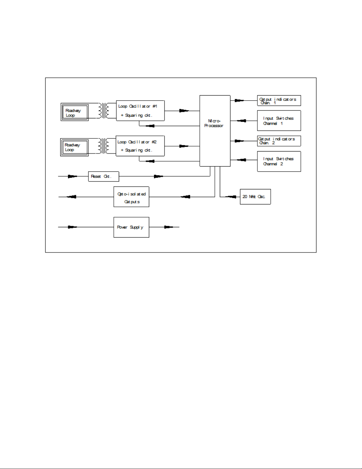
5. Detailed Description of Circuit Operation
The following description is valid for both channels of the DSP-222. Reference
designators are shown for channel 1 with those related to channel 2 in parentheses.
Refer to section 8 for block diagram and schematic.
The loop oscillators consist of two PNP transistors in a basic Franklin type circuit. Q1
(Q4) is coupled to Q2 (Q5) to form the active oscillator. The loop is connected to the
oscillator circuit with the isolation transformer T1 (T2). The reflected roadway loop
inductance is resonated with the capacitor C5 (C11). Frequency modification capacitors
C3 (C9) and C4 (C10) are switched in via SW1 (SW2) and are used to change the
operating frequency of the loop circuit. Neon surge arrestor I1 (I2) provides high voltage
spike protection. When loops are connected to the oscillators and the unit is under
power, the oscillators will resonate at their natural frequency according to the
inductance of the roadway loop and the capacitance described above.
Surge protective diode D1 (D2) is used to limit voltage surges that may appear on the
circuit side of the loop transformer. The output signal from the oscillator is present on
the collector of Q1 (Q4) and is a sine wave at the oscillator frequency.
The loop frequency signals from the oscillators are routed to the squaring circuits
formed by transistor Q3 (Q6). The outputs of the squaring circuits are passed through a
low-pass filter network consisting of resistor R9 (R18) and capacitor C6 (C12). From
here, the square wave loop frequency is presented to the capture register input of the
microprocessor.
The Microchip PIC 16F73 U1 is an advanced RISC microcontroller using Harvard
architecture. The processor is being clocked with a 20 MHz crystal. This speed insures
fast instruction processing as well as a high-speed time base for the two independent
capture registers used in the period measurement of the loop frequencies.

DSP222H_Manual_A Page 5 of 17
The front-panel LED indication LED2 (LED1) is used to indicate the “Call” output of the
channels. LED3 (LED4) indicates the “Fail” condition of the loops. These outputs are
driven directly by the microcontroller. Monolithic voltage regulators provide a stable 12-
volt reference supply U3. Two additional 5-volt regulators provide stable 5-volt power to
the digital circuitry U2 and loop oscillators respectively U4.
An external reset signal is provided to reset the microcontroller with a low (ground true)
signal on pin C of the loop sensor unit. This is accomplished by using Q9 as an input
voltage comparator and phase inverter as well as a second phase inverter Q10. The
input signal is “noise” filtered with C15 and diode D5.
Front-panel switch S1 (S2) is used to input data to the microcontroller from the user.
The sensitivity setting and the choice of pulse or presence operation are routed directly
to the input ports of the microcontroller U1.
Transistor Q7 (Q8) is the high-current driver necessary to power the opto-isolator U5
outputs for external equipment.
The +24 volt input is protected with a power diode D6 to prevent damage to the unit if
power is connected incorrectly. In addition, an input resistor R36 is provided to reduce
inrush current when the unit is plugged into a “hot” card cage. The input voltage is well
filtered with C16.
6. Preventive Maintenance
Over the years, the electronic components used in inductive loop detectors have
become very reliable. Generally, most inductive loop sensor problems can be traced to
the loop system. The loop system is defined as the loop of wire(s) located in the street,
the lead-in wire(s) located between the street loop and the controller cabinet, and the
associated wiring in the controller cabinet itself.
The wire used in the street loop should be rated for direct burial. The wire should be of
the cross-linked polyethylene (XLPE) insulated type. PVC insulated type of wire should
always be avoided. The sealant should be carefully chosen to match the application and
pavement. A hard setting epoxy should never be used with asphalt.
The loop wires should be held into the bottom of the saw cut with backer rod. The loop
wire should be twisted with a minimum of 5 twists per foot between the loop itself and
the splice point. This is usually the hand hole or pull box at the side of the road.
At this point, the twisted loop wires must be soldered to the lead-in cable. If crimp type
connectors are used, they must be soldered after crimping. After soldering, the splices
must be protected with a moisture-proof seal.

DSP222H_Manual_A Page 6 of 17
The feeder cable used to extend the lead-in, must be a shielded, twisted pair with high-
density polyethylene insulation. The termination of the feeder cable in the controller
cabinet must also be soldered if crimp type terminals are used. The use of wire nuts and
other improper methods of connections will result in problems with the detection system.
7. Trouble Analysis
The following chart should be used to troubleshoot the sensor unit and installation. If the
DSP-222 itself is suspect, see section 8 for a complete internal testing sequence.
a) Neither channel responds to vehicles. Power supply fault.
The DSP-222 requires a 24 VDC nominal supply. The sensor unit will operate at
voltages as low as 16 volts. However, supply voltages below this may result in the
sensor unit entering a reset state. In this case, the unit will appear to be non-functional.
b) Reset line held low.
This fault is likely to affect all units in the rack since the external reset line is usually
common to every card rack position. Measure the voltage on the external reset line. If it
is below approximately 12 volts, remove each unit one by one until the reset line returns
to the power supply level (approximately 24 volts). The unit that was removed last
should be checked carefully for other faults. See section 8.
c) Channel does not detect all vehicles.
Sensitivity is too low. Increase sensitivity by one setting and observe operation.
d) Channel is noisy/chatters/gives false detect calls.
Two or more units are interfering with each other (crosstalk). Adjust the frequency
switches on all units that exhibit crosstalk. Continue this procedure until all affected
channels are corrected.
8. Troubleshooting Sequence

DSP222H_Manual_A Page 7 of 17
Apply 24 ±1 volt power to the unit. Connect a loop test box with an inductance of
approximately 115 microhenries to the loop inputs pins D and E (channel 1) and pins J
and K (channel 2) to simulate the connection of loops.
NOTE: All of the following signal measurements are referenced to logic ground.
a) Unregulated power supply.
Voltage across capacitor C16 should be 24 ±1 volt. This voltage can also be measured
at the input of regulator U3 and/or U2.
Possible component faults are diode D6 or resistor R36.
b) Regulated 12 volt power supply.
Voltage at output of U3 (across capacitors C17) should be 12 ± .2 volts. Possible
component fault is the voltage regulator U3.
c) Regulated 5 volt (logic) power supply.
Voltage at output of U2 should be 5 ± .2 volts.
Possible component fault is the voltage regulator U2.
d) Regulated 5 volt (oscillator) power supply.
Voltage at output of U4 should be 5 ± 0.2 volts.
Possible component fault is the voltage regulator U4.
e) Microcontroller clock
Waveform at pin 10 of U1 should be a sine wave at 20 MHz with a peak to peak voltage
of 1 to 2 volts. Note: This value will vary with the type of oscilloscope probe used. The
value stated here is obtained using a Tektronix scope probe with a capacitance of 20
pF.

DSP222H_Manual_A Page 8 of 17
Possible components at fault are the crystal X1 or microcontroller U1.
f) Reset input to microcontroller
Voltage at pin 1 of U1 should be 5 volts ± .2 volts. Check to insure pin C on the detector
is high--approximately 24 volts.
Possible components at fault are transistors Q9, Q10, or diode D5.
g) Loop oscillator output
Connect an oscilloscope to pin 13 (pin 12) of U1. Observe the square wave to be the
same frequency as the loop oscillator. At this point, a simulated call should be
introduced at the test box. Observe a slight frequency increase at this point.
If there is no square wave at this point a defective component in the oscillator circuit
may exist. Possible components at fault are Q1 (Q4), Q2 (Q5), Q3 (Q6), D3 (D4) or the
potcore isolation transformer T1 (T2).
h) Outputs and indicators
Verify that the opto-isolated outputs conducts only when the front-panel detect LEDs are
on.
Possible fault areas are: Transistor Q7 (Q8) or the dual opto-isolator U2 or LED2
(LED1)

DSP222H_Manual_A Page 9 of 17
9. Bill of Materials
Qty
Reference
Description
Manufacturing Part Number
2
C13, 14
22 pF 50V NPO SMD 805
Panasonic/ECU-V1H22OJCN
2
C6, 12
270 pF 50V X7R SMD 805
Kemet/C805C271M5RAC
2
C2, 8
.001uF 50V NPO SMD 805
Panasonic/ECU-V1H102JCX
10
C1,7,15,17-20,22-24
1uF 50V X7R SMD 1206
Kemet/C1206C104M5RAC
2
C3, 9
.022uF 50V PPS 1910
Panasonic/ECH-U1H223JB5
2
C4, 10
.047uF 50V PPS 1812
Panasonic/ECH-U1H473JB9
2
C5, 11
.1uF 50V PPS 1913
Panasonic/ECH-U1H104JB9
2
C25,26
.47uf X7R SMD 1206
AVX 12063C474KAT2A
2
C16, 21
220uF 35V elect SMD
Elna/RV-35V221MH10-R
1
—
–
DSP-222 alum. front panel
Diablo P/N CAS013
1
—
–
Oscillator plastic cover
Modar/JIT minibox
2
J1, 2
2 pins .025” sq. x .1” center
generic
7
D3-5, 7-10
1N914 SMD SOT-23
Motorola MMBD914LT1
1
D6
1N4004 1 amp 400V SMD SMA
Diodes, Inc S1G-13
2
Z1, 2
33V zener SMD SOD-123
Diodes, Inc MMSZ5257B
2
D1, 2
11V transorb SMD SMB
Diodes, Inc SMBJ11CA
2
LED3, 4
Right angle green LED
Bivar/H101CSGC
2
LED1, 2
Right angle red LED
Bivar/H101CSRC
2
I1,2
NE-2E neon indicator
Xenell
2
—
–
#4-3/8” Phil self-tap screw
generic
2
—
–
#4-40 5/16” screw w/ washer
generic
2
—
–
Right angle bracket
Diablo P/N HDW025
1
—
–
Handle
Diablo P/N HDW030
2
—
–
#6-3/8” Phil self-tapping screw
generic
2
U2, 4
+5V regulator SMD D2PAK
On Semi M7805CD2T
1
U3
+12V regulator SMD D2PAK
On Semi M7812CD2T
1
U5
Dual opto-coupler SMD SO-8
Fairchild MOCD223
1
U1
PIC microcontroller
Microchip PIC16F73-20/SO
1
—
–
2-channel oscillator box label
Diablo LBL032
1
—
–
Front panel label
Diablo LBL037
1
—
–
DSP-222 main PCB
Diablo PCB222
2
R1, 10
68 ohm 1/8 watt SMD 1206
generic
1
R36
10 ohm 1/2 watt SMD 1206
generic
6
R9, 18, 24, 25, 39, 40
330 ohm 1/8 watt SMD 1206
generic
2
R2, 11
510 ohm 1/2 watt SMD 1206
generic
6
R20-23, 37, 38
1K 1/8 watt SMD 1206
generic
16
R3, 5, 7, 8, 12, 14, 16, 17, 26-29, 31,
32, 34, 35
4.7K 1/8 watt SMD 1206
generic
4
R19, 30, 33, 41
12K 1/8 watt SMD 1206
generic

DSP222H_Manual_A Page 10 of 17
2
R4, 13
27K 1/8 watt SMD 1206
generic
2
R6, 15
56K 1/8 watt SMD 1206
generic
7
Q3, 6-8, 10-12
2N3904 NPN SMD SOT-23 transistor
Motorola MMBT3904LT1
5
Q1, 2, 4, 5, 9
2N3906 SMD SOT-23 transistor
Motorola MMBT3906LT1
2
S1, 2
6 position right angle DIP switch
Switronic DA06BTS
2
T1, 2
Potcore isolation transformer
Diablo P/N XFM060
1
X1
20 Mhz Xtal-parallel 20 pF HC-49UA
Fox 200-20-1
DSP222H_Manual_A Page 11 of 17
10. Block Diagram
11. Schematic (next page)

DSP222H_Manual_A Page 12 of 17
This page left intentionally blank.
Remove and insert B-size schematic.

DSP222H_Manual_A Page 13 of 17
12.Assembly Drawing
13. Specifications
Power Supply:
24 VDC ±20%, 80 ma maximum for both channels.
Loop Input:
The loop inputs incorporate lightning and transient protection devices and the loop
oscillator circuitry is transformer isolated. The lightning protection will withstand the
discharge of a 10 microfarad capacitor charged to 2,000V across the loop inputs or
between any loop input and earth ground.

DSP222H_Manual_A Page 14 of 17
Tuning:
Each channel of the DSP-222 series will automatically tune to any loop and lead-in
combination within the tuning range upon application of power or when a valid reset
signal is received. A channel can be reset by adjusting mode, sensitivity, or frequency.
Tuning Range:
50 to 750 µH with a “Q” greater than 5.
Lead-in Length:
The unit will operate with lead-in (feeder) lengths up to 2,000 feet with Caltrans types A,
B, or Q loops in all configurations as defined by California Standard Plan ES-5A & B.
Environmental Tracking:
The DSP-222 automatically and continuously compensates for environmental changes
and effects throughout the entire tuning range and operating temperature range.
Fault Monitoring:
Internal monitoring of the loop system is accomplished with the microcontroller. The
system is able to detect shorted or open loop systems, as well as a sudden change of
inductance exceeding 25 % of the nominal value. If a fault is detected on a channel, the
Fail LED will flash in a sequence related to the type of fault. The channel output will
remain in the detect (call) state. If the fault condition is removed, the detect LED and the
output will return to normal operation.
High-Intensity LED Indicators:
Each channel has a high-intensity red LED indicator to indicate the presence, or “call”
and a high-intensity green LED indicator to indicate a failure in the roadway loop
system.

DSP222H_Manual_A Page 15 of 17
Front Panel Controls:
Front panel mounted DIP switches allow the user to select sensitivity, pulse/presence
and frequency on each channel.
Operational Modes:
Pulse - 125 ms ±25 ms momentary output
Presence Time - Meets or exceeds the State of California (Caltrans) Specifications.
(Minimum presence = 10 minutes for a change of inductance of 0.06% and minimum
presence = 3 minutes for a change of inductance of 0.02%)
Note: When operating in the pulse mode, a vehicle remaining over a loop will inhibit
further pulse outputs from being issued for a period of 2 seconds after which time
vehicles passing over the loop will again be detected.
Sensitivity:
One of seven settings may be selected to optimize detection on varying loop and lead-in
configurations. Sensitivity is defined as the minimum percentage change in ∆L/L of the
total inductance (loop plus lead-in). Selecting level 0 will switch the channel off. In this
condition, the loop oscillator is de-energized, and the output will remain in the no call
state.
Sensitivity
∆
L%
Response Time (ms)
0Off Off
1.64 .5
2.32 1
3.16 2
4.08 4
5,04 8
6.02 16
7.01 32

DSP222H_Manual_A Page 16 of 17
Frequency:
One of four settings may be selected to eliminate crosstalk.
Reset Input:
The DSP-222 may be reset by applying a ground true logic level to the reset input pin C
for a period exceeding 15 microseconds.
Electrical Interconnection:
Edge Connector mates with connector types. Cinch 50-44A-30
Pins Function
A Power and logic common
B Input power (+24 volts DC)
C /Reset
D Loop 1
E Loop 1
F Output 1 (collector)
H Output 1 (emitter)
J Loop 2
K Loop 2
L Chassis ground
M N/C
N N/C

DSP222H_Manual_A Page 17 of 17
Output Ratings:
Optically Isolated Output Versions: the output transistor is rated for a maximum collector
voltage of 30 VDC. Maximum collector current is 50 mA.
Mechanical:
Dimensions 1.12 W x 4.5H x 7.0 (Excluding handle)
Environmental:
Temperature Range:
Storage: -55C to +85C
Operating: -37°C to +74°C
Humidity: 0 to 95% relative
Table of contents


