Henkel Loctite EQ ACCE D Series Technical Document
EQ ACCE Robot D-Series Junc Box 24V
IDH #: 2182205
Equipment Instructions


EQ ACCE Robot D-Series Junc Box 24V IDH #: 2182205
Equipment Instructions
1
Table of Contents
1Please Observe the Following .............................................................................................. 3
1.1.Emphasized Sections ..................................................................................................... 3
1.2.For Your Safety .............................................................................................................. 3
1.3.Unpacking and Inspection .............................................................................................. 4
1.4.Items supplied ................................................................................................................ 4
2Description ............................................................................................................................ 4
3Technical Data ...................................................................................................................... 4
4Installation ............................................................................................................................. 4
5Operation .............................................................................................................................. 5
5.1.D-Series Junction Box Internal Layout ........................................................................... 5
5.2.Installation of Cord Grips or Strain Reliefs ..................................................................... 6
5.3.Junction Box D-Sub Connections ................................................................................... 6
5.4.Input Circuits ................................................................................................................... 7
Example 1: Sourcing Input (Negative Logic) with Dry Contact Switch .................................. 7
Example 2: Sinking Input (Positive Logic) with Dry Contact Switch ...................................... 8
Example 3: Proximity Sensor Input – Sourcing (Negative Logic) / Sinking (Positive Logic) 10
5.5.Output Circuits .............................................................................................................. 1 2
Example 4: Sourcing Output (Positive Logic, PNP) ............................................................ 12
Example 5: Sinking Output (Negative Logic, NPN). ............................................................ 14
5.6.Installation of Needle Calibration Kit (1569523) ........................................................... 16
7Troubleshooting .................................................................................................................. 16
9Accessories and Related Components ............................................................................... 16

EQ ACCE Robot D-Series Junc Box 24V IDH #: 2182205
Equipment Instructions
2
10Connector Pin Assignments ................................................................................................ 17
10.1.ROBOT SUB-D CONNECTOR ................................................................................. 17
10.2.XS1 OUT SUB-D CONNECTOR .............................................................................. 17
10.3.XS2 IN SUB-D CONNECTOR .................................................................................. 17
10.4.SOL VLV SUB-D CONNECTOR ............................................................................... 18
10.5.RBT DISP SUB-D CONNECTOR ............................................................................. 18
11Warranty .............................................................................................................................. 1 9

EQ ACCE Robot D-Series Junc Box 24V IDH #: 2182205
Equipment Instructions
3
1 Please Observe the Following
1.1. Emphasized Sections
Warning!
Refers to safety regulations and requires safety measures that protect the operator or
other persons from injury or danger to life.
Caution!
Emphasizes what must be done or avoided so that the unit or other property is not
damaged.
Notice:
A notice gives recommendations for better handling of the unit during operation or
adjustment as well as for service activities.
1.2. For Your Safety
For safe and successful operation of the unit, read these instructions completely.
If the instructions are not observed, the manufacturer can assume no
responsibility.
Do not expose the connecting cable to heat, oil, or sharp edges.
Make sure the Unit stands stable and secure.
Use only original equipment replacement parts.
Do not operate the Unit outside its design. Damage to the unit and robot can
occur.
Always disconnect the power supply before servicing the unit.
Observe general safety regulations for the handling of chemicals such as
Loctite® adhesives and sealants. Observe the manufacturer’s instructions as
stated in the Safety Data Sheet.
While under warranty, the unit may be repaired only by an authorized Loctite
service representative.

EQ ACCE Robot D-Series Junc Box 24V IDH #: 2182205
Equipment Instructions
4
1.3. Unpacking and Inspection
Carefully unpack the Loctite® EQ ACCE D-Series Junc Box 24V and examine the
items contained in the carton. Inspect the unit for any damage that might have
occurred in transit. If such damage has occurred, notify the carrier immediately.
Claims for damage must be made by the consignee to the carrier and should be
reported to the manufacturer.
1.4. Items supplied
(1) EQ ACCE D-Series Junc Box 24V
(1) D-Sub 25 pin cable – male to female
(1) D-Sub 9 pin cable – male to female
(1) Equipment Instructions for EQ ACCE D-Series Junc box 24V
2 Description
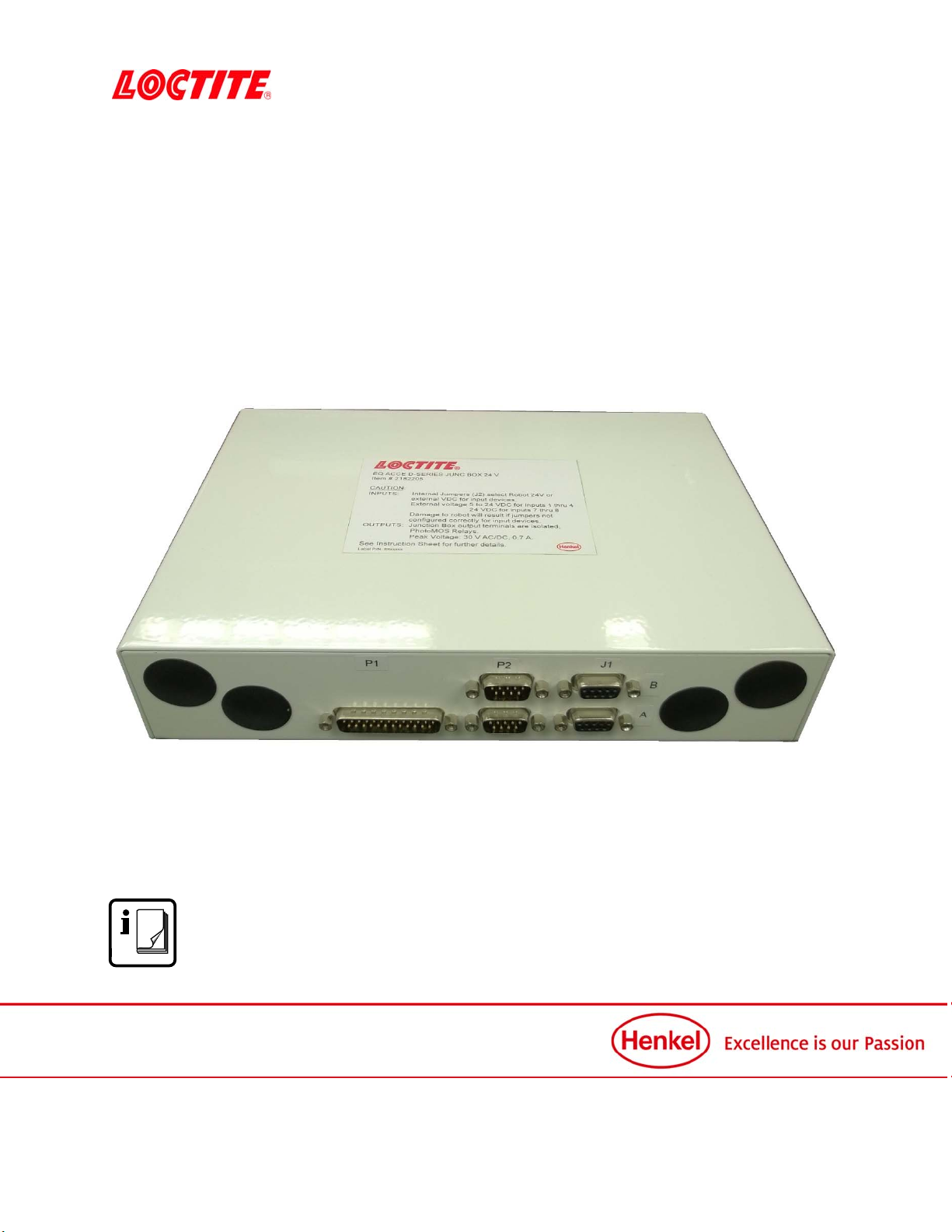
EQ ACCE D-Series Junc Box 24 V, part number 2182205 provides isolated input and
output connections between Loctite 24 Volt D-series robots and external devices such as
solenoids and sensors.
The EQ ACCE D-Series Junc Box 24V is only compatible with the Loctite 24-volt
D-Series and Loctite 24-volt RB15, RB20, & RB40 D-Series robots.
Do not connect EQ ACCE D-Series Junc Box 24V to any other Loctite Robots.
3 Technical Data
Dimensions (L x H x W): 7” x 2” x 10” [177.8 mm x 50.8 mm x 254 mm]
Total weight: 4 lbs. (1.8 Kg)
Operating Voltage:
Input 1….4: 5 … 24 VDC
Input 5.…8: 24 VDC
Output 1….8: 24 V DC/AC-peak
Output Type: solid state relay, maximum(peak) current 2.5 Amperes;
1 through 4 normally open;
5 through 8 normally open & normally closed.
4 Installation
Before using the equipment for the first time check it carefully for signs of external
damage. If any shipping damage is found DO NOT USE THE EQUIPMENT – return it
to your supplier immediately.
EQ ACCE Robot D-Series Junc Box 24V IDH #: 2182205
Equipment Instructions
5
5 Operation
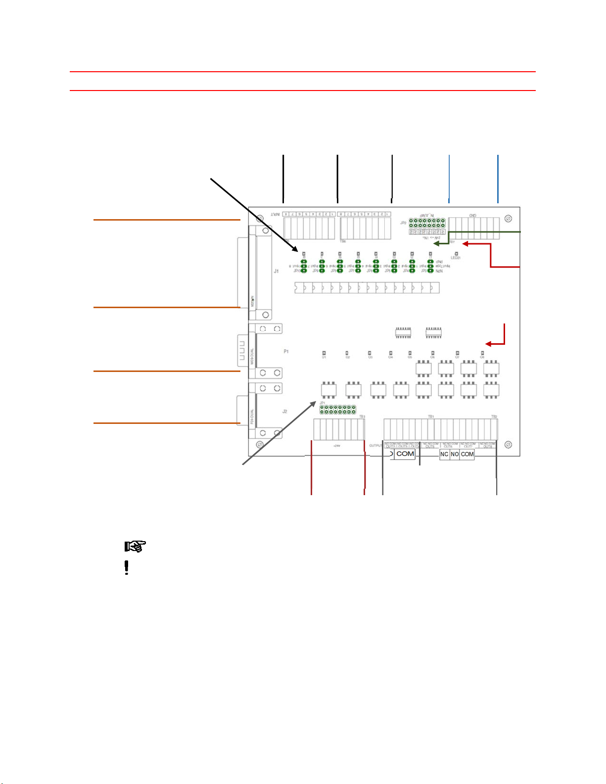
5.1. D-Series Junction Box Internal Layout
Input numbers 1 through 4 accept Vcc range +5 to +24 VDC.
When using external Vcc for any inputs, remove Jumpers from JP2 for that input
to avoid damaging the Junction box.
25-Pin I/O connector to Robot
Ground
from
Robot
Dual D-Sub 9 pin male connector
Upper for SX1 OUT for Loctite
Controllers (Output #1)
Lower for Robot Valve Solenoid
Assembly 988000
Dual D-Sub 9 pin female connector
Upper for XS2 IN (Input #7)
Lower for D-Series Robot Dispense Cable
Output LEDs -
RED
Input LEDs -
Green
Power LED -
Red
Jumpers pass
+24 V from
Robot to Input
Connector
+24 V from
Robot when
jumped.
(Input Vcc)
To Robot
Opto Input.
Jumpers Pass +24 Volts from
Robot to COM of Respective
SSR Output Solid State Relay Output
Connections
NOTE: # 1-4 SPST-NO, # 5-8 SPDT
Output 1 is accessible through D-Sub
9 pin connector on side of board.)
+24 Volts
Direct from
Robot
Input Type Jumpers
Set for NPN (Sink) or
PNP (Source).

EQ ACCE Robot D-Series Junc Box 24V IDH #: 2182205
Equipment Instructions
6
5.2. Installation of Cord Grips or Strain Reliefs
Four capped locations are provided on the enclosure for customer supplied cord
grips.
Hole Diameter: 0.813” [20.7mm]
Number Holes: 4
5.3. Junction Box D-Sub Connections
There are 5 D-sub connectors on the Junction box for 24 Volt D-series robots.
D-SUB
Connector
pins & Type
Label on D-Series
Junction Box Connection Description
DB25-Male ROBOT I/O PORT TO 24 Volt D-Series Robot I/O Port connector
DB9-Male SOL VLV Dedicated connection for Solenoid Valve Module 24
VDC for D-Series Robot Material/IDH # 591031.
DB9-Male XS1 OUT TO Loctite Controller XS1 start input
(Robot Output #1)
DB9-Female RBT DISP Dedicated connection for D-Series
Dispenser Cable included with Robot
DB9-Female XS2 IN Robot Input # 7 typically used for
Loctite reservoir low level sensor.
ROBOT I/O PORT connection using a DB25 through cable to robot.
SOL VLV and RBT DISP dedicated for Solenoid Valve Module 24 VDC for D-Series Robot
(purchased separately) and D-Series Dispenser Cable (included with Robot).
Do not connect any other devices to these ports. Will cause damage.
XS1 OUT is robot OUTPUT#1 typically used as start signal to Loctite UV flood or CureJet
controllers. Can be used to control an external solenoid valve or relay.
there is no internal terminal block connection for robot OUTPUT #1.
XS2 IN is robot Input #7 typically used for Loctite product reservoir low level signal. Can also be
used with external switch or proximity sensor.
Do not use the internal terminal block connection for robot Input #7 when using this
D-sub connection. Will cause damage to the junction box and robot.
0.813” Diameter Holes
with covers
EQ ACCE Robot D-Series Junc Box 24V IDH #: 2182205
Equipment Instructions
7
5.4. Input Circuits
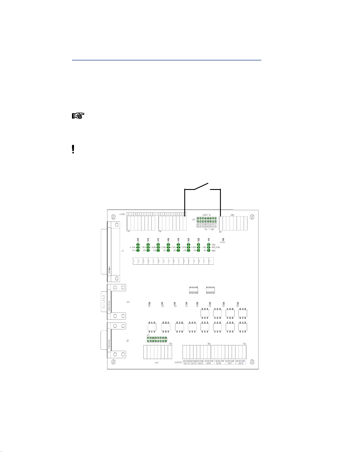
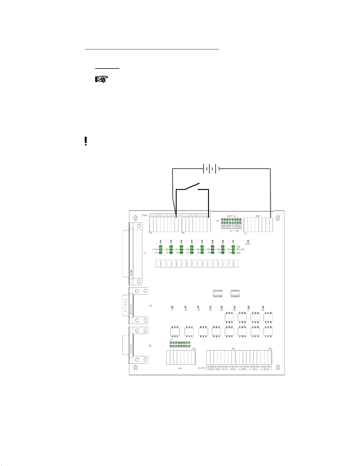
Example 1: Sourcing Input (Negative Logic) with Dry Contact Switch
Input #x type Jumper installed for NPN.
Jumper JP2-INx installed for Robot +24 VDC.
Connect one side of the external switch to TB6-x
Connect other side of the external switch to ground (TB7 “GND”).
Where x equals the input number (1 through 8).
Best to use robot internal 24 VDC for a dry contact switch. If an external
voltage source is needed, Remove the JP2-INx Jumper. Connect power
supply +24 VDC (+5…+24 VDC for inputs 1 through 4) to TB5-x. Connect
power supply 0 VDC to TB7-GND.
Do not use connect an external power supply on an input with jumper JP2-
INx installed.
Ground connection
(Use any position)
25-Pin I/O
connector to
Robot
External Switch
Connection to Robot Input # 1
EQ ACCE Robot D-Series Junc Box 24V IDH #: 2182205
Equipment Instructions
8
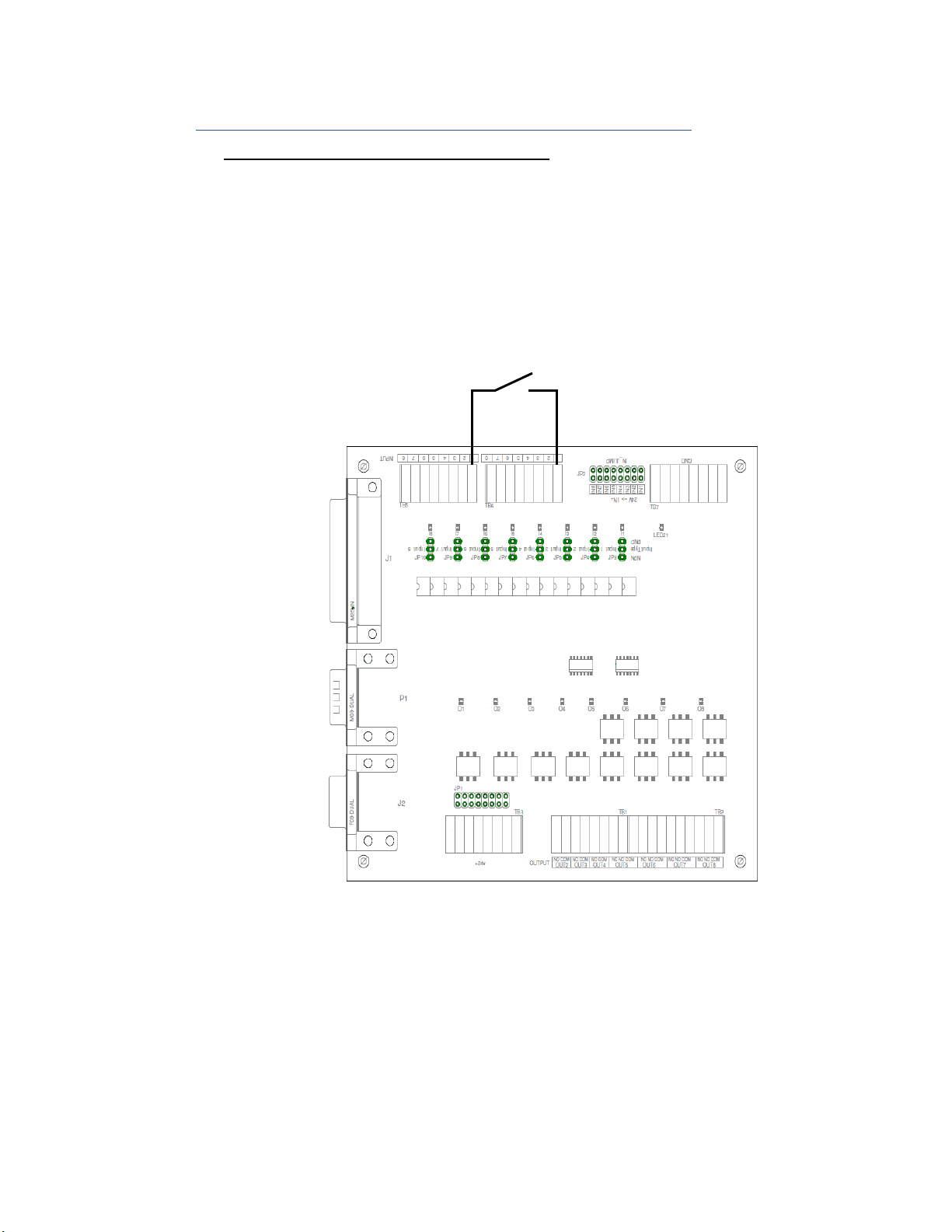
Example 2: Sinking Input (Positive Logic) with Dry Contact Switch
USING ROBOT 24 VDC POWER SUPPLY
Input #x type Jumper installed for PNP.
Jumper JP2-INx installed for Robot +24 VDC.
Connect one side of the external switch to TB6-x
Connect other side of the external switch to TB5- x
Where x equals the input number (1 through 8).
JP2-IN1 Jumper
in place for Robot 24V
25-Pin I/O
connector to
Robot
External Switch
Connection to Robot Input # 1
EQ ACCE Robot D-Series Junc Box 24V IDH #: 2182205
Equipment Instructions
9
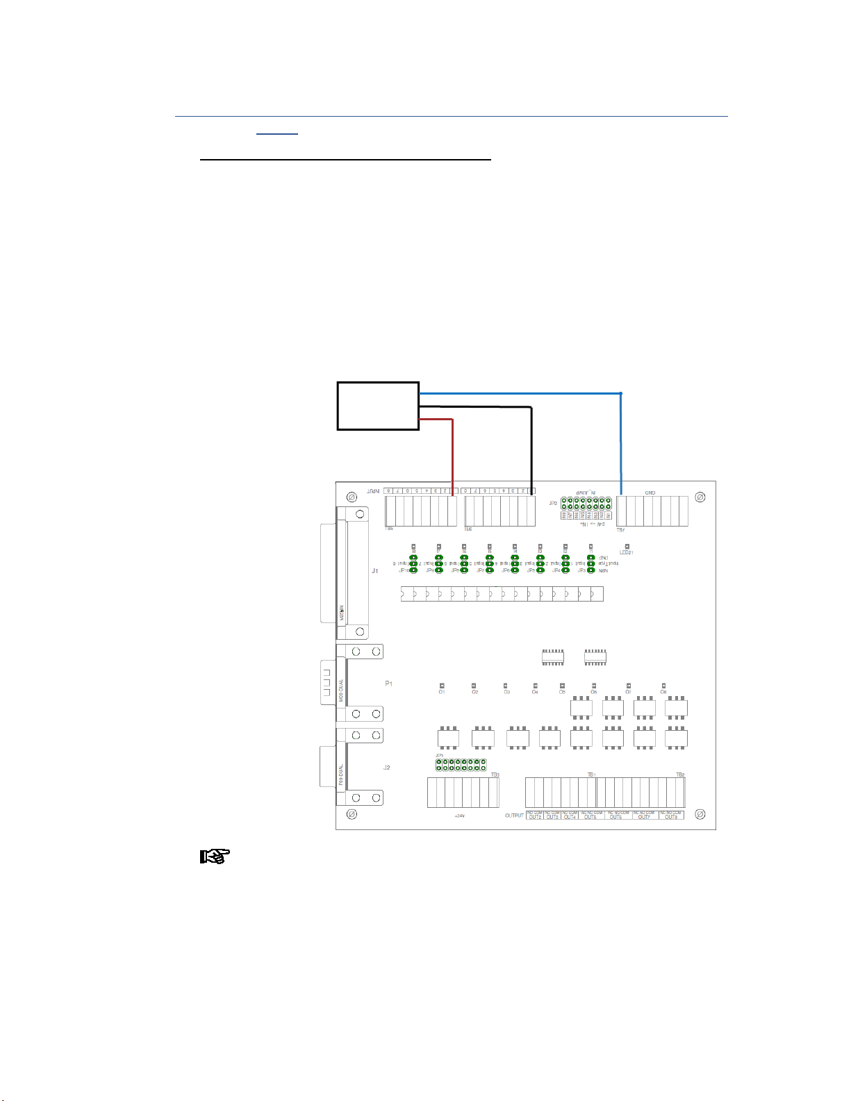
USING EXTERNAL 24 VDC POWER SUPPLY
Input #x type Jumper installed for PNP.
Remove Jumper JP2-INx for External +24 VDC.
Inputs 1 through 4 accept 5…24 VDC. Inputs 5 through 8 are 24 VDC.
Connect one side of the external switch to TB6-x
Connect other side of the external switch to TB5- x
Connect power supply 0 VDC to Ground (TB7 “GND”)
Connect power supply +24 VDC TB5-x
Where x equals the input number (1 through 8).
Do not use connect an external power supply on an input with jumper
JP2-INx installed.
Remove JP2-IN1
Jumper for external 24V
25-Pin I/O
connector to
Robot
External Switch
Connection to Robot Input # 1
External 24 VDC
EQ ACCE Robot D-Series Junc Box 24V IDH #: 2182205
Equipment Instructions
10
Example 3: Proximity Sensor Input – Sourcing (Negative Logic) / Sinking (Positive
Logic)
USING ROBOT 24 VDC POWER SUPPLY
Input #x type Jumper installed for PNP or NPN based on proximity sensor
type.
Jumper JP2-INx installed for Robot +24 VDC.
Place a Jumper across JP2 pins at “IN1” – Input 1 Internal Robot Voltage
Proximity Sensor (3-wire):
o Connect brown wire (+V) to TB5-x.
o Connect blue wire (0V) to TB7 “GND.
o Connect black wire (signal) to TB6-x.
Where x equals the input number (1 through 8).
If the robot input does not register the state change and junction box input
LED is registering the state change of the proximity sensor; Change jumper
for input type to the other position.
25-Pin I/O connector to Robot
Ground connection
(Use any position)
Proximit
y
Switch
Connection
to Robot
Input # 1
Connect +V to TB5-1 with
j
umper on JP2-“IN1” pins
for robot 24 VDC.
+24 Volts from Robot

EQ ACCE Robot D-Series Junc Box 24V IDH #: 2182205
Equipment Instructions
11
USING EXTERNAL 24 VDC POWER SUPPLY
Input #x type Jumper installed for PNP or NPN based on proximity sensor
type.
Remove Jumper JP2-INx for External +24 VDC.
Inputs 1 through 4 accept 5…24 VDC. Inputs 5 through 8 are 24 VDC.
Proximity Sensor (3-wire):
o Connect brown wire (+V) to TB5-x.
o Connect blue wire (0V) to TB7 “GND.
o Connect black wire (signal) to TB6-x.
Connect power supply 0 VDC to Ground (TB7 “GND”)
Connect power supply +24 VDC TB5-x
Where x equals the input number (1 through 8).
Do not use connect an external power supply on an input with jumper
JP2-INx installed.
If the robot input does not register the state change and junction box input
LED is registering the state change of the proximity sensor; Change jumper
for input type to the other position.
25-Pin I/O connector to Robot
Ground connection
(Use any position)
Proximit
y
Switch
Connection
to Robot
Input # 1
Connect +V to
TB5-1 with NO
j
umper on
JP2-“IN1” pins
for external
DC voltage.
Volts DC from
External Supply
EQ ACCE Robot D-Series Junc Box 24V IDH #: 2182205
Equipment Instructions
12
5.5. Output Circuits
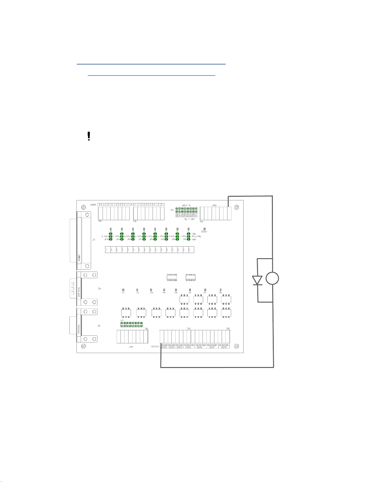
Example 4: Sourcing Output (Positive Logic, PNP)
USING ROBOT 24 VDC POWER SUPPLY
Jumper JP1-x installed - robot +24 Volts at output x common terminal.
Connect solenoid control valve coil (+) to OUTx
Connect solenoid control valve coil (-) to ground (TB7 “GND”).
Where x equals the input number (1 through 8).
Suppression Diode is required for all coils or Inductive loads. Make sure that
these devices suppression diode. If the device does not have suppression diode,
an external suppression diode needs to be added.
Turn Robot Output 2 on
to energize solenoid.
Solid State Rela
y
Connections
Ground connection
(Use any position)
25-Pin I/O
connector
to Robot
+24 V
o
l
ts
fr
o
m R
obot
24 Volt DC Solenoid
Do Not Exceed Robot
Output Current Limit of
250 mA (total Current,
taking inrush into
account)
Diode
(
mandator
y)

EQ ACCE Robot D-Series Junc Box 24V IDH #: 2182205
Equipment Instructions
13
USING EXTERNAL 24 VDC POWER SUPPLY
Remove Jumper JP1-x – External power at output x common terminal.
Do not use connect an external power supply with jumper JP1-x
installed.
Connect solenoid control valve coil (+) to external power supply +V.
Connect solenoid control valve coil (-) to OUTx-NO
Connect external power supply 0V to OUTx-COM
Where x equals the input number (1 through 8).
Suppression Diode is required for all coils or Inductive loads. Make sure that
these devices suppression diode. If the device does not have suppression diode,
an external suppression diode needs to be added.
Turn Robot Output 2 on
to energize solenoid.
Solid State Rela
y
Connections
25-Pin I/O
connector
to Robot
24 Volt DC Solenoid
Do Not Exceed Output Current Limit of
External Supply or Solid State Relay Rating.
Diode
(
mandator
y)
24 Volt DC External Power Supply

EQ ACCE Robot D-Series Junc Box 24V IDH #: 2182205
Equipment Instructions
14
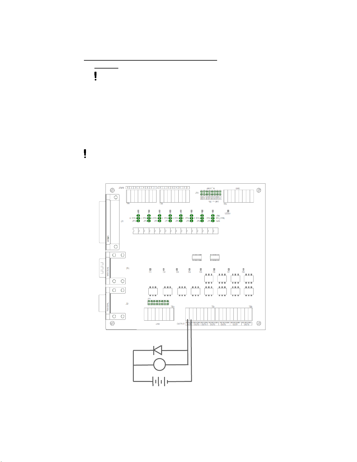
Example 5: Sinking Output (Negative Logic, NPN).
USING ROBOT 24 VDC POWER SUPPLY
Remove JP1-x installed - robot +24 Volts at output x common terminal.
Connect OUTx-COM to ground (TB7 “GND”).
Do not use connect an external power supply or connect to Ground
with jumper JP1-x installed.
Connect solenoid control valve coil (+) to TB3 robot +24VDC
Connect solenoid control valve coil (-) to OUTx-NO.
Suppression Diode is required for all coils or Inductive loads. Make sure that
these devices suppression diode. If the device does not have suppression diode,
an external suppression diode needs to be added.
Turn Robot Output 2 on
to energize solenoid.
Solid State Rela
y
Connections
Ground connection
(Use any position)
25-Pin I/O
connector
to Robot
+24 Volts from Robot
Diode
(
mandator
y)
24 Volt DC Solenoid
Do Not Exceed Robot
Output Current Limit of
250 mA (total Current,
taking inrush into
account)
EQ ACCE Robot D-Series Junc Box 24V IDH #: 2182205
Equipment Instructions
15
USING EXTERNAL 24 VDC POWER SUPPLY
Remove Jumper JP1-x – External power at output x common terminal.
Do not use connect an external power supply with jumper JP1-x
installed.
Connect solenoid control valve coil (+) to external power supply +V.
Connect solenoid control valve coil (-) to OUTx-NO
Connect external power supply 0V to OUTx-COM
Where x equals the input number (1 through 8).
Suppression Diode is required for all coils or Inductive loads. Make sure that
these devices suppression diode. If the device does not have suppression diode,
an external suppression diode needs to be added.
Turn Robot Output 2 on
to energize solenoid.
Solid State Rela
y
Connections
25-Pin I/O
connector
to Robot
24 Volt DC Solenoid
Do Not Exceed Output Current Limit of
External Supply or Solid State Relay Rating.
Diode
(
mandator
y)
24 Volt DC External Power Supply

EQ ACCE Robot D-Series Junc Box 24V IDH #: 2182205
Equipment Instructions
16
5.6. Installation of Needle Calibration Kit (1569523)
When adding the Needle Calibration Kit to a D-Series Robot with the
EQ ACCE D-Series Junc Box 24V, the Needle Calibration Kit needs to
be wired through the junction box.
Steps for wiring the Needle Calibration Kit to the EQ ACCE D-Series Junc Box 24V:
Remove the 25-Pin D-Sub Plug from the cable assembly.
The outer cable jacket is stripped back to expose 7” [178 mm] of the internal
wires.
Label wires based on D-Sub pin position (see 1
st
table below).
Add strain relief to junction box with appropriate sized cord grip.
Connect wires to the appropriate Junction Box Terminal Blocks (1
st
table)
Set Junction Box Jumpers as indicated on second table below.
25 Pin Connector Wire Junction Box – Terminal Block
Pin # Description Color Designation Description
25 24 VDC Red TB3 +24 VDC
1 X Signal Yellow TB6-1 IN1
13 GND Black TB7 GND
2 Y/Z Signal White TB6-2 IN2
Junction Box Jumper Settings for Needle Calibration
Designation Setting Description
JP2-IN1 Installed Internal +24 VDC
JP2-IN2 Installed Internal +24 VDC
JP3 NPN Sourcing Input (Negative Logic)
JP4 NPN Sourcing Input (Negative Logic)
7 Troubleshooting
Before proceeding with any repair or maintenance operation turn off and disconnect the
main electricity supply to the system.
9 Accessories and Related Components
Loctite Part No. Description
89XXXX Cable, Male to Female, D-Sub 25 pin
989432 Cable, Male to Female, D-Sub 9 pin
591031 Solenoid Valve Module 24 VDC for D-Series Robot
1569523 Needle Calibration Kit
25-Pin
D-Sub
EQ ACCE Robot D-Series Junc Box 24V IDH #: 2182205
Equipment Instructions
17
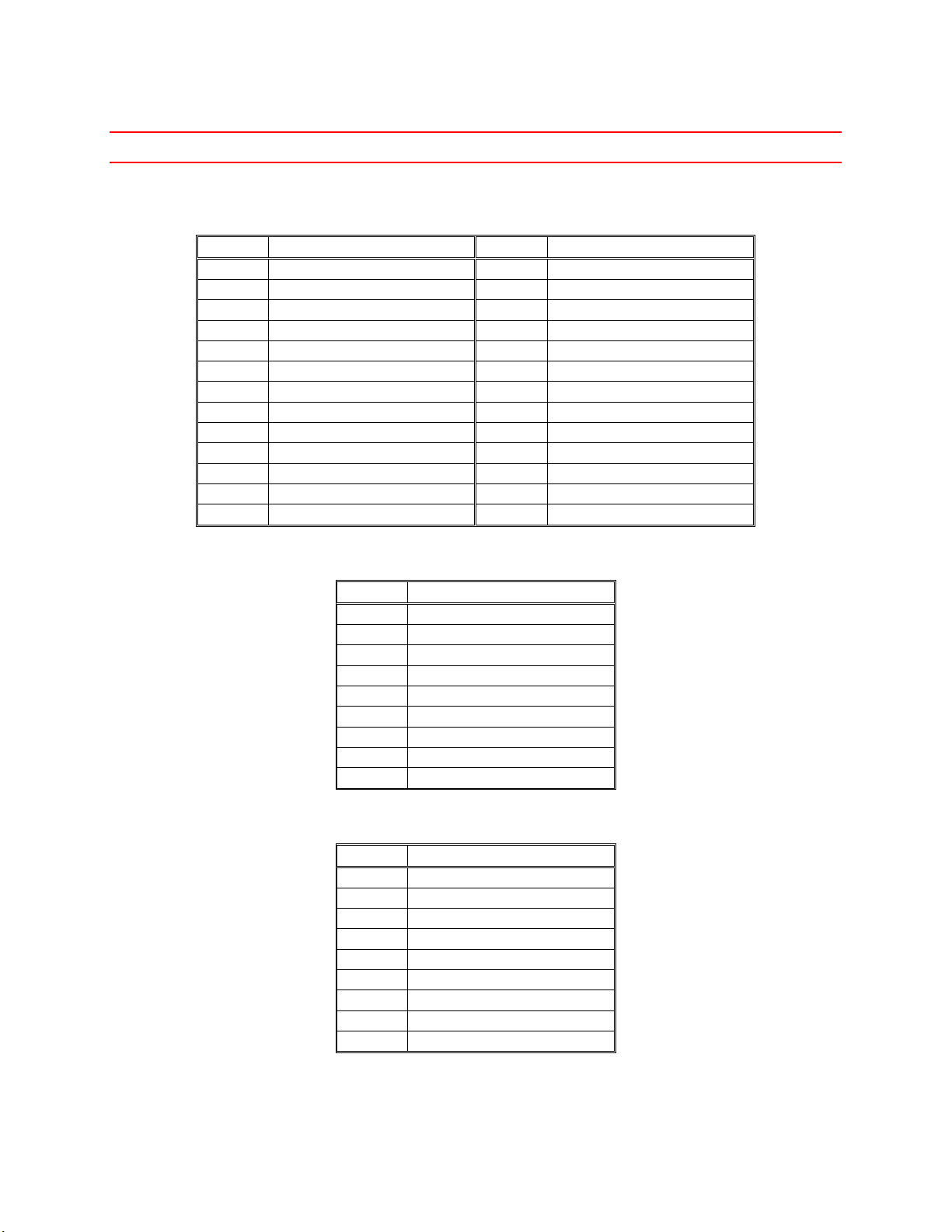
10 Connector Pin Assignments
10.1. ROBOT SUB-D CONNECTOR
Pin # Description Pin # Description
1 IN # 1 (X Signal) 14 OUTPUT # 1 (Disp Start)
2 IN # 2 (Y/Z Signal) 15 OUTPUT # 2
3 IN # 3 16 OUTPUT # 3
4 IN # 4 (Disp Ready) 17 OUTPUT # 4
5 IN # 5 18 OUTPUT # 5
6 IN # 6 19 OUTPUT # 6
7 IN # 7 (Low Level) 20 OUTPUT # 7
8 IN # 8 21 OUTPUT # 8
9 NC 22 NC
10 NC 23 NC
11 COM GND 24 +24V
12 COM GND 25 +24V
13 COM GND
10.2. XS1 OUT SUB-D CONNECTOR
Pin # Description
1 OUT1-NO
2 No Connection
3 No Connection
4 No Connection
5 Jumper to Pin # 8
6 No Connection
7 No Connection
8 Jumper to Pin # 5
9 OUT1-COM
10.3. XS2 IN SUB-D CONNECTOR
Pin # Description
1 IN7
2 No Connection
3 No Connection
4 No Connection
5 Robot 0 VDC
6 No Connection
7 No Connection
8 No Connection
9 Robot +24 VDC
EQ ACCE Robot D-Series Junc Box 24V IDH #: 2182205
Equipment Instructions
18
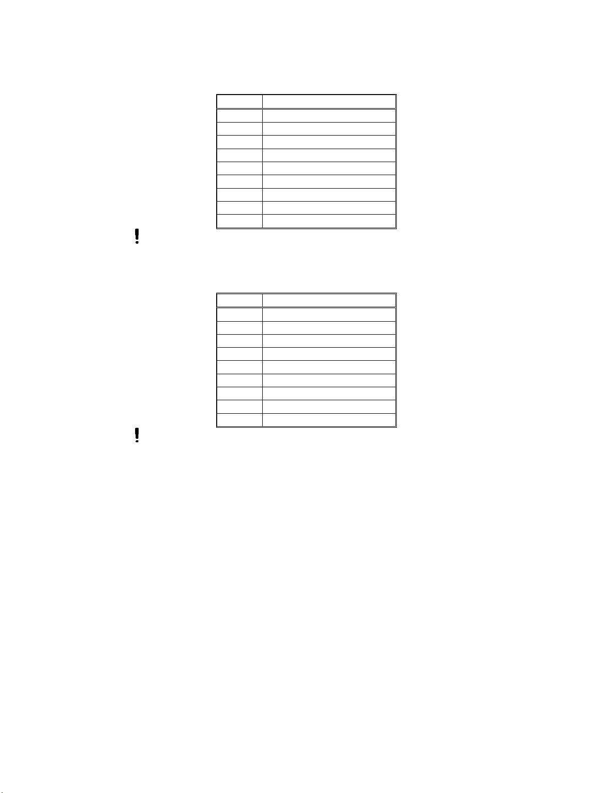
10.4. SOL VLV SUB-D CONNECTOR
Pin # Description
1 No Connection
2 No Connection
3 Robot 0 VDC
4 No Connection
5 No Connection
6 Robot 0 VDC
7 No Connection
8 No Connection
9 to RBT DISP Pin # 1
Do not use this connector with any other devices. This connection is only reserved
for the Solenoid Valve Module 24 VDC for D-Series Robot, Material/IDH # 591031.
10.5. RBT DISP SUB-D CONNECTOR
Pin # Description
1 to SOL VLV Pin # 1
2 No Connection
3 No Connection
4 No Connection
5 No Connection
6 No Connection
7 No Connection
8 No Connection
9 Robot +24 VDC
Do not use this connector with any other devices. This connection is only reserved for the
for D-Series Dispenser Cable (included with Robot).
This manual suits for next models
1
Table of contents
Other Henkel Industrial Equipment manuals


Popular Industrial Equipment manuals by other brands


PCB Piezotronics
PCB Piezotronics TORKDISC 5309D-01A Installation and operating manual

LNS
LNS QL Servo 80 S2 Service manual

HOLZMANN MASCHINEN
HOLZMANN MASCHINEN SKM 470S user manual

Alfalaval
Alfalaval IsoMix External Drive instruction manual

GSI Group
GSI Group SCR Series instruction manual

GAPOSA
GAPOSA P200 Series Reference manual


