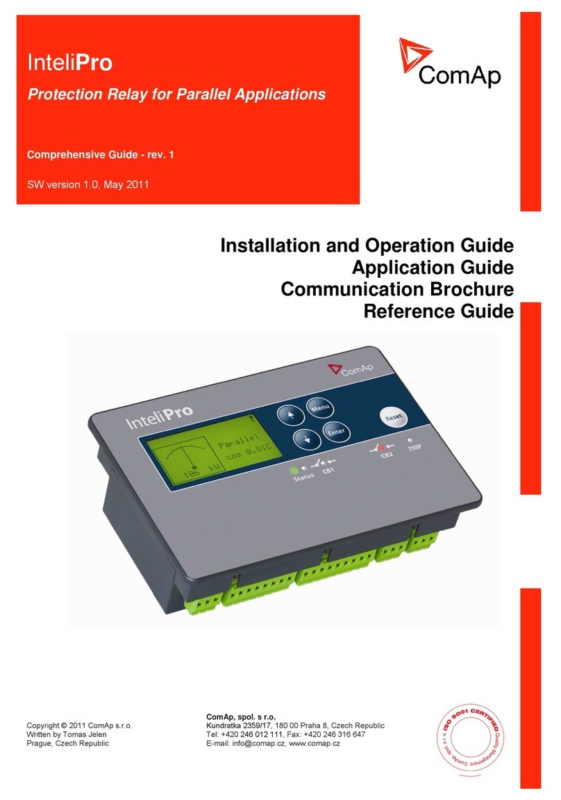
DIALOC LCS Pro Series User manual

User Manual
Version 1.14

LCS Pro units —User Manual Version 1.14
Page 2 of 43
©2004-2014 Dialoc ID. All rights reserved.
Dialoc ID makes no warranty of any kind with regard to this material, including, but not limited
to, the implied warranties of merchantability and fitness for a particular purpose.
Dialoc ID shall not be liable for errors contained herein or for incidental or consequential
damages in connection with the furnishing, performance, or use of this material.
Dialoc ID assumes no responsibility for the use or reliability of its equipment on equipment that
is not furnished by Dialoc ID.
Dialoc ID reserves the right to modify the software and hardware described in this manual at any
time without notice.
Trademarks:
Tattle Tape® is a registered trademark of 3M®.
Windows® is a registered trademark of Microsoft®.
This manual covers five LCS Pro units:
LCS Pro unit
Hardware
Firmware Subtype
LCS Pro EM
Standard parts LCS Pro unit *
+ EM (De)Activator
+ Serial cable
1.1
LCS Pro RFID
Standard parts LCS Pro unit
+ RFID controller
+ LCS Pro interface box
with three serial cables
1.2
LCS Pro Hybrid
Standard parts LCS Pro unit
+ EM (De)Activator
+ RFID controller
+ LCS Pro interface box
with three serial cables
1.3
LCS Pro RFID with Conversion
Standard parts LCS Pro unit
+ RFID controller
+ LCS Pro interface box
with three serial cables
+ Barcode scanner for conversion
1.6
LCS Pro Hybrid with Conversion
Standard parts LCS Pro unit
+ EM (De)Activator
+ RFID controller
+ LCS Pro interface box
with three serial cables
+ Barcode scanner for conversion
1.7

LCS Pro units —User Manual Version 1.14
Page 3 of 43
* Standard parts of an LCS Pro unit
Hardware version 03201114
Power supply
Boot version 0.18
Firmware LCSP, version 2.25
LCS Pro Control Program, version 2.25
Keyboard Wedge software, version 2.02
Optional part: Flush Mount device
Manual versions:
Version 1.0: first version
Version 1.01: Small details changed (LCS-pro control program V1.00)
Version 1.02: Small details changed
Version 1.03: Small details changed
Version 1.04: Test and configuration software added
User configurable commands added
Usage of CD security labels added
(LCS-pro control program V2.00)
Version 1.05: Save configuration option in LCS-pro control program added (LCS-pro
control program V2.01)
Version 1.06: Power cycling remark when firmware update doesn’t start automatically.
Version 1.07: Command to (de)activate repetitively added; (LCS-pro control program
V2.03)
Version 1.08: Pictures Flush Mount option added
Version 1.09: LCS-Pro Hardware version 03201114
Version 1.10: Hybrid and Conversion options added; LCS Pro Control Program V2.06
Version 1.11: LCS Pro Hybrid; LCS Pro Control Program V2.21
Version 1.12: 5 LCS Pro units; AFI-byte security added; LCS Pro Control Program V2.22
Version 1.13: Danish data model added in firmware and control program version 2.25
Version 1.14: Appendix C with explanation button lights added
Last version date: July 2014

LCS Pro units —User Manual Version 1.14
Page 4 of 43
Table of Contents
1Safety and precautions -------------------------------------------------------------------------------- 5
1.1 Do not touch internal parts ------------------------------------------------------------------------------------------------- 5
1.2 Grounding ---------------------------------------------------------------------------------------------------------------------- 5
1.3 Keep away from water ------------------------------------------------------------------------------------------------------ 5
1.4 Children------------------------------------------------------------------------------------------------------------------------- 5
1.5 Power cord/supply protection---------------------------------------------------------------------------------------------- 5
1.6 Environmental conditions--------------------------------------------------------------------------------------------------- 6
1.7 Cleaning ------------------------------------------------------------------------------------------------------------------------ 6
1.8 Magnetically sensitive materials ------------------------------------------------------------------------------------------ 6
1.9 Monitor interference---------------------------------------------------------------------------------------------------------- 7
1.10 Optical book sensor---------------------------------------------------------------------------------------------------------- 7
1.11 Installation---------------------------------------------------------------------------------------------------------------------- 7
2Product description------------------------------------------------------------------------------------- 8
2.1 LCS Pro units------------------------------------------------------------------------------------------------------------------ 8
2.2 Manual and Host Control Mode------------------------------------------------------------------------------------------- 9
2.3 Flush Mount device ---------------------------------------------------------------------------------------------------------- 9
3Tag placement and tag compatibility ------------------------------------------------------------11
3.1 EM tags ------------------------------------------------------------------------------------------------------------------------11
3.2 RFID tags----------------------------------------------------------------------------------------------------------------------11
4LCS Pro connections----------------------------------------------------------------------------------12
4.1 Installing the Barcode scanner-------------------------------------------------------------------------------------------14
4.2 Installing the “Software Keyboard Wedge” ----------------------------------------------------------------------------14
5Installing the “LCS Pro Control Program” -----------------------------------------------------16
5.1 “PC to LCS Pro Unit” Connection----------------------------------------------------------------------------------------16
5.2 Functions of LCS Pro Control Program, version 2.25 --------------------------------------------------------------16
6Configuring an LCS Pro unit------------------------------------------------------------------------17
6.1 LCS Pro Control Program -------------------------------------------------------------------------------------------------17
6.2 System Info Panel, Terminal Windows, Menus and Tabs---------------------------------------------------------19
6.3 Basic configuration options------------------------------------------------------------------------------------------------22
6.3.1 Manual Operation Mode or Host Control Mode------------------------------------------------------------------22
6.3.2 RFID Identification and Security-------------------------------------------------------------------------------------26
6.3.3 Item identifier conversion----------------------------------------------------------------------------------------------28
6.3.4 Data models --------------------------------------------------------------------------------------------------------------30
7LCS Pro Serial commands---------------------------------------------------------------------------33
7.1 Commands used by LCS Pro Configuration Program--------------------------------------------------------------33
7.2Commands used by Host system ---------------------------------------------------------------------------------------37
Appendix A - Specifications------------------------------------------------------------------------------39
Appendix B - Default settings LCS Pro units-------------------------------------------------------40
Appendix C –meaning of the status lights ---------------------------------------------------------42

LCS Pro units —User Manual Version 1.14
Page 5 of 43
1 Safety and precautions
Dear customer, we strongly recommend that you carefully study and follow the operating
instructions before attempting to operate the unit and that you note the listed precautions. Always
keep the instructions and the packaging so that if you relocate, sell, or give away this product,
you can give them to the new operator and/or owner.
1.1 Do not touch internal parts
Danger, high voltage exists inside this unit and inside the power supply, even after removing
the power.
This unit does not contain any user serviceable parts. Never open this unit or the power supply to
avoid personal injury and damage. Do not insert any object through the openings in this product
if not specifically advised to do so. Leave all repairs of this product to authorized and qualified
personal only. Should a repair be necessary, please contact Dialoc ID, or contact one of our
authorized service partners.
1.2 Grounding
Ensure this device is properly grounded. Electric shock could occur on an improperly grounded
device.
1.3 Keep away from water
Keep the unit away from flower vases, tubs, sinks, etc. If liquids are spilled into this unit, serious
damage and even personal injury could occur.
1.4 Children
Do not allow children to play unattended with electrical equipment. Children may not always
correctly recognize danger.
1.5 Power cord/supply protection
To avoid any malfunctions and to protect yourself against electric shock, fire or personal injury
please observe the following:
Please check the rated voltage on the power supply and compare this with the mains voltage
in your country.
When the product is not used for long times please disconnect the mains power.
Use only the power supply and power connection cable provided. Using a different power
supply will void your warranty and may cause serious damage.
Do not stretch the power cables tightly to reach a power outlet.
Arrange any cables attached to this equipment so that no one can trip over or step on them.
Hold the plug firmly when connecting or disconnecting the AC power cord.
Do not connect or disconnect the AC power cord when your hands are wet.
Keep the AC power cord and the power supply away from heating appliances
Never put any heavy object on the AC power cord.
Do not attempt to repair or reconstruct the AC power cord in any way.
Remove dust, dirt, etc. on the plug at regular intervals.

LCS Pro units —User Manual Version 1.14
Page 6 of 43
If the unit has been dropped or otherwise damaged, turn off the power and disconnect the
power supply.
If smoke, odours or unusual noises are emitted from the unit, turn off the power and
disconnect the power supply.
1.6 Environmental conditions
Avoid excessive dust, heat and direct sunlight.
Place and operate all units on a stable, flat and vibration-free surface.
Make sure this device and the power supply are subject to normal free air ventilation.
Do not block the ventilation slits of the Device, as this will cause heat to build up inside the
unit and may cause fire.
This device can be operated most reliable at ambient temperatures between +41°F and 95°F
(+5°C to +35°C) and at a relative humidity between 20% and 85% (not condensing). After
transporting the device from a cold to a warm environment please wait for 1-2 hours for
allowing the equipment to assume ambient temperature before connecting and switching it
on.
1.7 Cleaning
The cover should be cleaned by wiping with a dry cloth or slightly dampened with a mild
detergent solution. Never use thinner or any other volatile solvent on the plastic covers.
1.8 Magnetically sensitive materials
The LCS Pro EM unit, the LCS Pro Hybrid unit and the LCS Pro Hybrid with Conversion unit
consists of an EM Activator/Deactivator. When this EM (De)Activator device is used by an LCS
Pro unit for EM security it uses magnetic fields to activate (check-in) and deactivate (check-out)
magnetic security strips on printed materials.
This device is not designed nor suitable for processing magnetic media like magnetic tape
recordings and floppy discs. Trying to do so will most likely result in destroying the information
stored on the magnetic media. It will not destroy the magnetic media itself.
Keep magnetic sensitive materials and products like watches, magnetic media, bankcards and
credit cards at least 40 cm. away from an LCS Pro unit with EM security activated.

LCS Pro units —User Manual Version 1.14
Page 7 of 43
1.9 Monitor interference
When an LCS Pro unit is used for EM security the magnetic fields induced by the EM
(De)Activator may result in monitor interference when placed in close vicinity (<<1.5 meter) of
an obsolete CRT monitor (CRT, Cathode Ray Tube) or TV. During EM activation (check-in) or
EM deactivation (check-out) the screen may be distorted temporarily. This is not a
malfunctioning of the unit or the monitor/TV. However the strength of the effect will vary
between different types of monitors/tv’s. To avoid this, increase the distance between this device
and the monitor/TV.
An LCD monitor (TFT) will not be interfered by the LCS Pro unit.
1.10 Optical book sensor
LCS Pro units contain an optical sensor to detect whether or not a book is present in the book
area. Over time, this sensor might get filled with dust and other small particles. Clean the sensor
once a month with a dry cloth to make sure the unit still detects books properly.
The optical book sensor
1.11 Installation
Protecting yourself from injury and harm is absolutely imperative. We strongly suggest that
before you begin to maintain, install or service any of your appliances that you strictly adhere to
each of the following:
Always wear gloves. A sharp edge on an appliance can hurt and/or cut your hands.
Be sure to wear safety boots. You can cause serious injury to unprotected feet by dropping
any heavy appliances or tools.
Remember to remove any jewelry when servicing an appliance.
Make sure you use the correct tools and that they are clean and in good condition.
Abstain from putting your hands into any section of the appliance that you have not visually
inspected for jagged edges or sharp screws.
Inspect your work area to make sure it is clean and free of water or oil spills.
Ask for help if you need to move a heavy object.

LCS Pro units —User Manual Version 1.14
Page 8 of 43
2 Product description
2.1 LCS Pro units
LCS Pro unit
Functionality
LCS Pro EM
EM security
LCS Pro RFID
EAS-bit RFID security
AFI-byte RFID security
RFID item identification
LCS Pro Hybrid
EM security
EAS-bit RFID security
AFI-byte RFID security
RFID item identification
LCS Pro RFID with Conversion
EAS-bit RFID security
AFI-byte RFID security
RFID item identification
barcode to RFID conversion
Writing Library-ID (ISIL-number) into RFID tag
(Programming item-ID into RFID tag: only with
LCS Pro Control Program)
LCS Pro Hybrid with Conversion
EM security
EAS-bit RFID security
AFI-byte RFID security
RFID item identification
barcode to RFID conversion
Writing Library-ID (ISIL-number) into RFID tag
(Programming item-ID into RFID tag: only with
LCS Pro Control Program)
EM security Security by Activating or Deactivating an EM strip
EAS-bit RFID security Security by Setting or Resetting the EAS-bit of an RFID tag
AFI-byte RFID security Security by Setting the AFI (In or Out) byte of an RFID tag
RFID item identification Reading the item-ID from an RFID tag;
barcode to RFID conversion Scanning of the barcode on an item and writing the resulting
item-ID into the RFID tag on this item.
Writing ISIL-number Writing the library-ID (ISIL-number: International Standard
Identifier for Libraries and Related Organizations) into an RFID tag.

LCS Pro units —User Manual Version 1.14
Page 9 of 43
An LCS Pro unit consists of three backlit buttons: STATUS, LENDING
and RETURNING.
The Status button can illuminate with a green or red backlight. A green backlight signals that the
unit is switched on. When a red Status backlight is shown, its meaning depends on the
configuration of the unit (See chapter 6.3.1).
The Status button can be configured as a power on/off switch. In this case pressing the Status
button on a unit with power on will switch power off, and reverse.
The Lending end Returning buttons are used for executing respectively a deactivation command
or an activation command. A blue backlight on one of these buttons indicates the type of
command that has been or will be given.
Both buttons only have a function when a unit is in manual control mode (See chapter 2.2)
2.2 Manual and Host Control Mode
A unit can be configured for Manual Control Mode or for Host Control Mode.
In Manual Control Mode the Lending or the Returning button of a unit needs to be pressed to
generate respectively a deactivation or activation command.
In Host Control Mode, the LCS Pro unit receives a deactivation or activation command from a
host terminal. In this mode the Lending and Returning buttons are disabled and the backlights of
these buttons are turned off.
A unit can only function in Host Control Mode if a host terminal is capable of generating the
required activation and deactivation commands.
2.3 Flush Mount device
Optionally, a flush mount device is available to build an LCS Pro Hybrid into furniture.

LCS Pro units —User Manual Version 1.14
Page 10 of 43

LCS Pro units —User Manual Version 1.14
Page 11 of 43
3 Tag placement and tag compatibility
3.1 EM tags
EM security tags should be placed in the spine of the book, within18 cm from the top of the
book. This is important for the status indicator to work properly.
The LCS Pro Hybrid can activate and deactivate most EM security tags commonly used in
libraries, like the DIALOC ID chip tags, DIALOC ID tail tags and the 3M Tattle tape®. If you
have any compatibility doubts here, please contact your dealer.
3.2 RFID tags
The preferred RFID Tag location on a book is inside the back cover and near the spine of the
book.
In fact an RFID Tags can be put on any place on a book as long as the RFID antenna can read the
tag. But, when RFID tags are also used for shelf reading with a portable reader then to have all
RFID tags near the spine of the book and on different heights (at least 6 cm from the shelve in
case of metal shelves) is more favorable.
The LCS Pro RFID or Hybrid units operates for identification only with ISO 15693 tags.
The LCS Pro RFID or Hybrid units can only perform EAS-bit security with ICODE SLI tags.
AFI-byte security can be performed with every 15693 tag that supports AFI.

LCS Pro units —User Manual Version 1.14
Page 12 of 43
4 LCS Pro connections
An LCS Pro RFID and Hybrid unit can perform more functions than an LCS Pro EM unit. This
requires additional COM ports on both the LCS Pro and the Host terminal. The extra COM ports
needed on the LCS Pro Hybrid are housed in a separate LCS Pro Interface Box.
The LCS Pro Interface Box contains four COM ports labelled as “LCS Pro”, “PC”, “Wedge” and
“Barcode”. The picture below shows the LCS Pro Hybrid with Conversion, the LCS Pro
Interface Box and a Host terminal with their interconnections.
The serial cable between the LCS Pro unit and the Interface Box consists of RJ12 jacks on both
sides of the cable. On the LCS Pro unit the cable needs to be connected to the RJ12 receptacle
named “HOST” located at the bottom of the unit. On the Interface Box the cable needs to be
connected to the receptacle named “LCS Pro”.
The RJ12 jacks have to be wired according to the table below.
The RX line of an LCS Pro unit has to be connected to the TX line of the Interface Box. Vice
versa, the TX line of the LCS Pro unit has to be connected to the RX line of the Interface Box.
Both signal grounds and Power, from the LCS Pro unit and the Interface Box, must be tied
together.
Note
Only the LCS Pro EM unit is delivered without an LCS Pro Interface Box. To be able to
configure the LCS Pro EM unit and to function in Host Control Mode a serial cable is delivered
to connect the LCS Pro EM unit with the Host terminal. On the LCS Pro EM unit the cable needs
to be connected to the RJ12 receptacle named “HOST” located at the bottom of the unit. On the
Host terminal the cable needs to be connected to a COM port.
LCS Pro
Interface Box
Host Terminal
RJ12 pin
Function
RJ12 pin
9p Sub D
1
NC
2
RX (in)
2 –TX
3 –TX
3
TX (out)
3 –RX
2 –RX
4
NC
5
Signal
ground
5 –GND
5 –GND
6
Power
6

LCS Pro units —User Manual Version 1.14
Page 13 of 43
The two serial cables between LCS Pro Interface Box and Host terminal do have 9-pin Sub-D
connectors on both sides of a cable. In case only USB connectors and no COM ports are
available on the Host terminal then a 9-pin SUB-D to USB adapter can be used in between cable
and Host terminal. These adaptors are generally available and will not be delivered by Dialoc ID
as part of an LCS Pro unit.
Connection A is used for barcode to RFID conversion.
Connection B is necessary for Host Control Mode. Over this connection the Host terminal send
(de)activate commands to the LCS Pro unit.
Connection C is used to send the item-ID, that is read from the RFID tag, from the LCS Pro unit
to the Host terminal. On the terminal the item-ID is “seen” as a keyboard input due to the
D
C
A
D
B

LCS Pro units —User Manual Version 1.14
Page 14 of 43
software keyboard wedge that is configured on the receiving COM port. (See section 4.1 for
Installing the software keyboard wedge.)
Connection D is used by LCS Pro to send responses to the Host terminal on terminal commands.
This connection is also used during configuration of an LCS Pro unit.
4.1 Installing the Barcode scanner
The barcode scanner is used to read the barcodes from and write these codes to the RFID labels
(the conversion). The barcode scanner has to have a serial interface and shall be able to be used
in a stand-alone mode, that is: either when a button on the scanner is pressed or when a barcode
is presented to the reader it shall send the barcode over the serial port, ending with a <CR>.
The baudrate has to be the same as the baudrate of the LCS pro.
See the manual of the barcode scanner for information on the configuration.
4.2 Installing the “Software Keyboard Wedge”
Attention
With the Keyboard Wedge installed and active, the Host terminal can “see” an RFID Item-ID as
a keyboard input. Installing and activating the Keyboard Wedge is only relevant for LCS Pro
units with the RFID option activated.
The Software Keyboard Wedge program (version 2.02) will be installed automatically during
installation of the LCS Pro Control Program. This program is also available on the “LCS Pro
units CD-ROM, version 2.25”, (Keyboard-wedge_setup_V1.00.exe) for a separate installation on
the host terminal.
Click on StartProgramsDialoc IDLCS ProKeyboard Wedge to activate the program.
When the program can’t make a connection an Xappears in the Notification area down right on
the desktop.
At the same time an error message appears followed by a configuration window in which the
correct COM port can be chosen.

LCS Pro units —User Manual Version 1.14
Page 15 of 43
When connected a √ appears in the Notification area.
After a Right Mouse Click on the Keyboard Wedge Icon the program can be closed (Exit) or the
configuration window can be opened (Setup).
When checking the option “Run At Windows Start Up” on the configuration window the
Keyboard Wedge will be activated during Windows startup.

LCS Pro units —User Manual Version 1.14
Page 16 of 43
5 Installing the “LCS Pro Control Program”
The installation file “Setup LCS-Pro control program V2.25.zip” can be found on the “LCS Pro
units CD-ROM, version 2.25”.
Install the LCS-Pro control program on the Host Terminal or on a Test PC, preferable a laptop.
The LCS Pro Control Program will be installed default in the folder C:\Program Files\Dialoc
ID\LCS_Pro. It works under MS-Windows XP, Vista and Windows 7.
By checking “Launch LCS Pro” and/or checking “Launch GPkey” before finishing the
installation, the LCS Pro or the Keyboard Wedge or both programs will be launched after
finishing the installation.
5.1 “PC to LCS Pro Unit” Connection
To be able to configure an LCS Pro unit with the LCS Pro Control Program, the Host terminal or
the Test PC needs to be connected to the “Host” connection on the LCS Pro unit or connected to
the PC connection on the LCS Pro Interface box.
5.2 Functions of LCS Pro Control Program, version 2.25
oconfigure LCS Pro units
odisplay and print the current LCS Pro configuration
oprogram an item-ID into an RFID tag
oemulate communication (commands to and responses from an LCS Pro unit) between
LCS Pro unit and host computer
oupdate the LCS Pro firmware and firmware subtypes

LCS Pro units —User Manual Version 1.14
Page 17 of 43
6 Configuring an LCS Pro unit
6.1 LCS Pro Control Program
Attention
Close (Exit) an active Keyboard Wedge before using LCS Pro Control Program.
Click on the “Get Current Settings” button after opening the LCS Pro Control Program.
In case this button is not active (ghosted; greyed) then select a COM-port first.
Click on “Select Com Port” button

LCS Pro units —User Manual Version 1.14
Page 18 of 43
After the COM port has been selected on which the LCS Pro unit is connected, the “Power On”
checkbox and the “Get Current Settings” button will be available.
“Power On” Checkbox
When “Power On” is checked the remaining checkboxes and buttons on the “Common” tab
become available.
“Get Current Settings” button
After pressing the “Get Current Settings” button, the power of the LCS Pro unit is switched on
(Status button of LCS Pro unit lights up green and the “Power On” checkbox is marked), the
current configuration of the LCS Pro unit is imported in the Control Program and the remaining
buttons and options become available depending on the specific hardware and software subtype
on the current LCS Pro unit.
Keyboard entry
When no mouse but only a keyboard is available, use the Tab-key to select a button and the
Insert-key to press a button.

LCS Pro units —User Manual Version 1.14
Page 19 of 43
6.2 System Info Panel, Terminal Windows, Menus and Tabs
System Info Panel
This panel displays the current system information of the LCS Pro unit.
Terminal Windows
All external control of the LCS Pro unit is done by sending human readable commands (ASCII)
to and from the unit. This communication can be watched in the LCS Pro Control Program. Two
terminal windows show the characters sent to (bottom window; white background) and received
from the LCS Pro unit (top screen; blue background).
In the example above the responses are shown that are received from the LCS Pro unit after
sending the command “Get system info” to the unit.

LCS Pro units —User Manual Version 1.14
Page 20 of 43
Menus:
File menu
LCS Pro settings can be stored in a configuration file (*.set).
With the file menu options a configuration file can be imported into or saved from the LCS Pro
Control Program. Also, LCS Pro settings can be printed.
Options menu
With the option “Clear Terminal” both terminal windows can be cleared.
When “Enable terminal input” is checked then commands can be send to the LCS Pro by typing
in these commands in the 'Characters sent to the LCS-pro' window. This option can be used to
check new host commands.
Help menu
The “Contents” option of the Help menu activates the online Help file.
The “About…” option of the Help menu shows the current version of the LCS Pro Control
Program.
Tabs:
The LCS Pro configuration options and Control Program commands are placed on different tabs.
Common Tab:Tab consists of general configuration options, program commands and manual
operation mode options.
Host Tab: Tab consists of Host mode configuration options.
RFID Tab: Tab consists of RFID configuration options.
This tab lacks if the LCS Pro Configuration Program is used with the LCS Pro EM
Unit.
Common Tab buttons
Reads current system information from the LCS Pro unit and displays
this information in the System Info Panel
Reads all current configuration settings from the LCS Pro unit and
sets up the configuration options of the LCS Pro Control Program in
accordance with these settings. At the same time the system
information is read from the LCS Pro unit and displayed in the
System Info Panel.
Resets the LCS Pro unit to its factory (default) settings.
(See: Appendix B –Default settings LCS Pro units)
This manual suits for next models
3
Table of contents


