Dialog Semiconductor DA14580 User manual

User manual
DA14580/581/583 Bluetooth
Smart development Kit – Pro
UM-B-034
Abstract
This document describes the Bluetooth Smart Development Kit - Pro based on
DA14580/DA14581-01/DA14583.
It helps users to set up the hardware development environment, install required software and quickly
start product development with help of example source codes.
UM-B-034
DA14580/581/583 Bluetooth Smart development Kit –Pro
User manual
Revision 1.4
31-jan-2016
CFR0012 Rev 3
2 of 49
© 2016 Dialog Semiconductor
Contents
Abstract................................................................................................................................................ 1
Contents............................................................................................................................................... 2
Figures.................................................................................................................................................. 3
Tables ................................................................................................................................................... 3
1Terms and definitions................................................................................................................... 4
2References..................................................................................................................................... 4
3Introduction.................................................................................................................................... 5
3.1 Hardware content.................................................................................................................. 6
3.2 Web content.......................................................................................................................... 8
3.2.1 Software Development Kit content ........................................................................ 8
3.2.1.1 Tools.................................................................................................. 8
3.2.1.2 SDK documents................................................................................. 8
3.2.1.3 SDK source code examples (created in Keil).................................... 9
3.3 DA14580 - DA14581 Pro kit................................................................................................ 11
3.3.1 Differences between the DA14580, DA14581 and DA14583.............................. 11
3.4 Pinning ................................................................................................................................ 13
3.4.1 PCB design and functionalities............................................................................ 14
3.4.2 Configuring the Pro kit-board by jumper settings ................................................ 15
3.4.3 Block diagram...................................................................................................... 17
4Installation of tools and drivers................................................................................................. 18
4.1 Keil ...................................................................................................................................... 18
4.2 SEGGER Jlink driver........................................................................................................... 19
4.3 FTDI driver .......................................................................................................................... 20
4.4 Tera Term ........................................................................................................................... 20
5Memory and tools........................................................................................................................ 21
6Using the demo kit ...................................................................................................................... 22
6.1 Run an example on DA14580/581/583............................................................................... 22
Layout............................................................................................................................ 27
Connections of J7 and J8............................................................................................ 27
Schematics Motherboard and Daughterboards........................................................ 28
C.1 Peripherals.......................................................................................................................... 28
C.2 SPI and serial...................................................................................................................... 29
C.3 Current measurement......................................................................................................... 30
C.4 JTAG Interface.................................................................................................................... 31
C.5 PCI-e................................................................................................................................... 32
C.6 Power supplies.................................................................................................................... 33
C.7 USB HUB Controller............................................................................................................ 34
C.8 DA14580 WLCSP Daughter board ..................................................................................... 35
C.9 DA14580 QFN40 Daughterboard ....................................................................................... 36
C.10 DA14580 QFN48 Daughterboard ....................................................................................... 37
C.11 DA14581 WLCSP Daughterboard ...................................................................................... 38
C.12 DA14581 QFN40 Daughterboard ....................................................................................... 39
C.13 DA14583 QFN40 Daughterboard ....................................................................................... 40

UM-B-034
DA14580/581/583 Bluetooth Smart development Kit –Pro
User manual
Revision 1.4
31-jan-2016
CFR0012 Rev 3
3 of 49
© 2016 Dialog Semiconductor
Using the SmartSnippets CLI...................................................................................... 41
Opening your project for the first time....................................................................... 42
Latency Timer of FTDI cable........................................................................................ 43
RF-Testing DEVKT - Pro.............................................................................................. 44
Battery connection ‘workaround’ ............................................................................... 47
7Web-Link ...................................................................................................................................... 48
8Revision history .......................................................................................................................... 48
Figures
Figure 1: DA14580/581 - Pro kit............................................................................................................ 6
Figure 2: DA14583 - Pro Kit .................................................................................................................. 6
Figure 3: QFN40 pin assignment from datasheet ............................................................................... 13
Figure 4: DA14580 Development Kit –Pro (PCB topview)................................................................. 14
Figure 5: DA14580/581/583 (Fabrication default) UART boot settings (T_TxD P0_5 and T_RxD
P0_4)................................................................................................................................................... 15
Figure 6: DA14580/581 Boot from external SPI memory.................................................................... 15
Figure 7: DA14583 Boot from internal SPI memory............................................................................ 16
Figure 8: Layout of headers J5 and J6................................................................................................ 16
Figure 9: UART Data Direction of Uart within J5................................................................................. 16
Figure 10: Block diagram of total system ............................................................................................ 17
Figure 11: DA14580/581/583 block diagram....................................................................................... 21
Figure 12: Board layout....................................................................................................................... 27
Figure 13: IO breakout available on QFN40 and QFN48.................................................................... 27
Figure 14: IO breakout available on QFN48........................................................................................ 27
Figure 15: Peripherals schematic of Motherboard .............................................................................. 28
Figure 16: SPI and serial schematic of Motherboard.......................................................................... 29
Figure 17: Current measurement schematic of Motherboard ............................................................. 30
Figure 18: JTAG interface schematic of Motherboard ........................................................................ 31
Figure 19: PCI-e schematic of Motherboard ....................................................................................... 32
Figure 20: Power supplies schematics of Motherboard ...................................................................... 33
Figure 21: USB HUB controller schematic of Motherboard................................................................. 34
Figure 22: DA14580 WLCSP Daughter board .................................................................................... 35
Figure 23: DA14580 QFN40 Daughterboard....................................................................................... 36
Figure 24: DA14580 QFN48 Daughterboard....................................................................................... 37
Figure 25: DA14581 WLCSP Daughterboard ..................................................................................... 38
Figure 26: DA14581 QFN40 Daughterboard....................................................................................... 39
Figure 27: DA14583 QFN40 Daughterboard....................................................................................... 40
Figure 28: Open the CLI of SmartSnippets......................................................................................... 41
Figure 29: Smart snippet CMD window............................................................................................... 41
Figure 30: FTDI Latency Timer ........................................................................................................... 43
Figure 31: Reset circuitry. R84 to be dismounted............................................................................... 47
Figure 32: Location of R84.................................................................................................................. 47
Tables
Table 1: Content of the DA14580/581/583 Pro Kit................................................................................ 7
Table 2: DA14580................................................................................................................................ 11
Table 3: DA14581................................................................................................................................ 11
Table 4: DA14583................................................................................................................................ 12
Table 5: SPI connections..................................................................................................................... 13
Table 6: Installation tools and drivers.................................................................................................. 18
Table 7: Run an example on DA14580/581/583................................................................................. 22

UM-B-034
DA14580/581/583 Bluetooth Smart development Kit –Pro
User manual
Revision 1.4
31-jan-2016
CFR0012 Rev 3
4 of 49
© 2016 Dialog Semiconductor
1 Terms and definitions
BLE Bluetooth Low Energy
CS Chip Select
DK Development Kit
EEPROM Electrically Erasable Programmable Memory
FTDI Brand name of USB –UART interface
GPIO General Purpose Input Output
OTP One Time Programmable
PCB printed circuit board
QFN Quad-Flat No-leads
SDK Software Development Kit
SPI Serial Peripheral Interface
SRAM Static Random Access Memory
SWD Serial Wire Debug
USB Universal Serial Bus
UART Universal Asynchronous Receiver/Transceiver
WLCSP Wafer Level Chip Scale Packaging
WoW Way of Working
2 References
1. DA14580, Datasheet, Dialog Semiconductor
2. DA14581, Datasheet, Dialog Semiconductor
3. UM-B-015, DA14580_581_583 Software Architecture, Dialog Semiconductor
4. DA14580_CB PXI QFN40 layout, Dialog Semiconductor
5. DA14580_CB_PXI_QFNP40, Dialog Semiconductor
6. DA14580_CB_PXI_WLCSP, Dialog Semiconductor
7. DA14580_CB_PXI_WLCSP_layout, Dialog Semiconductor
8. DA14580_MB_VB_layout, Dialog Semiconductor
9. DA14580_CB PXI_QFN48, Dialog Semiconductor
10. UM-B-005, DA14580_581_583 Peripheral Examples, Dialog Semiconductor
11. UM-B-010, DA14580_581_583 Proximity application, Dialog Semiconductor
12. AN-B-015, DA14580 Supply current measurement, Dialog Semiconductor

UM-B-034
DA14580/581/583 Bluetooth Smart development Kit –Pro
User manual
Revision 1.4
31-jan-2016
CFR0012 Rev 3
5 of 49
© 2016 Dialog Semiconductor
3 Introduction
DA14580/581/583 is a Bluetooth Smart chip, working with extremely low power while providing
world-class RF performance, a small footprint and flexible peripheral configurations for a wide range
of applications. The development kit includes a set of hardware (e.g. development board with on-
board debugger), a Software Development Kit (SDK) (e.g. development tools, source code examples
documents and so on) along with documentation. This document helps users to set up
hardware/software development environment, install required software and quickly start product
development with the help of example source code.
Web content can be downloaded at:
www.dialog-semiconductor.com/support.
Product information about the DA14580/581/583 can be found at:
http://www.dialog-semiconductor.com/products/bluetooth-smart
Product information about the DA14580/581/583 Development Kit - Pro can be found at:
http://www.dialog-semiconductor.com/products/bluetooth-smart/smartbond-development-
tools/da14580-development-kit-pro
The DA14583 is DA14580 plus 1Mbit SPI memory in same package.

UM-B-034
DA14580/581/583 Bluetooth Smart development Kit –Pro
User manual
Revision 1.4
31-jan-2016
CFR0012 Rev 3
6 of 49
© 2016 Dialog Semiconductor
3.1 Hardware content
In Figure 1 and Figure 2 the kit components are shown and Table 1 contains an overview the parts.
Optional* Optional*
DA14581 Pro kitDA1580 Pro kit
Figure 1: DA14580/581 - Pro kit
Optional*
DA14583 Pro kit
Figure 2: DA14583 - Pro Kit

UM-B-034
DA14580/581/583 Bluetooth Smart development Kit –Pro
User manual
Revision 1.4
31-jan-2016
CFR0012 Rev 3
7 of 49
© 2016 Dialog Semiconductor
Table 1: Content of the DA14580/581/583 Pro Kit
DA14580/581/583 DEVKT –PRO:
Included
in the kit
Separate
option for
the 580 kit*
Separate
option for
the 581 kit*
Separate
option for
the 583 kit*
Battery CR2032
X
Mini USB Cable
X
DA14580A3DB-P (QFN48)
X
DA14580ATDB-P (QFN40)
X
DA14580UNDB-P (WL-CSP)
X
DA14581UNDB-P (WL-CSP)
X
DA14581ATDB-P (QFN40)
X
DA14583ATDB-P (QFN40)
X
DA14580DEVKT-P_VB (Main board)**
X
USB Dongle
X
Note 1 * Not included in the kit, must be bought separately.
Note 2 ** The mainboard is compatible with all boards.

UM-B-034
DA14580/581/583 Bluetooth Smart development Kit –Pro
User manual
Revision 1.4
31-jan-2016
CFR0012 Rev 3
8 of 49
© 2016 Dialog Semiconductor
3.2 Web content
3.2.1 Software Development Kit content
3.2.1.1 Tools
Web-link: www.dialog-semiconductor.com/support
SmartSnippets
SmartSnippets is a framework of PC based tools to control DA14580/581/583 development kit,
consisting of:
●Power Profiler : Real time current consumption measurement to for the DA14580/581/583
motherboard
●OTP Programmer: Tool for OTP memory programming
●UART/JTAG booter: Tool for downloading hex files to DA14580/581/583 SRAM over UART or
JTAG
●SPI & EEPROM programmer: A tool for SPI & EEPROM flash programming
●Sleep Mode Advisor: Calculation tool to determine most optimal sleep modes
ConnectionManager
ConnectionManager is a PC based software tool to control the link layer of the DA14580/581/583
with the following capabilities:
●Functional in Peripheral and Central role
●Set advertising parameters
●Set connection parameters
●Reading from Attribute database
●Perform production test commands
3.2.1.2 SDK documents
●UM-B-003, DA14580_581_583 Software development guide
●UM-B-004, DA14580_581_583 Peripheral drivers
●UM-B-005, DA14580_581_583 Peripheral examples
●UM-B-006, DA14580 Sleep mode configuration
●UM-B-007, DA14580 Software Patching over the Air (SPOTA)
●UM-B-008, DA14580 Production test tool
●UM-B-010, DA14580_581_583 Proximity application
●UM-B-011, DA14580 Memory map –scatter file
●UM-B-012, DA14580 Secondary boot loader
●UM-B-013, DA14580 External Processor Interface over SPI
●UM-B-014, DA14580 Bluetooth Smart Development Kit - Expert
●UM-B-015, DA14580_581_583 Software architecture
●UM-B-016, DA14580 Software Porting Guide
●UM-B-017, DA14580 GTL interface Integrated Processor Application

UM-B-034
DA14580/581/583 Bluetooth Smart development Kit –Pro
User manual
Revision 1.4
31-jan-2016
CFR0012 Rev 3
9 of 49
© 2016 Dialog Semiconductor
3.2.1.3 SDK source code examples (created in Keil)
●dk_apps. This folder holds all the necessary folders needed for DA14580/581/583 application
development.
odk_apps\keil_projects\proximity:
The folder contains the following subfolders and in each one of them resides the respective
project file:
Table 1: SDK Examples
Folder
Project File
Description
prox_monitor_ext\Keil_4
prox_monitor_ext\Keil_5
prox_monitor_ext.uvproj
prox_monitor_ext_581.uvproj
prox_monitor_ext_583.uvproj
prox_monitor_ext.uvprojx
prox_monitor_ext_581.uvprojx
prox_monitor_ext_583.uvprojx
Proximity Monitor (External processor
configuration)
prox_reporter_ext\Keil_4
prox_reporter_ext\Keil_5
prox_reporter_ext.uvproj
prox_reporter_ext_581.uvproj
prox_reporter_ext_583.uvproj
prox_reporter_ext.uvprojx
prox_reporter_ext_581.uvprojx
prox_reporter_ext_583.uvprojx
Proximity Reporter (External processor
configuration)
prox_reporter\Keil_4
prox_reporter\Keil_5
prox_reporter.uvproj
prox_reporter_581.uvproj
prox_reporter_583.uvproj
prox_reporter.uvprojx
prox_reporter_581.uvprojx
prox_reporter_583.uvprojx
Proximity Reporter (Integrated
processor configuration)
prox_monitor_ext_usb\Keil_4
prox_monitor_ext_usb\Keil_5
prox_monitor_ext_usb.uvproj
prox_monitor_ext_usb_581.uvproj
prox_monitor_ext_usb_583.uvproj
prox_monitor_ext_usb.uvprojx
prox_monitor_ext_usb_581.uvprojx
prox_monitor_ext_usb_583.uvprojx
Proximity Monitor (External processor
configuration)
Version for USB dongle
prox_reporter_ext_usb\Keil_4
prox_reporter_ext_usb\Keil_5
prox_reporter_ext_usb.uvproj
prox_reporter_ext_usb _581.uvproj
prox_reporter_ext_usb _583.uvproj
prox_reporter_ext_usb.uvprojx
prox_reporter_ext_usb
_581.uvprojx
prox_reporter_ext_usb
_583.uvprojx
Proximity Reporter (External processor
configuration)
Version for USB dongle
prox_reporter_ext_spi\Keil_4
prox_reporter_ext_spi\Keil_5
prox_reporter_ext_spi.uvproj
prox_reporter_ext_spi_581.uvproj
prox_reporter_ext_spi_583.uvproj
prox_reporter_ext_spi.uvprojx
prox_reporter_ext_spi_581.uvprojx
prox_reporter_ext_spi_583.uvprojx
Proximity Reporter (External processor)
SPI version

UM-B-034
DA14580/581/583 Bluetooth Smart development Kit –Pro
User manual
Revision 1.4
31-jan-2016
CFR0012 Rev 3
10 of 49
© 2016 Dialog Semiconductor
odk_apps\keil_projects\prod_test: These folders include the source code of the production
test firmware. Refer to DA14580_581_583 _Production_Test_Tool.docx for more information
how to build and use it.
odk_apps\keil_projects\template: These folders include a template as a starting point of a
new application.
For details, please read [9].
●host_apps: This folder holds the DA14580/581/583 PC applications:
ohost_apps\windows\proximity: The folder includes two Windows C++ applications, with
each one acting as part of a proximity monitor and a proximity reporter application. They are
placed in subfolders monitor and reporter respectively.
For details, please read the DA14580_581_583 Proximity Application Guide.
ohost_binaries\windows\proximity: The folder includes two pre-compiled Windows
executables which correspond to the C++ applications described right above and are
included for user convenience.
operipheral_examples: The folder includes sample code of how to use peripheral blocks of
the DA14580/581/583 (e.g. UART, SPI, I2C etc.) bundled to a demo-kit.
For details, please refer to [10].
●Tools:
otools\prod_test\prod_test_cmds: This folder includes the source code of the production
test tool. Refer to DA14580/DA14581_Production_Test_Tool.docx for more information how
to build and use it.

UM-B-034
DA14580/581/583 Bluetooth Smart development Kit –Pro
User manual
Revision 1.4
31-jan-2016
CFR0012 Rev 3
11 of 49
© 2016 Dialog Semiconductor
3.3 DA14580 - DA14581 Pro kit
3.3.1 Differences between the DA14580, DA14581 and DA14583
The only hardware difference between the daughter boards of the DEVKT-Pro 14580 and the
DEFKT-Pro 14581, is the design in of QFN48 (580) and the QFN40 (581). The silkscreen may have
small textual differences.
The DA14581 uses a dedicated ROM which offers optimisations targeting A4WP and HCI.
Table 2: DA14580
Product
Memory size
General
Purpose
I\O’s
Package
Key Features
Applications
WLCSP34
ROM
84kBytes
OTP
32kBytes
RAM
50kBytes
12
2.5x2.5x0.5mm,
pitch 0.4mm
Bluetooth 4.0
+ 4.1
Cortex M0
application
processor
Power supply
0.9 -3.3V
Single pin RF
I/O
Rich set of
analog and
digital
peripherals
Beacon &
Proximity
Health &
Fitness
HID
Smart Home
QFN40
24
5x5x0.9mm,
pitch 0.4mm
QFN48
32
6x6x0.9mm,
pitch 0.4mm
Table 3: DA14581
Product
Memory size
General
Purpose
I\O’s
Package
Key Features
Applications
WLCSP34
ROM
84kBytes
OTP
32kBytes
RAM
50kBytes
12
2.5x2.5x0.5mm,
pitch 0.4mm
Bluetooth 4.0
+ 4.1
Cortex M0
application
processor
Power supply
0.9 -3.3V
Single pin RF
I/O
Rich set of
analog and
digital
peripherals
8 connections
Optimized
boot time
Wireless
charging
(A4WP)
HCI
QFN40
24
5x5x0.9mm,
pitch 0.4mm
UM-B-034
DA14580/581/583 Bluetooth Smart development Kit –Pro
User manual
Revision 1.4
31-jan-2016
CFR0012 Rev 3
12 of 49
© 2016 Dialog Semiconductor
Table 4: DA14583
Product
Memory size
General
Purpose
I\O’s
Package
Key Features
Applications
ROM
84kBytes
OTP
32kBytes
RAM
50kBytes
Bluetooth 4.0
+ 4.1
Cortex M0
application
processor
Power supply
2.35 -3.3V
Single pin RF
I/O
Rich set of
analog and
digital
peripherals
Beacon &
Proximity
Health &
Fitness
HID
Smart Home
QFN40
24
5x5x0.9mm,
pitch 0.4mm
A4WP wireless charging features:
oFast boot time for Power Receiving Unit (PRU)
o8 connections for Power Transmitting Unit (PTU)
HCI features:
oOptimized code for HCI which fits into the OTP
oThis enables customers/modules makers to provide a pre-programmed HCI module
Remark: DA14583 will run in BUCK mode only!

UM-B-034
DA14580/581/583 Bluetooth Smart development Kit –Pro
User manual
Revision 1.4
31-jan-2016
CFR0012 Rev 3
13 of 49
© 2016 Dialog Semiconductor
3.4 Pinning
In Figure 3 the pinout of the DA14583 is shown. New, compared to the DA14580/581, are the
connections to the internal SPI flash memory.
Figure 3: QFN40 pin assignment from datasheet
Table 5: SPI connections
port
DA14583
function
remark
P2_0
SPI_CLK
SCLK (Note 1)
P2_9
SPI_DI
MOSI (Note 1)
P2_4
SPI_DO
MISO (Note 1)
P2_3
SPI_EN
not to be used for external SPI (!)
VCC_FLASH
power for internal Flash Memory
GND
Note 1 shared with internal flash memory
When external SPI components are used, SPI_EN is occupied for internal use. Another pin should
be chosen for SPI_EN of the external component.
By using a Secondary Bootloader the proper pins are programmed to load the booting software from
the SPI-memory at startup.

UM-B-034
DA14580/581/583 Bluetooth Smart development Kit –Pro
User manual
Revision 1.4
31-jan-2016
CFR0012 Rev 3
14 of 49
© 2016 Dialog Semiconductor
3.4.1 PCB design and functionalities
The top-screen layer of the pro kit PCB is shown below in Figure 4.
Figure 4: DA14580 Development Kit –Pro (PCB topview)

UM-B-034
DA14580/581/583 Bluetooth Smart development Kit –Pro
User manual
Revision 1.4
31-jan-2016
CFR0012 Rev 3
15 of 49
© 2016 Dialog Semiconductor
3.4.2 Configuring the Pro kit-board by jumper settings
There are two configurations that can be switched; the default configuration that supports the boot
from UART or the configuration that supports boot from an external SPI flash memory.
The jumper settings are displayed below.
LEDTriggers VPP
Current measurement
BATT/USB
RxD (P0_4)
TxD (P0_5)
CTS (P0_6)
RTS (P0_7)
T_TMS (SWDIO)
T_TCK (SWCLK)
Figure 5: DA14580/581/583 (Fabrication default)
UART boot settings (T_TxD P0_5 and T_RxD P0_4)
LEDTriggers VPP
Current measurement
BATT/USB
SPI_MISO (P0_5)
SPI_MOSI (P0_6)
SPI_CS (P0_3)
SPI_CLK (P0_0)
SPI_SUP (BAT_SEL)
T_TMS (SWDIO)
T_TCK (SWCLK)
Figure 6: DA14580/581 Boot from external SPI memory
Note 2 These functionalities are shown in detail in Appendix A

UM-B-034
DA14580/581/583 Bluetooth Smart development Kit –Pro
User manual
Revision 1.4
31-jan-2016
CFR0012 Rev 3
16 of 49
© 2016 Dialog Semiconductor
T_TCK (SWCLK)
T_TMS (SWDIO)
SPI_SUP (BAT_SEL)
VPP
LED
Triggers
Current measurement
BATT/USB
Figure 7: DA14583 Boot from internal SPI memory
SWCLK
SPI_SUPPLY
SWDIO
T_RxD
T_CTS
T_RTS
SPI_CS
SPI_CLK
P0_1
T_TxD
P1_0
P1_2
gnd
gnd
VBAT_580
RST
P1_3
P1_1
P0_2
P0_4
P0_5
P0_6
P0_7
P0_3
P0_0
BATT SEL
T_TMS
T_TCK
Pin 1.
Figure 8: Layout of headers J5 and J6
P0_4 (TxD)
P0_5 (RxD)
P0_6 (RTS)
P0_7 (CTS)
(TxD)
(CTS)
(RTS)
(RxD)
USB
DA14580/581/583
Figure 9: UART Data Direction of Uart within J5
Example: when jumper J5 (27-28) is placed, connection ‘T_TCK = SWCLK’ is made.
In Figure 5 and Figure 6 the connections are added next to the arrows.
On this board only the buck mode is used. A choice can be made between 3V3 (via USB: J11 1-2) or
Vdd (a coin cell: J11 2-3). No battery is needed when running via the USB-mini-cable.
Remark: For proper battery functionality a small modification should be made. For the details see the
workaround in Appendix H.

UM-B-034
DA14580/581/583 Bluetooth Smart development Kit –Pro
User manual
Revision 1.4
31-jan-2016
CFR0012 Rev 3
17 of 49
© 2016 Dialog Semiconductor
3.4.3 Block diagram
This is the schematic of the block diagram; all other schematics can be found in Appendix C.
Figure 10: Block diagram of total system
UM-B-034
DA14580/581/583 Bluetooth Smart development Kit –Pro
User manual
Revision 1.4
31-jan-2016
CFR0012 Rev 3
18 of 49
© 2016 Dialog Semiconductor
4 Installation of tools and drivers
To install the Software development environment, please follow the steps as shown in Table 6.
Table 6: Installation tools and drivers
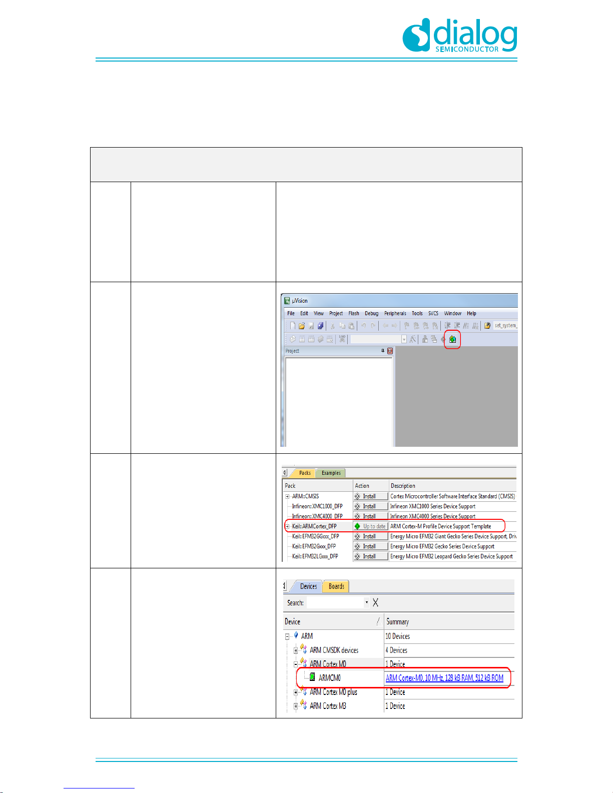
4.1 Keil
4.1.1
Download and install the Keil MDK-
ARM uVision IDE. Both uVision ver.
4.0 and ver. 5.0 are supported, but
version 5 is preferred.
Keil:
https://www.keil.com/download/product/
Keil MDK-ARM Version 5 –Installation:
http://www2.keil.com/mdk5/install
Starters Guide:
http://www.keil.com/uvision/ide_ov_starting.asp
4.1.2
For uVision Version 5 you have to
install the ARM Cortex M profile
package (see also
http://www.keil.com/dd2/Pack/)
4.1.3
You should see a list of packs as
shown on the right. If you do not
see this list, please click the
“Packs” menu item and select the
“Check for Updates” option to
download an updated list.
Click on the “Install” button to the
right of “Keil::ARMCortex_DFP”
package.
4.1.4
If the installation is successful, the
pack installer window should look
like this.
UM-B-034
DA14580/581/583 Bluetooth Smart development Kit –Pro
User manual
Revision 1.4
31-jan-2016
CFR0012 Rev 3
19 of 49
© 2016 Dialog Semiconductor
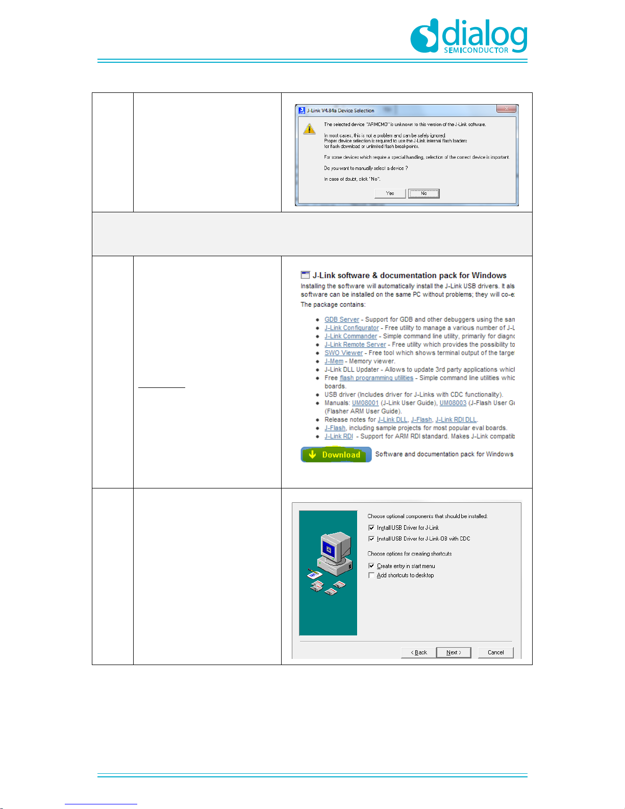
4.1.5
This screen may occur, is so:
Select ‘yes’ and in the next window
Select ‘M0’.
4.2 SEGGER Jlink driver
4.2.1
Download and install the Jlink
software & documentation pack for
Windows.
Please note that your SEGGER Jlink
serial number is required for
downloading. Use the number on the
sticker located on the backside of board.
http://www.segger.com/jlink-software.html
4.2.2
In order to for the USB controller to
be properly recognized by Windows
as a J-Link device, you have to
install the driver with the settings
shown in the figure on the right.
UM-B-034
DA14580/581/583 Bluetooth Smart development Kit –Pro
User manual
Revision 1.4
31-jan-2016
CFR0012 Rev 3
20 of 49
© 2016 Dialog Semiconductor
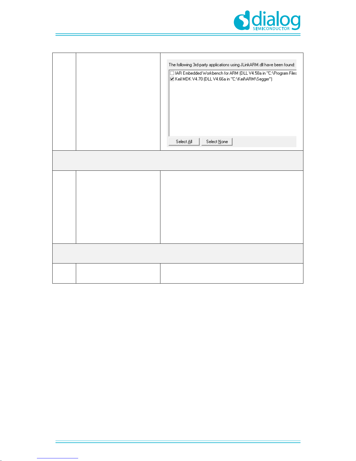
4.2.3
At the end of the installation, please
tick the IDE (Keil MDK Vxx) that
you are using.
4.3 FTDI driver
4.3.1
The Development Kit uses the
D2xx driver.
For Windows, this driver is part of
the Combined Driver Model (CDM)
driver.
(It is recommended that the latest driver
available from the FTDI page is used.)
Latency Timer: see Appendix F
USB Drivers:
http://www.ftdichip.com/Drivers/D2XX.htm
Installation Guide:
http://www.ftdichip.com/Support/Documents/InstallG
uides.htm
4.4 Tera Term
4.3.1
Download and install Tera Term on
your PC.
Tera Term:
http://en.sourceforge.jp/projects/ttssh2/releases/
Other manuals for DA14580
1
This manual suits for next models
2
Table of contents
Popular Accessories manuals by other brands

SMC Networks
SMC Networks PFM5 Series Operation manual

Endress+Hauser
Endress+Hauser Viomax CAS51D operating instructions

Baumer
Baumer UNDK 10P8914/KS35A operating instructions
 Specification sheet")
Panasonic
Panasonic MA2J111 (MA111) Specification sheet

Southwest Microwave
Southwest Microwave 300B Technical manual

Philio
Philio PAD02 quick start guide


Zip
Zip 42220 Sensor Tap AC Installation instructions & operating manual
 instruction manual")
AND
AND AD-4329-01 (BCD Output) instruction manual

Mr Safe
Mr Safe KB-333 user manual

cymatic audio
cymatic audio uTrack24 audiolan user manual

Contours
Contours Child Tray quick start guide

Barton
Barton 96078 Owner's manual and safety instructions