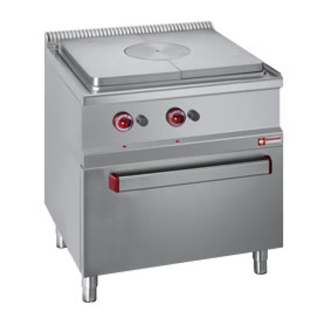
Diamond C4EA7-SP Quick start guide

Mod: C4EA7-SP
Production code: BC4EA77
03/2011

ISTRUZIONI PER L’INSTALLAZIONE, L’USO E LA MANUTENZIONE
INSTALLATION, USE AND MAINTENANCE INSTRUCTIONS
INSTRUCTIONS POUR L’INSTALLATION, L’EMPLOI ET L’ENTRETIEN
INSTALLATIONS-, BETRIEBS-UND WARTUNGSANLEITUNGEN
INSTRUCCIONES PARA LA INSTALACIÓN, EL USO Y EL MANTENIMIENTO
04/2010 - Rev.1 175004
PIANI DI COTTURA ELETTRICI
ELECTRIC COOKTOPS
TABLES DE CUISSON ELECTRIQUES
ELEKTRISCHE KOCHMULDEN
ENCIMERAS ELÉCTRICAS
I
GB
F
D
E
C4EA7-SP
C6EA7-SP

- 2 -
I
Avvertenze generali.............................................................................................................................. 3
1. Dati tecnici ........................................................................................................................................... 4
1.1 Piani di cottura elettrici ........................................................................................................................ 4
1.2 Caratteristiche tecniche ........................................................................................................................ 4
2. Istruzioni per l’installazione ................................................................................................................ 4
2.1 Targhetta dati piani di cottura elettrici ................................................................................................ 5
2.2 Leggi, norme e direttive tecniche ......................................................................................................... 5
2.3 Luogo d’installazione ........................................................................................................................... 5
2.4 Posizionamento .................................................................................................................................... 5
2.5 Montaggio apparecchiature top su base o supporto a sbalzo ............................................................... 5
3. Collegamento elettrico ......................................................................................................................... 6
3.1 Messa a terra ........................................................................................................................................ 6
3.2 Equipotenziale ..................................................................................................................................... 6
3.3 Cavo d’alimentazione .......................................................................................................................... 6
3.4 Consigli per l’installatore ..................................................................................................................... 6
3.5 Collegamento alle diverse reti elettriche di distribuzione .................................................................... 7
4. Sostituzione componenti più importanti .............................................................................................. 7
5. Istruzioni per l’utente ........................................................................................................................... 8
5.1 Piastre elettriche ................................................................................................................................... 8
5.2 Uso delle piastre elettriche ................................................................................................................... 9
6. Manutenzione e pulizia ........................................................................................................................ 9
SCHEMI DI INSTALLAZIONE ......................................................................................................... 42
SCHEMA ELETTRICO C4EA7-SP .................................................................................................... 43
SCHEMA ELETTRICO C6EA7-SP .................................................................................................... 44
CAPITOLO DESCRIZIONE PAGINA
INDICE
ITALIANO ......................................................................... pagina 2 - 9
ENGLISH ......................................................................... page 10 - 17
FRANÇAIS ........................................................................ page 18 - 25
DEUTSCH ......................................................................... Seite 26 - 33
ESPAÑOL ......................................................................... página 34 - 41

- 3 - I
- Leggere attentamente le avvertenze contenute nel presente libretto in quanto forniscono importanti
indicazioniriguardantilasicurezzadiinstallazione,d’usoedimanutenzione.
- Conservare con cura questo libretto per ogni ulteriore consultazione dei vari operatori.
- Dopo aver tolto l’imballaggio, assicurarsi dell’integrità dell’apparecchiatura e in caso di dubbio, non utilizzare
l’apparecchiatura e rivolgersi a personale professionalmente qualicato.
- Prima di collegare l’apparecchiatura, accertarsi che i dati riportati sulla targhetta siano corrispondenti a quelli
della rete di distribuzione elettrica.
- Questa apparecchiatura deve essere destinata solo all’uso per il quale è stata espressamente concepita, ogni
altro uso è da considerarsi improprio e quindi pericoloso.
- L’apparecchiatura deve essere utilizzata solo da persona addestrata all’uso della stessa.
- Per eventuale riparazione rivolgersi solamente ad un centro di assistenza tecnica autorizzato dal costruttore e
richiedere l’utilizzo di ricambi originali.
- Il mancato rispetto di quanto sopra, può compromettere la sicurezza dell’apparecchiatura.
- Non lavare l’apparecchiatura con getti d’acqua diretti e ad alta pressione.
- Non ostruire le aperture o feritoie di aspirazione o di smaltimento del calore.
- Lasicurezzaelettricaègarantitasoltantodaunefcaceimpiantodimessaaterra,comeprevistodalle
vigentinormedisicurezzaelettrica,èquindinecessariovericarequestofondamentalerequisito,ein
casodidubbio,richiedereilcontrolloaccuratodapartedipersonaleprofessionalmentequalicato.
- Ilcostruttorenonpuòessereconsideratoresponsabilepereventualidannicausatidallamancanzadi
messaaterradell’impianto.
- L’apparecchiatura deve essere inclusa in un sistema equipotenziale la cui efcienza deve essere vericata
secondo le norme in vigore.
- Tutte le apparecchiature sono fornite di cavo, della lunghezza di m. 2, con caratteristiche come specicato in Tab.
3.
- Il cavo essibile per l’allacciamento alla linea elettrica deve avere caratteristiche non inferiori al tipo con isolamento
in gomma H07RN-F.
In caso di inosservanza delle norme contenute nel presente manuale, sia da parte dell’utente che da parte del tecnico
addetto all’installazione, la Ditta declina ogni responsabilità ed ogni eventuale incidente o anomalia causato dalle
suddette inosservanze non potrà essere imputato alla stessa.
LA CASA COSTRUTTRICE DECLINA OGNI RESPONSABILITÀ PER LE POSSIBILI INESATTEZZE CONTENUTE NEL PRESENTE
OPUSCOLO, IMPUTABILI AD ERRORI DI TRASCRIZIONE O STAMPA. SI RISERVA INOLTRE IL DIRITTO DI APPORTARE AL
PRODOTTO QUELLE MODIFICHE CHE SI RITENGONO UTILI O NECESSARIE, SENZA PREGIUDICARE LE CARATTERISTI-
CHE ESSENZIALI.
AVVERTENZE GENERALI
PROVVEDIMENTINELCASOINCUIL’APPARECCHIATURANONVENGAUSATAPERMOLTOTEMPO.
Dopoaverpulitobenel’apparecchiatura,passareenergicamentesututtelesuperciinacciaiounpan-
noappenaimbevutodioliodivaselina,inmododastendereunveloprotettivo.

- 4 -
I
1.1 PIANI DI COTTURA ELETTRICI
1.2 CARATTERISTICHE TECNICHE
STRUTTURA Struttura portante in acciaio inox AISI 304, pannellatura e basamento in acciaio inox, montata su piedini
regolabili in altezza.
PIANO LAVORO in acciaio inox AISI 304 a tenuta stagna.
PIASTRE ELETTRICHE in ghisa a riscaldamento rapido, con protezione di sicurezza contro un eventuale surriscaldamento.
Ad ogni piastra è collegata una lampada spia verde che segnala il suo funzionamento.
COMMUTATORI ELETTRICI per comando piastre a 7 posizioni per una regolazione ottimale delle temperature delle stesse.
MANOPOLE COMANDI in materiale atermico.
L’installazione deve essere eseguita da persone qualicate secondo la normativa in vigore.
AVVERTENZE:
Nel caso in cui l’apparecchiatura venga installata contro una parete quest’ultima deve resistere ai valori di temperatura di
100°C e deve essere incombustibile.
Prima di togliere dal rivestimento la pellicola di protezione in plastica, eliminando gli eventuali residui adesivi con prodotto
adatto alla pulizia per l’acciaio inossidabile.
Installare l’apparecchio in posizione orizzontale, la corretta posizione si otterrà ruotando i piedini livellatori.
Qualora l’apparecchiatura venga installata singolarmente si consiglia di ssarla per rendere più sicura la sua stabilità.
2. ISTRUZIONI PER L’INSTALLAZIONE
1. DATI TECNICI
MODELLO DIMENSIONI
inmm
esterno
LxPxA/Amax
C4EA7-SP
C6EA7-SP
700x735x290/425
1100x735x290/425
POTENZAASSORBITA*
Ø145
1500W
2
3
Ø220
2600W
2
3
Ø220
2600W
-
-
totale
kW
8,2
12,3
PESO
NETTO
kg.
32
50
*TENSIONEDIALIMENTAZIONE:3N AC415V; 3 AC240V; 1N 240V 50/60Hz
N.B.:la potenza assorbita con 3N AC 380V ; 3 AC220 V; 1N 220V 50/60Hz è circa 16% inferiore.

- 5 - I
2.1 TARGHETTA DATI PIANI DI COTTURA ELETTRICI
La targhetta dei dati tecnici si trova:
a) sugli apparecchi con forno, sulla porta ed all’interno
b) sugli apparecchi senza forno, nell’armadio in basso a sinistra e all’interno
c) nei piani di cottura, sul retro ed all’interno.
V
KW
HZ
Matr. N°
Mod.
2.2 LEGGI, NORME E DIRETTIVE TECNICHE
Per l’installazione sono da osservare le seguenti norme:
- Prescrizioni vigenti antinfortunistiche e antincendio.
- La regolamentazione dell’ente distributore energia elettrica.
- Norme igieniche.
- Norme impianti elettrici.
2.3 LUOGO D’INSTALLAZIONE
- L’apparecchio deve essere installato in locali con sufciente areazione.
- Installare l’apparecchiatura secondo quanto previsto dalle norme di sicurezza.
2.4 POSIZIONAMENTO
- Le varie apparecchiature possono essere installate singolarmente o possono essere accoppiate ad altre apparecchiature della
stessa gamma
- Questa apparecchiatura non è idonea per l’incasso.
- La distanza dalla pareti laterali deve essere minimo di 10 cm., nel caso in cui la distanza fosse inferiore o il materiale delle
pareti o del pavimento fossero inammabili, è indispensabile l’applicazione di un isolante termico.
2.5 MONTAGGIO APPARECCHIATURE TOP SU BASE O SUPPORTO A SBALZO
Tutte le apparecchiature top sono munite di piedini rego-
labili in altezza (P):
- Quando l’apparecchiatura deve essere sistemata libera
su un tavolo o un piano, avvitare o svitare i piedini
(P) come indicato in figura sino a farla appoggiare
perfettamente, quindi stringere il controdado (D) in modo
da bloccare il piedino. Per impedirle di scivolare, inlare
nei buchi inferiori dei piedini i tappi in gomma (M).
- Quando l’apparecchiatura deve essere ssata su una
base o su un supporto a sbalzo, regolare i piedini (P)
sino a farla appoggiare perfettamente, stringere poi il
controdado (D) in modo da bloccare il piedino. Fissare
quindi da sotto mediante viti M5 (T) con relative rondelle
avvitandole ai piedini come indicato in gura.

- 6 -
I
3. COLLEGAMENTO ELETTRICO
L’allacciamento elettrico dev’essere eseguito nel rispetto delle norme CEI, solo da personale autorizzato e competente.
In primo luogo esaminare i dati riportati nella tabella dati tecnici del presente libretto, nella targhetta e nello schema elettrico.
L’allacciamento previsto è del tipo sso.
IMPORTANTE: A monte di ogni apparecchiatura è necessario prevedere un dispositivo di interruzione omnipolare della rete,
che abbia una distanza di contatti di almeno 3 mm., esempio:
- interruttore manuale di adatta portata, corredato di valvole fusibile
- interruttore automatico con relativi relè magnetotermici.
3.1 MESSA A TERRA
E’ indispensabile collegare a terra l’apparecchiatura.
A tale proposito è necessario collegare i morsetti, contraddistinti dai simboli ( ) posti sulla morsettiera arrivo linea, ad una
efcace terra, realizzata confermemente alle norme in vigore.
AVVERTENZE SPECIFICHE
La sicurezza elettrica di questa appartecchiatura è assicurata soltanto quando la stessa è correttamente collegata ad
un efcace impianto di messa a terra come previsto dalle vigenti norme di sicurezza elettrica; il costruttore declina,
ogni responsabilità qualora queste norme antinfortunistiche non vengano rispettate.
E’ necessario vericare questo fondamentale requisito di sicurezza e, in caso di dubbio, richiedere un controllo accurato
dell’impianto da parte di personale professionalmente qualicato.
Il costruttore non può essere considerato responsabile per eventuali danni causati dalla mancanza di messa a terra
dell’impianto.
ATTENZIONE: NON INTERROMPERE MAI IL CAVO DI TERRA (Giallo-verde).
3.2 EQUIPOTENZIALE
L’apparecchiatura deve essere inclusa in un sistema equipotenziale la cui efcienza deve essere vericata secondo le norme
in vigore. La vite contrassegnata con la targhetta «Equipotenziale» si trova vicina alla morsettiera sul basamento nei modelli
con forno e sul retro nei restanti modelli.
3.3 CAVO D’ALIMENTAZIONE
L’apparecchiatura viene consegnata predisposta per una delle seguenti tensioni:
3N AC 380...415 V; 3 AC 220...240 V; 1N AC 220...240 V 50/60 Hz.
Il cavo essibile per l’allacciamento alla linea elettrica deve essere di caratteristiche non inferiori al tipo con isolamento in
gomma H07RN-F. Il cavo deve essere introdotto attraverso il ferma cavo e ssato bene. Inoltre la tensione di alimentazione,
ad apparecchio funzionante, non deve discostarsi dal valore della tensione nominale ± 10%.
Per accedere alla morsettiera onde collegare l’apparecchiatura ad una rete d’alimentazione avente caratteristiche diverse da
quelle previste, o per sostituire il cavo d’alimentazione, occorre:
- smontare il pannello frontale (top o top + armadio) oppure
- smontare l’apposito pannello sul anco sinistro (cucina con forno)
- collegare il cavo d’alimentazione alla morsettiera secondo le necessità, seguendo le indicazioni riportate sull’apposita
etichetta collocata vicino alla morsettiera e nel presente libretto.
3.4 CONSIGLI PER L’INSTALLATORE
Mettere in funzione l’apparecchio secondo le istruzioni d’uso e spiegare il funzionamento all’utente utilizzando il libretto
istruzioni e illustrando eventuali modiche costruttive e/o funzionali. Lasciare il libretto istruzioni all’utente spiegando che
lo deve utilizzare per ogni ulteriore consultazione.

- 7 - I
3.5 COLLEGAMENTO ALLE DIVERSE RETI ELETTRICHE DI DISTRIBUZIONE
3NAC380...415V50/60Hz
PE (terra) giallo-verde
N (NP) azzurro
L3 (T) nero
L2 (S) nero
L1 (R) marrone
2NAC380...415V50/60Hz
PE (terra) giallo-verde
N (NP) azzurro
L2 (S) nero
L1 (R) marrone
3AC220...240V50/60Hz
PE (terra) giallo-verde
N (NP) azzurro
L3 (T) nero
L1 (R) marrone
1AC220...240V50/60Hz
PE (terra) giallo-verde
N (NP) azzurro
L1 (R) marrone Tab.2
123456
380...415V3N 50/60Hz
L1 L2 L3 N PE
L1 L2 N PE
380...415V2N 50/60Hz
220...240V3 50/60Hz
L1 N PE
220...240V 50/60Hz
L1 N PE
La targhetta dei tipi di collegamento elettrico si trova in prossimità della morsettiera.

- 8 -
I
CAVO D’ALIMENTAZIONE
MODELLO
TIPODITENSIONE
3N AC 380...415 V 50/60 Hz.
2N AC 380...415 V 50/60 Hz.
3 AC 220...240 V 50/60 Hz.
1N AC 220...240 V 50/60 Hz.
Mass.
A/f
N° cavi
mm2
Mass.
A/f
N° cavi
mm2
12,5
21,6
21,7
21,7
22,3
28,7
34,2
43,3
5 x 1,5
5 x 2,5
4 x 2,5
4 x 2,5
4 x 2,5
4 x 4
3 x 6
3 x 10
17,1
21,7
34,6
43,3
29,6
37,6
51,3
65,1
5 x 2,5
5 x 2,5
4 x 6
4 x 10
4 x 4
4 x 6
3 x 10
Tab.3
Le sostituzioni sottoriportate vanno eseguite solo da un “Centro Assistenza autorizzato”.
Prima di eseguire le sostituzioni dei componenti, si deve togliere tensione all’apparecchio tramite l’interruttore omnipolare.
A) Commutatore
- smontare il cruscotto
- svitare le viti che ssano il componente
- scollegare i li tenendo in considerazione lo schema elettrico
- sostituire il componente e riassemblare il tutto, utilizzando lo schema elettrico.
- rimontare il tutto seguendo l’ordine inverso di smontaggio.
4. SOSTITUZIONE COMPONENTI PIÙ IMPORTANTI
5.1 PIASTRE ELETTRICHE
La piastra elettrica viene trattata con una vernice di protezione, alla prima accensione si consiglia quindi prima di iniziare
le operazioni di cottura, di portare la manopola (Fig. 1) in posizione 3 lasciandola accesa per circa 5 minuti, quindi seguire
quanto indicato nelle avvertenze. Il tipo di stoviglia ottimale deve avere il fondo completamente piatto o leggermente bombato
verso l’interno in modo che durante il riscaldamento questo aderisca completamente alla supercie della piastra, ciò permette
un perfetto trasferimento di calore dalla piastra alla pentola. Si consiglia l’uso di recipienti di diamentro simile a quello della
piastra di cottura. Non appoggiare stoviglie di qualsiasi genere o coperchi sulle piastre.
Quando la piastra funziona a vuoto o vengono impiegati recipienti inadatti (es. di piccolo diametro o di scarsa qualità), un
dispositivo termostatico ne evita il surriscaldamento limitando la potenza.
Avvertenze: all’atto della prima accensione o comunque dopo un lungo tempo d’inoperosità è necessario, al ne di eliminare
l’eventuale umidità assorbita, provvedere al suo essicamento accendendo la piastra per 30 minuti nella posizione n° 1 del
commutatore.
- Asciugare il fondo della pentola prima di posarlo sulla piastra.
- Accendere la piastra solo dopo aver appoggiato la pentola.
5. ISTRUZIONI PER L’UTENTE
C4EA7-SP C6EA7-SP

- 9 - I
5.2 USO DELLE PIASTRE ELETTRICHE
La manopola di comando (Fig. 1) suddivisa in sette posizioni comanda la piastra elettrica e ne regola la potenza.
Per accendere la piastra ruotare la manopola dalla posizione “0” portandola nella posizione desiderata (vedere tabella sotto
riporatata), automaticamente si accenderà la spia luminosa verde che segnala il suo funzionamento.
PIASTRA RAPIDA
Per spegnere la piastra è sufciente ruotare la manopola in qualsiasi direzione portando lo “0” in corrispondenza dell’indice.
POS.
6
5
4
3
2
1
0
IMPIEGO
COTTURA
MANTENIMENTO
SPENTO
{ }
{ }
Ø220mm
W
2600
1750
1300
450
340
240
0
Ø145mm
W
1500
750
500
250
165
135
0
%
100
50
33
17
11
9
0
%
100
67
50
17
13
9
0
Tab.4
Fig.1
- Pulire giornalmente la parti in acciaio inox con acqua tiepida saponata, quindi risciacquare abbondantemente ed asciugare
con cura.
- Evitare nel modo più assoluto di pulire l’acciaio inox con paglietta, spazzola o raschietti di acciaio comune in quanto possono
depositare particelle ferrose che ossidandosi provocano punti di ruggine. Può essere eventualmente adoperata lana di acciaio
inossidabile passata nel senso della satinatura.
- Qualora l’apparecchiatura non venga utilizzata per lunghi periodi, passare energicamente su tutte le superci in acciaio un
panno leggermente imbevuto di olio di vaselina, in modo da stendere un velo protettivo. Arieggiare periodicamente i locali.
PIANO DI COTTURA - PIASTRE ELETTRICHE
Si raccomanda di tenere sempre pulite ed asciutte le piastre di cottura, rimuovendo le untuosità e le incrostazioni usando
anche l’apposito detergente.
Per proteggerle a lungo si consiglia, dopo la pulizia, di passarle con uno stronaccio umido, asciugarle (mettendole eventual-
mente in funzione) e ricoprirle di un leggero velo d’olio di vaselina.
PARTI IN ACCIAIO INOSSIDABILE
I particolari in acciaio inox devono essere puliti con acqua saponata e poi asciugati con un panno morbido.
La lucentezza viene mantenuta mediante ripassatura periodica, con POLISH liquido, (un prodotto facilmente reperibile).
6. MANUTENZIONE E PULIZIA

- 10 -
GB
CHAPTER DESCRIPTION PAGE
CONTENTS
General notices ..................................................................................................................................... 11
1. Technical data ...................................................................................................................................... 12
1.1 Electric hobs......................................................................................................................................... 12
1.2 Technical characteristics ...................................................................................................................... 12
2. Installation instructions ....................................................................................................................... 12
2.1 Information about electric hobs ........................................................................................................... 13
2.2 Laws, regulations and technical directives ......................................................................................... 13
2.3 Installation place .................................................................................................................................. 13
2.4 Positioning ........................................................................................................................................... 13
2.5 Mounting the top units on a base or an extending support .................................................................. 13
3. Electrical connection ............................................................................................................................ 14
3.1 Earthing ................................................................................................................................................ 14
3.2 Equipotential ........................................................................................................................................ 14
3.3 Power supply cable .............................................................................................................................. 14
3.4 Advice to tters .................................................................................................................................... 14
3.5 Connections to various main power supplies ....................................................................................... 15
4. Replacing important components ........................................................................................................ 16
5. Instructions to users ............................................................................................................................. 16
5.1 Cooking plates ..................................................................................................................................... 16
5.2 Using the cooking plates ...................................................................................................................... 17
6. Maintenance and cleaning .................................................................................................................... 17
INSTALLATION DIAGRAMS ........................................................................................................... 42
ELECTRIC DIAGRAMS C4EA7-SP ................................................................................................. 43
ELECTRIC DIAGRAMS C6EA7-SP ................................................................................................. 44

- 11 - GB
- Carefullyreadtheinstructionscontainedinthepresentbookletastheysupplyimportantinformation
relatingtosafeinstallation,useandmaintenance.
- Keep this booklet with care, for any further consultation by the various operators.
- Having removed the packing, make sure the unit is in good order and in case of doubt, do not use the unit, but
call on skilled personnel.
- Before connecting the unit, make sure the data appearing on the serial plate correspond to those of the main
electric supply.
- The unit must be used only by a person trained for its operation.
- Before performing cleaning or servicing operations, disconnect the unit from the electric supply.
- Shut off the unit in case of fault or bad functioning. For any repairs, please call exclusively an authorised technical
service centre, and ask for original spare parts only. Non compliance with the above may compromise the unit’s
safety.
- This unit must only be used for the purpose it was expressly built for.
- Do not wash the unit with direct or high-pressure water jets.
- Do not obstruct openings or draft grids or heat vents.
- Electricalsafetyisguaranteedonlybyanefcientearthingsystem,asenvisagedbytheelectricalsafety
regulationinforce:itisthereforenecessarytoverifythisessentialrequisiteand,incaseofdoubt,
requestanaccuratecheck-upbyprofessionallyqualiedpersonnel.
- TheManufacturercannotbedeemedresponsibleforanydamagescausedbythelackofearthinginthe
system.
- The unit must be included in an equipotential system whose efciency should be tested in compliance with the
law in force.
- All units are supplied with a 200cm long cable having the characteristics shown in Tab. 3.
- The hook-up wire for the power supply connection should not have characteristics below the type with rubber
insulation H07RN-F
GENERAL NOTICES
In the event of the user or the installation technician failing to observe the instructions given in this manual, the Firm
disclaims all responsibility thereof and cannot be held liable for any accidents or trouble caused by such non-observance.
THE MANUFACTURER DISCLAIMS ALL RESPONSIBILITY FOR ANY INACCURACIES IN THIS BOOKLET THAT MAY BE
DUE TO TYPING OR PRINTING MISTAKES. THE MANUFACTURER, MOREOVER, RESERVES THE RIGHT TO MAKE THE
MODIFICATIONS TO THE PRODUCT IT CONSIDERS USEFUL OR NECESSARY, WITHOUT AFFECTING ITS BASIC FEATURES.
MEASURESTOBETAKENWHENTHEEQUIPMENTISNOTUSEDFORALONGTIME.
Aftercleaningtheequipmentwell,wipethoroughlyallthesteelsurfaceswithaclothslightlysoakedin
Vaselineoilandapplyathinprotectivecoat.

- 12 -
GB
1.1 ELECTRIC HOBS
1.2 TECHNICAL CHARACTERISTICS
STRUCTURE Stainless steel frame AISI 304, stainless steel panels and base mounted on height-adjustable feet.
TOP in stainless steel AISI 304 seal tight.
COOKING PLATES made of cast iron and with fast heat-up system; tted with a safety protection against any overheating.
Each plate is connected to a green indicator light signalling its activation.
ELECTRIC SWITCHES controlling the elements with 7 positions, for an optimum element temperature adjustment.
CONTROL KNOBS made of insulated material.
Installation must be performed by qualied technicians according to the law in force.
WARNINGS:
Should the unit be installed against a wall, the latter must be heat-resistant to temperatures of 100°C and must be reproof.
Before proceeding with the installation, remove the protective plastic lm from the relevant parts, eliminating any adhesive
residues with an appropriate cleaning product suitable for stainless steel.
Install the unit in a horizontal position; its correct levelling will be achieved by rotating the adjustable feet.
If the unit is installed by itself, it is advisable to fasten it to make its stability safer.
2.1 INFORMATION ABOUT ELECTRIC HOBS
1. TECHNICAL DATA
2. INSTALLATION INSTRUCTIONS
MODEL DIMENSIONS
inmm
external
WxDxH/Hmax
ABSORBEDPOWER*
Ø145
1500W
Ø220
2600W
Ø220
2600W
total
kW
NET
WEIGHT
kg.
*VOLTAGESUPPLY:3N AC415V; 3 AC240V; 1N 240V 50/60Hz
N.B.:power absorbed with 3N AC 380V ; 3 AC220 V; 1N 220V 50/60Hz is approx. 16% less.
700x735x290/425
1100x735x290/425
2
3
2
3
-
-
8,2
12,3
32
50
C4EA7-SP
C6EA7-SP

- 13 - GB
The serial plate is located as follows:
a) for units with oven, on the door and inside.
b) for units without oven, on the lower left side of cabinet and inside.
c) for hobs, at back and inside.
V
KW
HZ
Matr. N°
Mod.
2.2 LAWS, REGULATIONS AND TECHNICAL DIRECTIVES
The following indications should be observed during installation:
- Accident and re regulations in force
- The regulations of the electric power supply company.
- Hygienic regulations.
- The rules for electrical systems.
2.3 INSTALLATION PLACE
- The unit should be installed in adequately ventilated places.
- Install the unit in compliance with the safety regulations.
2.4 POSITIONING
- The various units may be installed individually or together with other units of our range.
- This unit is not suitable for encasing.
- The distance between side walls must be a minimum of 10cm; should the distance be less or the wall or oor mate-
rial be ammable, it is essential to use a thermal insulator.
2.5 MOUNTING THE TOP UNITS ON A BASE OR AN EXTENDING SUPPORT
All Top units are supplied with height-adjustable feet (P):
- When the unit is to be placed free on a table or a surface,
tighten or loosen the feet (P) as shown in the illustration
till it is perfectly steady, then tighten the locknut (D) so
that the foot is blocked. To prevent slipping, insert the
rubber plugs (M) into the feet’s lower holes.
- When the unit is to be xed to a base or an extending
support, adjust the feet (P) till it is perfectly steady,
then tighten the locknut (D) so that the foot is blocked.
Subsequently fasten from beneath by way of M5 screws
(T) and respective washers, screwing them into the feet
as shown in the illustration

- 14 -
GB
Electrical connection should be performed in compliance with the IEC regulations, only by authorised and competent person-
nel. In the rst instance, examine the data shown on the technical data table of this manual, on the label and on the electrical
diagram. The envisaged connection is of the xed type.
IMPORTANT: Ahead of each unit it is necessary to install an omnipolar main breaker, having a spacing among contacts of
at least 3mm; example:
- manual breaker of appropriate capacity, complete with fuse valves
- automatic breaker with respective magnetothermal relays.
3.1 EARTHING
It is essential to earth the unit.
To this purpose, it is necessary to connect to an efcient earthing system the terminals marked with the symbols ( )
placed on the line-receiving terminal box. The earthing system should comply with the law in force.
SPECIFIC WARNINGS
The electrical safety of this unit is assured only when it is correctly connected to an efcient earthing system as stated
in the electrical safety regulations in force; the Manufacturer declines any responsibility for the non-compliance with
these safety regulations.
It is necessary to verify this fundamental safety requisite and, in case of doubt, ask for an accurate testing of the system by
professionally qualied personnel.
The Manufacturer cannot be deemed responsible for any damages caused by the lack of unit earthing.
ATTENTION: NEVER INTERRUPT THE EARTH WIRE (Yellow-Green).
3.2 EQUIPOTENTIAL
The unit should be included within an equipotential system whose efciency must be tested according to the law in force.
The screw marked with the label “Equipotential” is located near the terminal box on the base for models with oven, and at
the back for the remaining models.
3.3 POWER SUPPLY CABLE
The unit is supplied tted for the following voltages:
3N AC 380...415V; 3 AC 220...240V; 1N AC 220...240V 50/60 Hz.
The exible cable for power supply connection should not have characteristics lower than the rubber insulation type
H07RN-F. The cable should be inserted through the cable clamp and rmly fastened. Furthermore, the supply voltage with
the unit functioning should not go outside the value of the nominal tension ±10%.
To have access to the terminal box in order to connect the unit to a supply network having different characteristics from those
provided for, or to replace the supply cable, you need to:
- remove the front panel (top or top + cabinet) or
- remove the appropriate panel on the left side (cooker with electric oven)
- connect the cable to the terminal box according to need, and following the instructions shown on the provided sticker near
the terminal bord and on the present booklet.
3.4 ADVICE TO FITTERS
Activate the unit according to the use instructions, and explain its operation to the user by consulting the instruction booklet,
illustrating also any manufacturing and/or functional modications.
Leave the instruction booklet with the user, advising that he/she should refer to it for any future consultation.
3. ELECTRICAL CONNECTION

- 15 - GB
3.5 CONNECTIONS TO VARIOUS MAIN POWER SUPPLIES
3NAC380...415V50/60Hz
PE (earth) yellow-green
N (NP) blue
L3 (T) black
L2 (S) black
L1 (R) brown
2NAC380...415V50/60Hz
PE (earth) yellow-green
N (NP) blue
L2 (S) black
L1 (R) brown
3AC220...240V50/60Hz
PE (earth) yellow-green
N (NP) blue
L3 (T) black
L1 (R) brown
1AC220...240V50/60Hz
PE (earth) yellow-green
N (NP) blue
L1 (R) brown
Tab.2
123456
380...415V3N 50/60Hz
L1 L2 L3 N PE
L1 L2 N PE
380...415V2N 50/60Hz
220...240V3 50/60Hz
L1 N PE
220...240V 50/60Hz
L1 N PE
The electrical connection plate is placed near the terminal board.

- 16 -
GB
POWER SUPPLY CABLE
MODEL
SUPPLYVOLTAGETYPE
Tab.3
The replacements described below should only be performed by an “Authorised Service Centre”.
Before replacing any component, you should shut off power supply from the unit by using the omnipolar switch.
A) Switch
- remove the dashguard
- undo the screws fastening the component
- disconnect the wires following the electrical diagram
- replace the component and re-assemble everything back, using the electrical diagram
- mount back each part following the reverse sequence.
4. REPLACING IMPORTANT COMPONENTS
5. INSTRUCTIONS TO USERS
5.1 COOKING PLATES
The cooking plate is treated with a protection paint. On rst using it, we therefore suggest to set the knob (Fig. 1) on position
3, leaving it on for approx. 5 minutes. Optimum crockery should have a fully at or slightly cambered base, in order for it
to adhere completely to the element surface during heating: this allows a perfect heat transfer from the element to the pan.
We recommend the use of pans having a diameter equal to that of the cooking element. Do not rest kitchenware or lids of
any kind on the elements. When the element is functioning with no pan on its top or unsuitable pans are used (e.g., small in
diamater or poor in quality), a thermostat device prevents overheating by limiting its power.
Warning: on rst operating it or at any rate after a long period of inactivity, so as to eliminate any humidity absorbed, you
should dry up the element by turning it on for 30 minutes with the switch on position No. 1.
- Wipe dry the pan bottom before placing it on the cooking plate.
- Turn on the cooking plate only after you have placed the pan on its top.
3N AC 380...415 V 50/60 Hz.
2N AC 380...415 V 50/60 Hz.
3 AC 220...240 V 50/60 Hz.
1N AC 220...240 V 50/60 Hz.
Mass.
A/f
N° cavi
mm2
Mass.
A/f
N° cavi
mm2
12,5
21,6
21,7
21,7
22,3
28,7
34,2
43,3
5 x 1,5
5 x 2,5
4 x 2,5
4 x 2,5
4 x 2,5
4 x 4
3 x 6
3 x 10
17,1
21,7
34,6
43,3
29,6
37,6
51,3
65,1
5 x 2,5
5 x 2,5
4 x 6
4 x 10
4 x 4
4 x 6
3 x 10
C4EA7-SP C6EA7-SP

- 17 - GB
5.2 USING THE COOKING PLATES
The control knob (Fig. 1) subdivided into seven positions, controls the surface element and sets its power.
To switch on the element, turn the knob from position “0” to the desired position (see table below): a green indicator light
will automatically come on, signalling its activation.
FAST ELEMENT
To switch off the element, it is sufcient to turn the knob in any direction, bringing the “0” to the index - indicator.
POS.
6
5
4
3
2
1
0
IMPIEGO
COTTURA
MANTENIMENTO
SPENTO
{ }
{ }
Ø220mm
W
2600
1750
1300
450
340
240
0
Ø145mm
W
1500
750
500
250
165
135
0
%
100
50
33
17
11
9
0
%
100
67
50
17
13
9
0Fig.1
- Clean the stainless steel parts daily with soapy lukewarm water, then rinse well and dry throughly.
- Absolutely avoid to clean the stainless steel with common steel-wool, or common steel brushes and scrapers, as they
may discard ferrous particles which, on depositing, cause rust spots. You may, if you like, use stainless steel-wool
passed on following the butter-nish direction.
- Should the unit remain unused for long periods, heavily rub all the steel surfaces with a cloth slightly wetted with vaseline
oil, in order to cover them with a protective lm. Periodically ventilate the premises.
COOKTOP - ELECTRIC COOKING PLATES
We recommend to keep the cooking plates always clean and dry, removing any grease and incrustations through the use also
of appropriate detergent.
To protect them lastingly, we suggest to wipe them with a moist cloth after cleaning, then dry them (possibly by switching
them on) and cover them with a thin lm of vaseline oil.
STAINLESS STEEL PARTS
The stainless steel parts must be cleaned with soapy water and then dried with a soft cloth. The bright polish is kept by perio-
dical wiping with liquid (POLISH), a product easily available.
6. MAINTENANCE AND CLEANING

- 18 -
F
CHAPITRE DESCRIPTION PAGE
SOMMAIRE
Regles generales ................................................................................................................................... 19
1. Donnees techniques ............................................................................................................................. 20
1.1 Tables de cuisson electrique ................................................................................................................. 20
1.2 Caracteristiques techniques .................................................................................................................. 20
2. Instructions pour l’installation ............................................................................................................. 20
2.1 Plaquette d’identication des tables de cuisson electriques .............................................................. 21
2.2 Legislation a respecter ........................................................................................................................ 21
2.3 Lieu d’installation ................................................................................................................................ 21
2.4 Mise en place ....................................................................................................................................... 21
2.5 Montage de l’appareil sur une base ou un support ............................................................................. 21
3. BRanchement electrique ...................................................................................................................... 22
3.1 Mise a la terre ....................................................................................................................................... 22
3.2 Systeme equipotentiel ......................................................................................................................... 22
3.3 Cordon d’alimentation ......................................................................................................................... 22
3.4 Informations de l’usager ...................................................................................................................... 22
3.5 Branchements au differents reseaux electriques de distribution .......................................................... 23
4. Changement des composants plus importants ..................................................................................... 24
5. Informations de l’usager ...................................................................................................................... 24
5.1 Plaques electriques ............................................................................................................................... 24
5.2 Utilisation des plaques electriques ....................................................................................................... 25
6. Entretien et nettoyage .......................................................................................................................... 25
SCHEMAS D’INSTALLATION ......................................................................................................... 42
SCHEMA ELECTRIQUE C4EA7-SP ................................................................................................. 43
SCHEMA ELECTRIQUE C6EA7-SP ................................................................................................. 44

- 19 - F
- Lisezattentivementlesinstructionscontenuesdanscettenoticecarellesfournissentd’importantes
indicationsconcernantlasécuritéd’installation,d’emploietd’entretien.
- Rangez soigneusement cette notice dans un endroit accessible et adapté à de futures consultations.
- Après avoir déballé l’appareil, contrôlez-en l’intégrité. En cas de doute ne l’utilisez pas et adressez-vous à un
personnel qualié.
- Avant de brancher l’appareil, assurez-vous que les informations reportées sur la plaquette signalétique
correspondent à celles du réseau de distribution électrique.
- Cet appareil n’est destiné qu’à l’usage pour lequel il a été expressément conçu. Tout autre usage est considéré
impropre et donc dangereux.
- L’appareil ne doit être utilisé que pas une personne formée à son usage et ayant pris connaissance du contenu
de cette notice.
- Pour les réparations adressez-vous seulement à un centre de service après-vente agréé par le Fabricant et
exigez des pièces de rechange d’origine.
- Le non respect de ces indications peut compromettre la sécurité de l’appareil.
- Ne dirigez jamais de jets d’eau à haute pression sur l’appareil pour le laver.
- N’obstruez jamais les ouvertures ou les fentes d’aspiration ou d’évacuation de la chaleur.
- Lasécuritéélectriquen’estgarantiequeparunemiseàlaterreefcace,conformémentàlalégislation
envigueurenmatièredesécuritéélectrique.Encasdedoute,faitescontrôlervotreinstallationparun
électricienqualié.
- LeFabricantdéclinetoute responsabilitéencas dedégâtscausés àdespersonnes ouàdes biens
provoquésparl’absencedemiseàlaterredel’appareil.
- L’appareil doit être inclus dans un système équipotentiel dont l’efcacité devra être vérié conformément à la
législation en vigueur.
- Tous les appareils sont livrés avec un cordon d’alimentation de 2 m, avec les characteristiques indiquées dans
le Tableau 3.
- Les caractéristiques du câble exible de branchement à la ligne électrique doivent être au moins égales au câble
avec isolation en caoutchouc H07RN - F.
En cas de non respect des instructions contenues dans ce manuel, aussi bien de la part de l’usager que de l’installateur,
le Fabricant décline toute responsabilité en cas de dégâts à des personnes ou à des biens provoqués par ce non respect.
LE FABRICANT DECLINE TOUTE RESPONSABILITE SUR LES CONSEQUENCES IMPUTABLES A D’EVENTUELLES INEXAC-
TITUDES DUES A DES ERREURS DE TRANSCRIPTION OU D’IMPRESSION. LE FABRICANT SE RESERVE AUSSI LE DROIT
D’APPORTER TOUTES LES MODIFICATIONS QU’IL RETIENDRA UTILES OU NECESSAIRES SUR LES PRODUITS SANS EN
MODIFIER, CEPENDANT, LES CARACTERISTIQUES PRINCIPALES.
REGLES GENERALES
MESURESÀPRENDREENPRÉVISIOND’UNELONGUEPÉRIODED’INACTIVITÉ
Nettoyeràfondtoutl’appareiletpasserunchiffonàpeineimbibéd’huiledevaselinesurtouteslessur-
facesenacierdefaçonàappliquerunvoileprotecteur.
This manual suits for next models
2
Table of contents
Languages:
Other Diamond Cooktop manuals