Diamond PSB-41M/2V User manual

Mod: PSB-41M/2V
Production code: SP401
06/2022

Instruction Manual
PSB-41M/2V (SP401)
PSB-61M/2V (SP601)
SPIRAL MIXER
Edition 1/07/2015
Revision 10/10/2016

2
INDEX
0.0 Preface...............................................................................................................................................................4
1.0 Manual purpose and use ..................................................................................................................................4
1.1 EC data marking.................................................................................................................................................4
2.0 Warnings, description and security criteria.......................................................................................................5
2.1 Warnings............................................................................................................................................................5
2.1 Machine general description.............................................................................................................................5
2.1.1 Work environment .........................................................................................................................................5
2.1.2 Disposal ..........................................................................................................................................................6
3.0 Unacceptable conditions of use ........................................................................................................................6
3.1 Cleaning .............................................................................................................................................................6
3.2 Reference norms ...............................................................................................................................................6
3.3 Operators...........................................................................................................................................................7
4.0 Use of the machine............................................................................................................................................7
4.1 Technical data....................................................................................................................................................7
4.2 Trasport and handling .......................................................................................................................................8
4.3 Installation and commissioning.........................................................................................................................9
4.3.1 Installation......................................................................................................................................................9
4.3.2 Correct functioning control ..........................................................................................................................10
4.4 Normal and safety stop ...................................................................................................................................10
4.4.1 Manual mode stop .......................................................................................................................................10
4.4.2 Automatic mode stop ...................................................................................................................................11
4.4.3 Safety stop ....................................................................................................................................................11
4.4.3.1 Safety stop Europe Model .........................................................................................................................11
4.4.3.2 Safety stop Brazil Model............................................................................................................................12

3
4.5 Processing cycles description, manual and automatic ...................................................................................12
4.5.1 Machine charging .........................................................................................................................................13
4.5.2 Processing cycle execution ...........................................................................................................................13
4.5.2.1 Manual mode cycle ...................................................................................................................................13
4.5.2.2 Automatic mode cycle...............................................................................................................................14
4.5.3 Machine discharge .......................................................................................................................................14
5.0 Maintenance....................................................................................................................................................14
5.1 Ordinary maintenance.....................................................................................................................................15
5.1.1 Cleaning ........................................................................................................................................................15
5.1.2 Command functioning and safety systems control......................................................................................15
5.1.3 Belt tension control .....................................................................................................................................16
5.1.3.1.1 Spiral transmission maintenance SP401,SP601,SP801 models .............................................................16
5.1.3.1.2 Spiral transmission maintenance SP801 Gold model............................................................................18
5.1.3.2.1 Bowl transmission maintenance SP401,SP601,SP801 models ..............................................................19
5.1.3.2.2 Bowl transmission maintenance SP801 Gold model.............................................................................19
5.1.4 Adjustable holders' greasing .......................................................................................................................20
5.1.4.1 Adjustable holders for SP401, SP601,SP801 models................................................................................20
5.1.4.1 Adjustable holders for SP801 Gold model................................................................................................21
5.2 Programmed maintenance..............................................................................................................................22
5.2.1 Spiral holder bearings replacement ............................................................................................................22
5.2.2.1 Bowl holder bearings SP401, SP601, SP801 models.................................................................................23
6.0 Attachments ....................................................................................................................................................25
6.1 Main groupsets................................................................................................................................................25

4
0.0 Preface
1.0 Manual purpose and use
The information contained in the manual is addressed to:
-personnel responsible of the machine repair and maintenance
-personnel responsible of the machine installation
-personnel responsible of the machine use
-personnel responsible of the machine dismantling
The user must keep the manual, avoiding to damage it and making it easily accessible and searchable.
The manual is divided into four chapters: a preface and four chapters concerning the machine’s description,
security, use and maintenance.
-Preface:Manufacturer company indication and machine’s plate data definition, manual
purpose.
-Chapter 2: Warnings, general description.
-Chapter 3: Security reference norms and general information about the typology of the
machine in question.
-Chapter 4: Machine technical and functional data, transport, installation, functioning, use.
-Chapter 5: Ordinary and programmed maintenance instructions, technical schemes and
machine functional group sets assembly drawings.
For further information please contact the manufacturer company or an authorized commercial agent directly,
giving the plate data reported on the machine as reference of the machine itself.
1.1 EC data marking
CE
MODEL
__________
SERIAL NUMBER
__________
DATE OF MANUF.
__________
VOLTAGE
__________
FREQUENCY
__________
PHASE
__________
AMPS
__________
The contents of this manual are in compliance with the machine directives ECC 89/392, Attachment I,
Paragraph 1.7.4

5
2.0 Warnings, description and security criteria
2.1 Warnings
The machine efficiency conditions keeping depends on the correct use and maintenance respect as described
in this manual.
The manufacturer request that:
-Every argument treated in the manual must be read and clearly understood before using the machine.
-The machine must not be tampered, altered or modified even partially, in particular safeguards can’t be
removed.
- The machine can’t be used in conditions or for uses not specified in this manual. The manufacturer will be
relieved of any responsibility about breaks, malfunction or accidents caused by the non-observance of this
rules.
The EC marking is secured at the center of head’s rear side.
2.1 Machine general description
The machine was designed and built for professional use in the food industry.
The purpose of the mixer is to make a well blended dough for both bakery and confectionery.
The following are the technical data that define the use of the machine together with the functions available.
2.1.1 Work environment
Operating parameters for a good machine performance:
-Temperature: +5/+40° C, with the average temperature not exceeding 35°C over a period of 24
hours.
-Relative humidity:from 30% to 95% in the absence of condensation.
The confinement environment of the machine must provide a space suitable for carrying out the cleaning and
maintenance of the machine itself.
The noise level of the machine never exceeds 70dB, whatever the operating condition.
2.1.2 Disposal
In the eventuality that the machine has to be scraped, its components must be selected on their composition
and treated as industrial waste, according to the rules in force.

6
No component of the machine is classified as a toxic or harmful product.
3.0 Unacceptable conditions of use
It is forbidden to use the machine in the following conditions:
-Bigger loads than allowed.
- Security system tampering.
-Using equipment not supplied with the machine, not suitable for food contact or which can damage
the bowl surface.
-Using the machine in a not suitable environment.
3.1 Cleaning
Since the machine is used for food processing, cleaning must be complete and executed on a daily basis.
For the removal of any incrustations it must be used only water together with non-abrasive sponges and
plastic spatulas.
The machine surrounding area must be clean and the machine must be moved regularly to clean the surface
occupied by the machine itself.
When the machine is moved the wheels brake must be unlocked (Brazil model) or the leveling feet must be
lifted completely (Europe model) and the power outlet must be disconnected.
3.2 Reference norms
The machine described in this manual complies with the 89/392 / ECC directive, its amendments and the
following regulations:
-UNI EN 292-1, UNI EN292-2. Basic notions for machine safety and general design principles.
-UNI EN 294 Safety distances.
-UNI EN 349 Minimal distance to avoid crushing body parts.
-EN 60204-1 Electrotechnical aspects.
-EN 453 Food processing machines -Dough mixers
3.3 Operators
The machine has been designed and built for professional use. Hence:

7
-The operator must know the deployed functions available on the control panel, the installed safety
systems and must verify regularly their efficiency. He must know all possible work cycles and the
quantities of product to be used. He must also clean the machine everyday.
-The maintenance technician (see chapter 5), must verify the control panel commands functionality,
the safety systems and he must check the driving belts condition.
-The programmed maintenance and repair technician (see chapter 5) must be authorised by the
manufacturer before performing any operations on the machine while the machine is under warranty.
Refer to the maintenance chapter (chapter 5).
4.0 Use of the machine
The use of the machine is summarized in Table 4.1 which defines the maximum product quantities that can be
processed according to the machine model.
The following paragraphs describe the stages of transposition, installation, commissioning.
4.1 Technical data
The maximum amount of dough for each machine model was estimated considering 60% of water compared
to the amount of flour.
Table 4.1
Model
Dough
specifications
Bowl
specifications
Machine footprint & Bowl
edge from ground
Motor
power Speed
Maximum capacity
Flour
Water
Volume
Diameter
Height
L
ength
Weidth
Height
Height bowl edge
Weight
1st / 2nd Speed
Spiral
1st / 2nd Speed
Bowl
1st / 2nd Speed
kg
kg
L
L
cm
cm
cm
cm
cm
cm
kg
kw
rpm
rpm
SP401 40 25 15 68 53 32 101
56 125 70 250 1.5/3
112
224
12
24
SP601 60 37.5
22.5
92 58 36 107
62 125 74 270 1.5/3
112
224
12
24
SP801 80 50 30 132 70 37 118
74 128 75 310 3/5.2
112
224
12
24
SP801 Gold 80 50 30 132 70 37 123
73 145 81 512 3/5.2
107
214
12
24
4.2 Transport and handling
The machine lifting for handling and transporting must be done with the help of suitable means and
equipment, avoiding oscillations during the various phases.

8
The machine weight is decentralised so the forklifts are positioned as shown in Figures 1 and 2. To handle the
packaging refer to the precautions indicated on the sheet placed outside of the packaging and in Figure 1, Pos.
5 (Pos. = Position).
Fig. 1 Packaging Lifting
The machine is transported on a wooden pallet Pos. 1, blocked with a crossbar on C Pos. 2 through two
threaded rods, Pos. 3.
Lifting by means of a forklift truck involves inserting the forks in the Pos. 4.
Check the suitability of the equipment before lifting.
The packaging material used Pos.1 and 2 is an industrial waste while the remainder can be recycled or
disposed as urban waste.
Fig. 2 Machine transport.
Remove the Pos.2 locking device, insert the
Pos.4 forks as shown in the figure 2 and carefully
lift the machine while maintaining an horizontal
position, without jerk or oscillations.
4
1

9
1
1
2
2
1
1
3
3
4
4
4.3 Installation and commissioning
Preparatory stages for the machine installation and commissioning:
-Identify an area suitable for food-processing that is completely accessible for cleaning in which collocate
the machine.
-It is not necessary to provide floor anchors but the floor must be well leveled because SP401,601 and
SP801 models do not have leveling feet, whereas the SP801 Gold model comes with frontal legs.
-Check that the power line is properly connected by means of a suitable outlet.
-Check that any command and removable safety protections work properly.
4.3.1 Installation
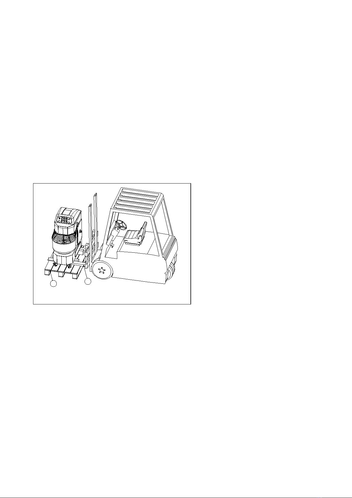
Once the machine has been transported to the chosen location, the installation is carried out following the
stages outlined below (see figs.3/4):
a) For SP401, SP601 and SP801 models, lock
the wheels by pressing on the lever with the
foot Pos.1 Fig.3a, until the lever remains
locked. For the SP801 Gold model the
positioning of the machine is done by
adjusting the front legs Pos.51 fig.3b through
the hand wheel Pos.53 and subsequently
blocking by tightening the nut, Pos.52.
b) Connect the machine to the power outlet,
turn the knob on Pos.3 and check that the ON
lights up, Pos. 4, Fig.4/5.
c) Check that the bowl protection is turned
down, Pos. 4, Figg.3a/3b.
d) Push on Start button, Pos. 5 Fig. 4/5
If the tank turns clockwise, ie opposite to the
one indicated by the arrow on the side of the
tank, the phases on the engine are incorrect,
then swap two of the three phases in the
socket.
The control panel Pos.2, figs.3/4/5 is
composed of:
1
51
53
52
4
2
3
2
4
51
54
53
51
53
7
Fig.3b : SP801- Gold Installation
Fig.3a : SP401/601-SP801 Installation

10
3. Emergency STOP button
4. Light-signalling connection to the main
5. START button
6. Timer switch ON/OFF
7. Timer
8. STOP button
3. Emergency STOP button
4. Light-signalling connection to the main
5. START button
6. Timer switch ON/OFF
7. Timer
8. STOP button
9. Reset Button
4.3.2 Correct functioning control
The machine works correctly if:
a) The bowl rotation direction is counterclockwise, so in the same direction of the arrow on the bowl side,
b) le funzioni presenti sul quadro comandi sono disponibili, ovvero, sono in grado di assicurare le modalità
operative secondo quanto specificato nei paragrafi successivi,
c) il sollevamento della protezione vasca arresta il motore.
4.4 Normal and safety stop
Stop mode depends on manual or automatic function modes and on the model type "Europe" or "Brazil".
4.4.1 Manual mode stop
The machine works on manual mode when:
58 3
679
2
35483
679
2
Fig.4: Control panel Europe type
Fig.5: Control panel Brazil type

11
a) select 1st or 2nd speed by turning the left or right knob of Timer Pos.7 counterclockwise until the
indicator light marked "M" lights up and the other speed is excluded by rotating the remaining Timer
knob counterclockwise until the spy is marked with the letter "E"
b) the Pos.7 figs.4/5 Timer is excluded by turning Pos.6 selector to "OFF", in this case only 1st speed is
available.
In these cases the Brazilian model machine stops by pressing the Pos.8 button and the European model stops by
partially pressing the Pos.3 Stop/Emergency button, without resetting.
4.4.2 Automatic mode stop
The machine operates in automatic mode when the item 6 figs.4/5 selector is rotated to "ON" and the 1st and
2nd speeds have been set with the respective left and right knobs of Pos.7 Timer.
The automatic mode stop depends on the "Europe" or "Brazil" model type.
4.4.2.1 Safety stop Europe model.
The machine stops by partially pressing the Stop/Emergency button, Pos.3 fig.4.
4.4.2.2 Safety stop Brazil model.
The machine stops by pressing Stop, Pos.6 fig.5. If the machine is stopped by pressing the Stop/Emergency
button 3, the timer will be reset as well as stopping the machine.
4.4.3 Safety stop
Safety Stop is the machine stop made by the Stop/Emergency button, Pos.3 figg.4/5, fully or partially pressed for
the Brazil model and fully pressed, therefore needing the reset, for Europe model or the stop caused by lifting
the Pos.4 fig.3 grid in the Brazil model.
In case of Safety Stop the machine behaviour depends on “Europe” or “Brazil” model type.
4.4.3.1 Europe Model normal and safety stop behaviour
In the case of normal stop the machine behaves in the same way both during stopping and resuming ie if it is
blocked by lifting the bowl shelter, Pos.4 fig.3, and if the Red Stop/Emergency button is partially switched on,
Pos.3 figg.4/5.
In these two cases the stop causes engine brake to stop the tool and the bowl turning in less than 3s, while
resuming process takes place by pressing Start without the need to reset machining times.
In the case of safety stop, in which the Stop/Emergency button is fully depressed and it is necessary to reset, the
power is disconnected from the engine, so the engine brake does not intervene, the bowl and the tool will
continue to rotate by inertia for some time depending on the presence of dough in the bowl and its viscosity.

12
In this case, resuming the machining process is done by resetting the Pos.3 fig.4 Stop/Emergency button and
pressing Start, Pos. 5 fig.4, after resetting the machining times as the timer is reset.
4.4.3.2 Security stop Brazil model
The machine behaves in the same way during stopping and resuming both if it is blocked by lifting the bowl
protection, Pos.4 fig.3, and if the Red Stop/Emergency button is partially switched on Pos.3 figg.4/5.
In these two cases the stop causes the engine brake to stop the tool and the bowl turning in less than 3s, while
resuming the machining takes place by pressing first Reset button, Pos.9 fig.5, resetting the machining times on
Timer, Pos.7 fig.5, and then Start, Pos.5 fig.5.
In the case of safety stop, in which the Stop/Emergency button is fully depressed and it is necessary to reset, the
power is disconnected from the engine, so the engine brake does not intervene, the bowl and the tool will
continue to rotate by inertia for some time depending on the presence of dough in the bowl and its viscosity.
Resuming the machining process is done by resetting the Stop/Emergency button, Pos.3 fig.4, pressing Reset,
Pos.9 fig.5, resetting the timer processing time, Pos.7 fig.5, and pressing Start.
It should be noted that if, before opening the Pos.4 fig.3 bowl protection, Stop is pressed, Item 8 fig.5, resuming
the machining does not require pressing the Reset button 9, fig.5 or resetting the working time, it is enough to
lower the bowl protection and press Start.
Processing will resume by completing the remaining time, as this interrupt mode is not considered as an
emergency stop but a "normal stop".
4.5 Processing cycles description, manual and automatic
As anticipated in the previous paragraphs the manual mode involves the timer exclusion, manually monitoring
the processing time, manually passing from 1st to 2nd speed or directly excluding the timer by means of the Pos.6
figs.4/5 selector, manually monitoring the processing time, which takes place, in this case, only with the 1st
speed. Instead in the automatic mode the duration of the phases in 1st and 2nd speeds is programmed a priori
and the completion of the cycle is managed automatically by the machine.
A working cycle independently of the operating mode requires the following stages:
a) Machine loading
b) Work cycle execution
c) Dough discharge
4.5.1 Machine loading
Once the machine has been installed and has been properly tested with all the machine and installation
area cleaning requirements, as specified in the preceding paragraphs, the personnel can proceed as
indicated below (see fig.6):

13
Turn off the machine using the switch, Pos.3 figg.3/6 .
To lift the mobile protection, Pos.4 fig.3/6.
To put the ingredients into the bowl. Only ingredients for bread and
pastry production and are allowed.
Verify that the quantity does not exceed the limits set in Table 4.1 for
the machine model in question.
It is recommended to pour the required quantity of water first, then
the flour in the right proportion to the water, as suggested in
paragraphs 4 and 4.1. and then other ingredients such as salt, yeast,
etc.
It is advised not to charge the flour before the water, to avoid the formation of very dense lumps causing
absorption peaks and a possible wear of the spiral-bowl transmission belts.
4.5.2 Work cycle execution
To low the mobile protection, bring the switch in line Pos.3 fig.3 to the ON position and select manual or
automatic mode as indicated in the previous paragraphs.
4.5.2.1 Manual mode cycle
The manual mode allows 1st and 2nd speed using manually the Timer knob or excluding it by the selector
Pos.6 figg.4/5 and mixing the dough only in 1st speed as described in the 4.5 paragraph. In both cases, the
machine needs to be stopped manually once the process is finished. The exclusion of the Timer by means of
the selector Pos. 6, using only 1st speed, is possible in the eventuality of a Timer breakdown Pos. 7 figg.4/5.
If an additional quantity of water is needed during the process, it is possible to pour it trough the grid.
If you need to verify the mixing degree of the dough during processing, you will need to open the shelter
bowl. This will cause the machine stop.
Note that the machine is equipped with a motor brake, activated either when the stop button is pressed or
if it is lifted.
Although in the Europe model the direct opening of the bowl shelter does not cause the timer reset,
however, it is advisable to stop the machine by pressing the Stop/Emergency button partially and then
open the bowl. This is the correct model because it ensures, the efficiency of the engine brake and the
complete shutdown of the machine at the opening of the bowl shelter, in the time span between the two
operations.
To resume the process it is necessary just to press Start, if the bowl shelter is raised or the Stop/Emergency
button is pressed without first pressing Stop in the Brazil model, the machine undergoes a safety shutdown
causing a reset of the timer, for details see §4.4.3.2
3
4
Fig. 6: Loading

14
The processing time is determined by manually stopping the machine by means of the Stop or
Stop/Emergency button.
In this case, stop mode is not important because before the final step of removing the dough from the bowl
it is still necessary to bring the switch in line Pos.3 fig.3 to OFF and wait for the complete shutdown of the
tool and the bowl.
4.5.2.2 Automatic mode cycle
The automatic mode allows to set the processing time in 1st and 2nd speed. Once starting the machine
works in 1st speed for the set duration, then automatically goes to the 2nd speed at the end of this process
the machine stops.
If during the process you first press Stop and then lift the bowl shelter to check the mixing degree of the
dough, just press Start to resume processing.
If you lift the mobile shelter directly or press the Stop/Emergency button, to resume processing, just press
Start in the Europe model, while in the Brazilian model just press the Reset button first, also reset the
processing times and then press Start.
For details on stopping modes, see the specific paragraph §4.4.2 and sub-paragraphs.
4.5.3 Machine discharge
At the end of the dough cycle the machine stops on automatic mode or is stopped by the on manual mode,
wait until the bowl and tool are firm, bring the switch in line Pos.3 fig.3 on OFF and discharge the bowl.
5.0 Maintenance
The machine maintenance can be ordinary and specific.
All maintenance and cleaning operations that do not relate to the command functionality check and of the
lights on the control panel require the machine to be switched off by means of the line switch button 3
fig.3a / 3b and disconnecting the power cord from the power outlet.
5.1 Ordinary maintenance
The ordinary maintenance involve daily cleaning, the monthly control of belts tension, the control of the
correct command functioning, of the command panel lights and of the machine security system at every
power-up.
5.1.1 Cleaning
The machine cleaning must be done daily, the allowed cleaning products are only those provided by the
health rules of the country in which the machine is used, tools and/or products that can damage or scratch
the machine are absolutely forbidden.
The bowl, spiral, column and fixed and movable protections cleaning must be done with a cloth wetted in
water, any deposits should be removed with a plastic spatula that does not cause scratches on the surfaces.
The removal of the incrustations must be complete.

15
5.1.2 Command functioning and safety systems control
The commands functionalities illustrated in the Fig.3/4/5 are described in the following section.
-Line switch, Pos. 3, its function is to isolate the machine from the power supply, when it is on OFF
no functions are available and in particular the network presence light, Pos.4, is off. When the
switch is ON, the network presence indicator 4 is on. If the light is off but other functions are
available such as Timer, Start, it means the network presence light is burned.
-Stop/Emergency button, Pos.3 figg.4/5, turns off all the machine functions, by interrupting the
power supply to every electric component of the machine. It resets the timer in the automatic
mode. Due to inertia, moving mechanical parts will not stop instantly. The button must be rotated
clockwise until it is unlocked to restart the machine. This functionality is verified if the
Stop/Emergency button behaves as described.
-Stop button, Pos. 8 fig.5, turns off the moving mechanical parts, in particular the bowl and the
spiral. This function first applies a current pulse to block the engine rotation and then disconnects
the power supply. This function occurs if the machine behaves as described. Otherwise, the button
or contactor that enables the engine block if the "engine brake" is not present is broken.
-Start 1st/2nd speed, Pos.5 figg.4/5. This function allows the spiral and bowl rotation in 1st and 2nd
speed depending on the manual or automatic mode as described above. This function occurs if the
machine behaves as described.
-ON/OFF Timer, Pos.6 figg.4/5, enables or disables the timer that corresponds to the
automatic/manual operation of the machine. A LED lights up on the Timer if the machine is on. If
this function occurs, the machine behaves as described in the sections relating to
manual/automatic operation.
-Timer Pos.7 figg.4/5. It is a digital timer that allows both automatic cycle and manual machining
execution.
In automatic mode it allows to set the machining time at 1st and 2nd speeds and automatically
performs the transition from one speed to another, stopping the machine when the elapsed time
is equal to the sum of the times set for the two speeds. Pressing Start in this mode the LED marked
with the letter C (Counter) of the 1st speed counter flashes. When the set time is reached, the 2nd
speed counter LED flashes. When the 2nd speed machining time is completed the timer will
disconnect the motor.
In manual mode the speed knob must rotate counterclockwise until the LED marked with the letter
M (Manual) lights up, while the other one must rotate in the same direction until until the LED
marked with the letter E (Exclusion) lights up. The 1st speed knob is on the left Pos.7 figg.4/5 the
2nd speed knob is on the right. So press Start button. When machining is completed, the operator
must manually stop the machine.
The Timer works correctly if the machine behaves as described above.

16
3
4
4
5
6
42
1
7
10
6
8
9
The machine safety systems consist mainly of the Pos.4 mobile protection, the engine brake and the safety
module on the Brazil model.
The mobile protection prevent the access to the bowl while the machine is processing. If it is lifted up
while the machine is processing it stops, in particular the motor is locked by an impulse contrary to the
direction of rotation which stops it in less than 3s. The safety module on the Brazil model acts on the
electrical part of the machine by interpreting the opening of the grid, not preceded by the stop button
press, as an emergency stop, such as pressing the Stop/Emergency button. This will require reset button
operation and rescheduling processing time before resuming the job by pressing the Start button.
5.1.3 Belt tension control
The belt condition and tension must be checked monthly.
5.1.3.1 Spiral driving belts
5.1.3.1.1 Spiral transmission maintenance SP401,SP601,SP801 models
In order to inspect the spiral driving belts, it is necessary to access the headboard, see Fig.7/8, unscrewing
the screws 9 and removing the carter head Pos.8.
If the spiral driving belts Pos.2, are loose
proceed as follow:
-Loosen the screws, Pos. 4.
-Restore the correct tension Pos. 2 by acting
on the self-locking nuts, Pos. 5
-Tighten the screws, Pos.4.
-Verify that the lock nuts, Pos.11 fig.8, of the
Pos.6 screws are tightened.
-Replace the head carter, Pos.8.
Fig.7:Spiral driving belts.

17
If the spiral driving belts are worn, they must be
replaced by removing the
bowl double drive
belts as indicated below, see figg.7/8:
a) Removing bowl double drive belts Pos.1 :
-Loosen the screw Pos. 3 and Self Locking
Nut Pos.10.
-Loosen the Pos.1 straps by unscrewing the
Pos. 7 nut.
-Remove The belts Pos.1.
b)
Remove the Pos.2 straps by loosening the
screws Pos.4 and the nuts Pos.5.
c)
Replace the Pos.2 straps and tension
according to the steps given at the
beginning of the paragraph.
d) Bowl double drive tensioning Pos.1.
When reassembling the bowl drive belts Pos.1 particular attention must be paid in providing the right level
of tension and in the meantime checking that the support Pos.12 is aligned with the corresponding one on
the opposite end of the bowl drive shaft.
After securing the Pos.12 support, by tightening the screw Pos.3 and the nut Pos.10, it is recommended to
tighten the Pos.7 nut to ensure proper preload and prevent it from being removed during operation.
5.1.3.1.2 Spiral transmission maintenance SP801 Gold model
In order to inspect the spiral drive belts, it is necessary to access the header compartment, see fig.9 / 10,
unscrewing the screws 9 and removing the carter head Pos.8.
3
10
5
611
1
2
12
13
Fig.8:Spiral driving belts.

18
If the spiral driving belts Pos.2, are loosen
proceed as follows:
a) Loose the belts, Pos.1:
-Loose the nuts, Pos.10.
-
Loose the belts, Pos.1 acting on nut
and screw, Pos.61 / 62.
b) Restore c
orrect belts tension. Pos.
2, unscrew nuts Pos. 63 and
tighten the screws Pos. 64.
-Tighten nuts Pos.63.
c) Restore correct belts tension
Pos. 1
acting on the screw Pos.62.
-Tighten nuts Pos.61.
-Replace the head carter Pos.8.
Attention:
After restoring the right tension level to
Pos.1 it is necessary to the bowl driving belts
verify that the Pos. 65 support is aligned with
the corresponding one on the opposite end
of the bowl drive shaft.
Otherwise check the the basement
compartment of the bowl driving belts
tension level, see §5.1.3.2.2.
However,
the Pos.65 supports tolerate a
misalignment of about ± 2 °.
4
4
4
3
1
2
63
64
63
61
62
10
9
8
27
24
26
25
1
2
10
4
4
63
64
61
62
65
10
Fig.9: Spiral driving belts.
Fig.10: Spiral driving belts.

19
17
12
17
12
15
19
15
8
9
13 14
15
1
5.1.3.2 Bowl driving belts
5.1.3.2.1 Bowl transmission maintenance SP401,SP601,SP801 models.
For the bowl driving belts maintenance see figure 7,8,11,12.
To verify the bowl transmission is necessary to remove the Pos.8 head carter, and the Pos.13 carter.
If the Pos.1 driving belts are loosen proceed as follows:
-loosen the 3 fig.8 screw and the self-locking nut, Pos.10.
-restore the belt tension by screwing the nut, Pos.7.
The operation just made turns the shaft, so you also need to adjust the belts in the Pos.15 basement, as
indicated for belts Pos.1, in this case it is necessary to loosen the nuts Pos. 17 fig. 10 and tighten the nut
Pos.7 on the machine basement.
After resetting the belt tension, make sure that the Pos.19 shaft is parallel to the frame.
If the wear condition requires partial replacement of the belts, it may happen that the shaft is rotated
excessively, in this case it is sufficient to use belts of the same mark. The possibility described above is still
unusual since the supports compensate for misalignments of ± 2 °.
5.1.3.2.2 Bowl transmission maintenance SP801-Gold model
For the bowl driving belts maintenance see figures 7,8,13,14.
Fig.11: Driving belts.
Fig.12: Basement side bowl transmission details.
This manual suits for next models
5
Table of contents
Other Diamond Mixer manuals