Diedrich Roasters IR Series User manual
IR Series
(IR-1, IR-2.5, IR-5, & IR-12)
Installation & Operation Manual
2019
Diedrich Roasters LLC, 850 Hawthorne Ave., Ponderay, ID 83852
Telephone: (208) 904-1989 Toll Free: (844) 343-3742 Fax: (208) 417-1552
Technical Support: support@diedrichroasters.com
PROPRIETARY RIGHTS NOTICE: All rights reserved. No part of this material may be reproduced or transmitted in any form or by
means, electronic, mechanical or otherwise, including photocopy and recording or in connection with any information storage or
retrieval system, without the written permission of Diedrich Roasters, LLC.
Please read all sections of this manual and retain for future reference.
•The completed roaster installation MUST BE INSPECTED for compliance to building
codes in your specific location, and by your local fire inspector PRIOR TO operating
the roaster. Failure to have these inspections performed may void the warranty and
will relieve Diedrich Roasters of any liability associated with the installation and use of
your machine.
•A fire extinguisher should be located close to the roasting system. Consult with your
local fire department for recommendations on suitable fire extinguishers.
•Proper installation, cleaning, and safe operation of the coffee roaster are the owner’s
and operator’s responsibility.
•This roaster is intended for professional use only and is to be operated by qualified
personnel only. Never permit an unqualified person to operate the roaster.
Instructions to be followed in the event the operator smells gas or otherwise
detects a gas leak must be posted in a prominent location. This information can
be obtained from the local gas company or gas supplier.
Improper installation, adjustment, alteration, service or maintenance can
cause property damage, injury or death. Read the installation, operating and
maintenance instructions thoroughly before installing or servicing this
equipment.
DANGER
Do not store or use gasoline or other flammable vapors and liquids in the
vicinity of this or any other appliance.
DANGER
Avoid contact with hot surfaces.
DANGER
Keep the area around the roaster free and clear from combustibles and maintain
a minimum of 18-inches clearance around the roaster at all times.
Always be aware of the risk of a fire. Fires are caused by failure to maintain a
clean roaster and its exhaust duct system.

Table of Contents
1. SAFEGUARDS.................................................................................................................................1
2. SPECIFICATIONS............................................................................................................................2
3. INSTALLATION INSTRUCTIONS....................................................................................................8
3.1 RECEIVING AND UNPACKING SHIPMENT................................................................................8
3.2 LEVELING.....................................................................................................................................8
3.3 PROXIMITY TO WALLS...............................................................................................................8
4. GAS INSTALLATION.......................................................................................................................9
4.1 SAFETY SHUT-OFF VALVE ........................................................................................................9
4.2 PRESSURE REGULATOR.........................................................................................................10
4.3 PIPE SIZING...............................................................................................................................10
4.4 GAS INSTALLATION..................................................................................................................11
5. ELECTRICAL INSTALLATION......................................................................................................11
6. CYCLONE TO ROASTER CONNECTIONS ..................................................................................12
6.1 ROASTER EXHAUST DUCTING ...............................................................................................12
6.2 INSTALLATION INSPECTION....................................................................................................13
7. OPERATIONS.................................................................................................................................14
7.1 ROASTER PARTS......................................................................................................................14
7.2 AIR FLOW POSITIONS ..............................................................................................................14
7.3 OPERATOR CONTROL PANEL.................................................................................................15
7.4 COMPONENT DESCRIPTION...................................................................................................15
8. INITIAL START-UP ........................................................................................................................16
8.1 LIGHTING THE PILOT BURNER ...............................................................................................16
9. ROASTING .....................................................................................................................................17
9.1 SEASONING THE DRUM...........................................................................................................18
9.2 ROASTING FOR CONSUMPTION.............................................................................................19
9.3 SHUT DOWN..............................................................................................................................21
10. ROASTING LOG ............................................................................................................................21
11. CLEANING......................................................................................................................................22
11.1 EVERY 4 HOURS.......................................................................................................................23
11.2 DAILY..........................................................................................................................................23
11.3 EVERY 40 HOURS.....................................................................................................................23
Page 1 of 23
1. SAFEGUARDS
Safety Information
Before attempting to operate your unit, read the instructions in this manual thoroughly.
Throughout this manual, you will find notations enclosed in bordered boxes similar to
the ones below.
CAUTION
WARNING
DANGER
CAUTION
CAUTION boxes contain information about actions or conditions that may cause
or result in a malfunction of your system.
WARNING boxes contain information about actions or conditions that may
cause or result in damage to your system, and which may cause your system to
malfunction.
DANGER
DANGER boxes contain information about actions or conditions that may cause
or result in injury to personnel, and which may cause damage to your system
and/or cause your system to malfunction.

Page 2 of 23
2. SPECIFICATIONS
Description
Unit of Measure
IR-1
IR-2.5
IR-5
IR-12
Roast Capacity Range
lbs
5.29oz / 2.2
1-5.5
1 - 10
1 - 26.4
(minimum batch by
temperature)
kg
150g / 1
.454 / 2.5
.453 - 5
.454 - 12
* Hourly Roast Output
lbs
6.6
16.5
33
79.4
(based on 20 min cycle)
kg
3
7.5
15
36
Roaster Weight Empty
lbs
125
250
880
960
kg
56.8
113.6
400
437
Floor Bearing Weight
lbs
135
265
895
990
with maximum load of
beans
kg
61.4
120.5
407
450
Space Required at
base of roaster
inches
40 x 30
29 x 50
62 x 86
66 x 92
(includes exhaust air
outlet)
centimeters
101.6 x 76.2
73.7 x 127
158 x 219
168 x 234
Input Gas Pressure
“WC
10-12
10-12
10-12
8 - 9
Natural Gas
MBAR
25 - 30
25 - 30
25 - 30
20 –22.4
Input Gas Pressure
“WC
12 - 14
12 - 14
12 - 14
12 - 14
Liquid Propane Gas
MBAR
30 - 34.8
30 - 34.8
30 - 34.8
30 - 34.8
Gas Consumption
BTU/Hour
8000
24000
50000
90000
(maximum rate)
Kilowatts
2.34
6.15
14.65
26.38
Gas Consumption
per roast
BTU/Roast
1685
4195
9795
18675
(estimated rate)
Kilowatts
0.5
1.23
2.9
5.5
Gas Supply Inlet
Diameter (NPT)
inches
½ NPT
½ NPT
½ NPT
½ NPT
Electrical Supply
Volts AC –60 Hz
110
110
110
110
Volts AC –50 Hz
220
220
220
220
Full Load Amperage
110 V AC
2.0
7.2
13
16
230 V AC
1.5
3.1
7
10
Exhaust Duct Air Flow
(50hz-60hz)
SCFM
32-65
113-130
236-290
285-365
(Range depends on air
control position)
m3/h
54-110
192-221
401-493
484-620
Exhaust Duct
Diameters
inches
4
6
8
8
centimeters
10.16
15.24
20.32
20.32
Basic Specifications
Page 3 of 23
IR-1
IR-2.5
Page 4 of 23
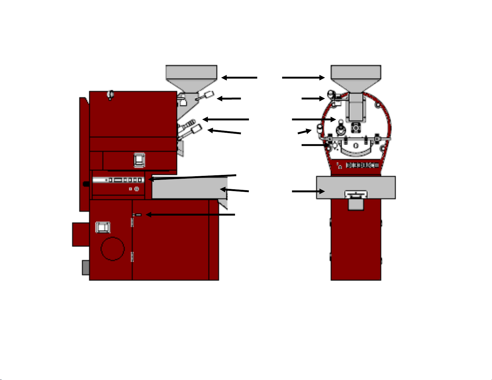
IR-5 & IR-12 Roaster Components
Funnel
Hopper gate handle
Sample trowel
Drum door handle
Burner view window
Operator control panel
Cooling bin
Airflow control handle
Page 5 of 23
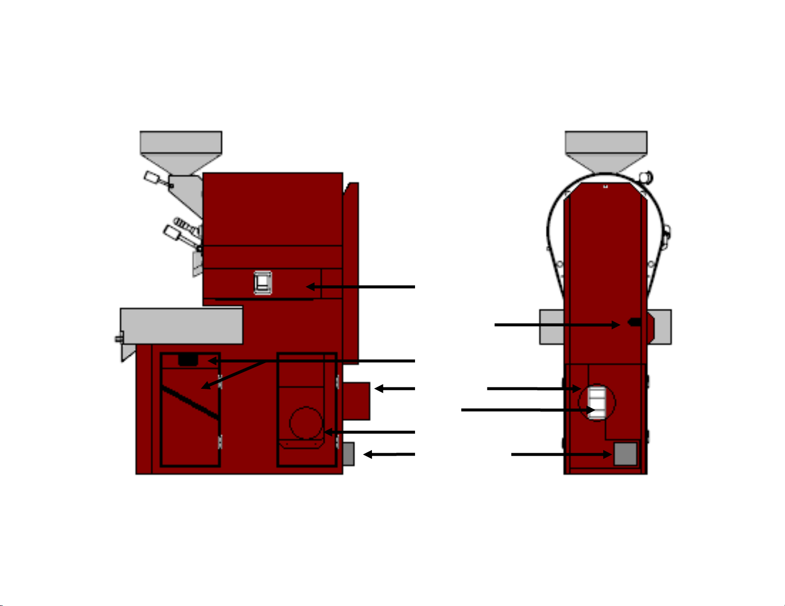
IR-5 & IR-12 Roaster Components
Burner & chaff tray
access door
Gas supply inlet
Cooling bin tray &
chaff compartment
Exhaust outlet
Impeller
Fan shroud
6” x 6” electrical box
Page 6 of 23
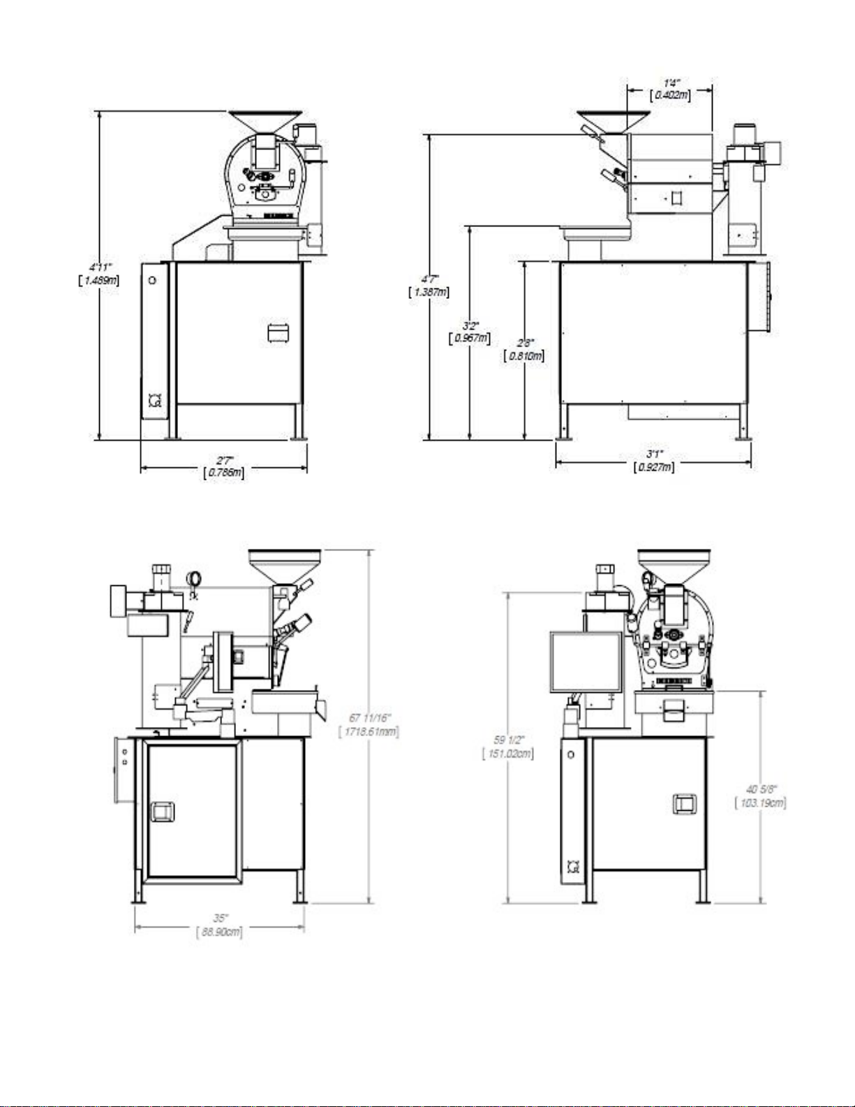
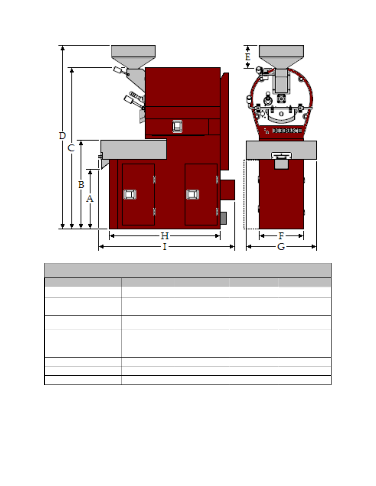
Roaster Dimensions
Inches / Centimeters
IR-1
IR-2.5
IR-5
IR-12
A: Chute Height
NA
8-3/4”/22.22cm
24.5" / 62.2cm
24.5" / 62.2cm
B: Bin Height
32” / 81.28cm
41” / 104.14cm
35.25" / 89.5cm
36.25" / 92.1cm
C: Roaster Height
55” / 139.7cm
59.5”/151.02cm
64" / 162.5cm
66.5" / 168.9cm
D: Roaster Overall Height
with Funnel
59” / 149.86cm
66”/151.02cm
70.5" / 179.1cm
77" / 195.6cm
E: Funnel Height
8” / 20.32cm
8” / 20.32cm
6.5" / 16.5cm
10.5" / 26.7cm
F: Compartment Width
13-1/4”/33.65cm
13-1/4”/33.65cm
18" / 45.7 cm
18" / 45.7cm
G: Cooling Bin Diameter
14-1/2”/36.83cm
16” / 40.64cm
25" / 63.5cm
29" / 73.66cm
G: Overall Width
28”/71.12cm
28”/71.12cm
26.5” / 67.3cm
29" / 73.66cm
H: Compartment Length
37”/93.98cm
37”/93.98cm
42" / 106.7cm
45" / 114.3cm
I: Overall Length
43”/109.22cm
43”/109.22cm
50" / 127cm
55" / 139.7cm

Page 7 of 23
Installation Hook-up Dimensions for Exhaust Duct and Electrical Junction Box
Roaster Models - Dimensions in Inches / Centimeters
IR-1
IR-2.5
IR-5
IR-12
A: Exhaust Air Outlet Height
47”/1193.8
55.5”/1409.7
16” / 44.5mm
16” / 44.5mm
B: Exhaust Air Outlet (Centerline
from back left side)
4”/101.60
6”/152.40
7.5” / 19.1mm
7.5” / 19.1mm
C: Electrical Junction Box Height
9”/228.60
9”228.60
9” / 22.8mm
9” / 22.8mm
D: Gas Inlet
1.55”/3.94
1.70”/4.32
30.5” / 77.5mm
30.5” / 77.5mm
Non-restrictive
exhaust cap
Check with local
codes and duct
manufacturer for
clearances to
walls
Minimum 8” clearance for
access to roaster components
Page 8 of 23
3. INSTALLATION INSTRUCTIONS
3.1 RECEIVING AND UNPACKING SHIPMENT
Upon receipt of your roaster immediately check for crate damage. Do not refuse shipment if damage is
evident. Make notes of damage on the appropriate shipping forms and take photos. Uncrate and look for
damage to the roaster; i.e., dents, scratches or chipped paint, and if found, immediately file a claim with the
appropriate freight carrier.
Locate the roaster where operation and coffee roasting can be observed in natural light or under consistent
light conditions. Natural light is essential for best results when observing the true color changes coffees
undergo during roasting. The use of a full-spectrum fluorescent light to simulate the full color of sunlight is
recommended for consistency in roasting.
After uncrating your roaster, if it becomes evident that movement may be hindered while moving it to its
installation location, detach and remove the cooling bin.
If the roaster is automated, mount the computer monitor onto the arm using the supplied Allen key.
3.2 LEVELING
The floor must meet weight-bearing requirements of local codes. Refer to the specifications chart for floor
bearing weights.
3.3 PROXIMITY TO WALLS
Failure to abide by required clearances will void your Diedrich warranty. No cabinets or storage areas are
to be installed over the roaster or near the ducting.
Make sure all controls, access doors, and inspection panels are accessible and can be opened without
restriction.
ATTENTION
Professional installation is required. Your Diedrich Roaster is designed for ease of installation and
simplicity of operation. Read these instructions completely before starting installation. Your local
building authority should be contacted to obtain local codes and installation requirements before
installing your roaster.
DANGER
Clearance from the roaster to adjacent walls, counters or other appliances must be at
least 18-inches (46 cm) or greater to ensure adequate cooling of the roaster and
adjacent walls.
This roaster MUST be installed on a flat/level, and noncombustible floor.
Page 9 of 23
4. GAS INSTALLATION
Gas installation MUST conform to local codes, regulations, and/or laws.
The gas supply line MUST be sized to accommodate the total length of the run and to accommodate any
required elbows. The line MUST be no less than the roaster's inlet size.
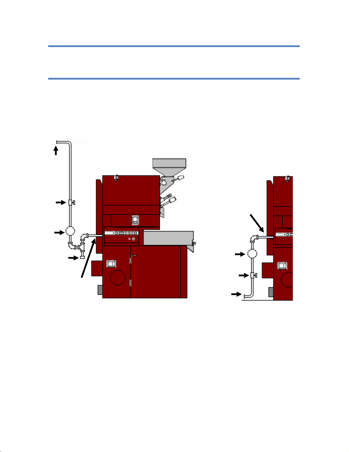
A water trap to collect condensation and loose particles should be installed in the gas supply line upstream
from the roaster.
Possible installation of Gas Lines
4.1 SAFETY SHUT-OFF VALVE
A safety shut-off valve MUST be installed in the gas supply line close to the roaster and pressure
regulator and in a location where it can be reached quickly in case of an emergency. The shut-off
MUST be marked to identify it as the gas shut-off.
Gas
shut-off
valve
To gas source
Pressure
regulator
Condensation
trap
Roaster gas inlet
Roaster gas inlet
To gas source
Gas
shut-off
valve
Pressure
regulator
ATTENTION
Use a licensed gas company for the gas line installation.

Page 10 of 23
4.2 PRESSURE REGULATOR
The roaster’s factory installed valve is preset for the BTU requirements of the roaster burners. The
valve in the roaster is not intended to reduce incoming pressure. A pressure regulator MUST be
installed before the roaster to reduce the incoming pressure. Your gas technician will be able
to provide the correct regulator for the specific installation.
Locate the regulator on the incoming gas supply line between the safety shut-off valve and the
roaster’s gas inlet. Diedrich recommends 8 to 14 inches WC (20 – 34.8 mbars) for natural gas and
12 to 14 inches WC (30 –34.8 mbars) for liquid propane at the roaster’s gas inlet. These pressures
are ideal for optimal performance.
NOTE: The manometer on top of the roaster measures the burner manifold pressure and not the
incoming pressure. When the burners are set at maximum gain the manometer should read
approximately 7-inches WC (16 mbars) for natural gas and 11-inches WC (27.4 mbars) for liquid
propane.
4.3 PIPE SIZING
IMPORTANT: When the gas installation is complete have your gas technician check the gas pressure at
the point where the gas line connects to the roaster. The roaster and/or afterburner and any other
appliances connected to the gas line should be running at the full flame setting for this test (See Orifice
Sizes and Testing Specifications table below).
The valve may experience damage if the incoming line pressure to the roaster
exceeds 20-inches WC (50 mbars). An external pressure regulator is required to
limit incoming gas pressure.
Sizing of the gas supply line is critical to the roasters performance. Ensure the gas
supply line is sized in accordance with the maximum BTU demands of the roaster and
any other appliances connected to the gas line.
The roaster must be isolated from the gas supply line by closing the safety shut-off
valve during any pressure testing of the gas supply line.
If the installation has both a roaster and an oxidizer, a separate incoming
pressure regulator MUST be used for each piece of equipment.

Page 11 of 23
Roaster
Gas
Orifice
Max Manifold
Pressure
Inlet Pressure
Gas
Consumption
High Fire Allowable
Range
"WC
mbar
"WC
mbar
BTU/Hr
KW
Plus 5%
Minus 5%
IR-12
LP
1.9mm
11
27
12 - 14
30 - 35
90,000
26
85,500.00
94,500.00
N
35
6
15
8 - 9
20 - 22.5
90,000
26
85,500.00
94,500.00
IR-5
LP
1.45mm
11
27
12 - 14
30 - 35
50,000
15
47,500.00
52,500.00
N
47
7
17
10 - 12
25 - 30
50,000
15
47,500.00
52,500.00
IR-2.5
LP
59
11
27
12 - 14
30 - 35
24,000
7
22,800.00
25,200.00
N
55
7
17
10 - 12
25 - 30
24,000
7
22,800.00
25,200.00
IR-1
LP
64
11
27
12 - 14
30 - 35
10,000
3
9,500.00
10,500.00
N
55
7
17
10 - 12
25 - 30
10,000
3
9,500.00
10,500.00
4.4 GAS INSTALLATION
Before placing the roaster in operation, always check connections for gas leaks with a soapy water
solution or other acceptable method.
Do not remove any labels, warnings or rating plates from the roaster or from its components as this
may void manufacturer's and Diedrich Roaster’s warranties.
5. ELECTRICAL INSTALLATION
Electrical installation must conform to local regulations. Some roasters must be hard-wired (pipe
conduit with grounding wire) from the electrical source to the roaster.
Do not remove any labels, warnings or rating plates from the roaster or from its components as this
may void manufacturer's and Diedrich Roaster’s warranties.
Some automated roasters have the ability to control optional equipment (i.e., loader and/or
destoner. Each of these options will require an additional dedicated circuit separate from
the roaster circuit.
ATTENTION
Use a licensed electrician for the electrical installation.
DANGER
DO NOT USE AN OPEN FLAME TO CHECK FOR LEAKS!
DANGER
This roaster must be electrically grounded in accordance with local codes. A
severe shock hazard exists if the electrical source is not grounded or if the
polarity is reversed.

Page 12 of 23
All electrical components supplied in the roaster are grounded electrically to the roaster frame.
6. CYCLONE TO ROASTER CONNECTIONS
(Applies to IR-1 & IR-2.5 ONLY) Connect the blower motor cord as shown in the photo below.
6.1 ROASTER EXHAUST DUCTING
One of the most important aspects of the roaster installation is the use of an approved ducting system. Its
design will greatly affect the performance of the roaster and the product quality. Two considerations when
designing a ducting system are the static pressure and the distance the ducting is to combustible/non-
combustible materials.
All makes of roasters and oxidizers have a blower mounted inside which forces exhaust air into the ducting.
The oils and residues in the exhaust air are flammable. In the event of a ducting/flue fire, the internal duct
temperatures can exceed 1000° F (538°C), which could cause nearby combustible materials to ignite. For
this reason, Diedrich recommends, at a minimum, stainless steel, double wall, positive pressure grease
ducting (UL certified for USA and Canada, or CE for European Union).
•ROASTER: Ducting must be suitable for 1000°F (538°C) continuous and 1400°F (760°C)
intermittent operating temperatures.
•OXIDIZER: Ducting must be suitable for 1400°F (538°C) continuous.
Attach the blower motor cord to the
receptacle on the motor assembly.
DANGER
A safety shut-off must be installed in the electrical supply line near the roaster‘s
junction box where it is easily accessible by the operator.
Page 13 of 23
The exhaust system must be designed to operate with a static flue pressure between negative 0.15”WC
and positive 0.25”WC at the exhaust of the roaster while in operation.
Check local codes to determine the requirements specific to your location.
Designing an exhaust system requires a trained professional to calculate the efficiency of the system and
proper size of duct. The ducting must be of sufficient diameter to accommodate the SCFM (standard cubic
feet per minute) or SCMH (standard cubic meters per hour) of airflow. A licensed Heating, Ventilation, Air
Conditioning (HVAC) professional can assist you with the best ducting layout for your site. Pertinent
information relating to the diameter of the exhaust ducting on the roaster and the maximum exhaust air flow
in SCFM is located in the Basic Specifications table at the beginning of this manual.
When venting your roaster, a direct vertical run is typically the most efficient and cost effective. The design
of the building may dictate the use of 45° or 90° elbows which will put a restriction on the airflow and may
cause unwanted backpressure on the roaster. If spacing permits, use two 45° elbows rather than a 90°
elbow to reduce restriction. A booster fan may be needed to assist air movement if the system is too
restrictive. A qualified ducting contractor/engineer will determine the best design for your specific
installation.
The roaster MUST NOT support the weight of the exhaust system. Ducting must be connected to the
roaster based on the ducting manufacturer’s recommendation.
A properly designed and installed chimney and rain cap is essential to the overall design. Water leaking in
may cause an electrical short or damage the equipment. Your contractor will be able to coordinate with
local jurisdictions for the correct cap. The cap should not have a screen since it will clog with residue of
chaff over time.
Consult the services of a ducting manufacturer to determine the best venting option for your setup. Your
HVAC installer may also have a recommendation or preferred manufacturer. Positive pressure grease
vents are not an off-the-shelf product so plan ahead to compensate for long lead times.
6.2 INSTALLATION INSPECTION
DANGER
DO NOT USE CLASS B OR SPIRAL-WRAP DUCTING UNDER ANY CIRCUMSTANCES.
DANGER
Fires are caused by failure to maintain a clean roaster and its exhaust ducting
system. Regular cleaning of the roaster and exhaust ducting will prevent the
buildup of residues that could cause fire.
ATTENTION
The completed roaster installation MUST BE INSPECTED for compliance to codes and by your local fire
department PRIOR TO OPERATING THE ROASTER. Failure to have these inspections performed will
void the warranty and will relieve Diedrich of any liability associated with the installation and use of our
products.
Page 14 of 23
7. OPERATIONS
7.1 ROASTER PARTS
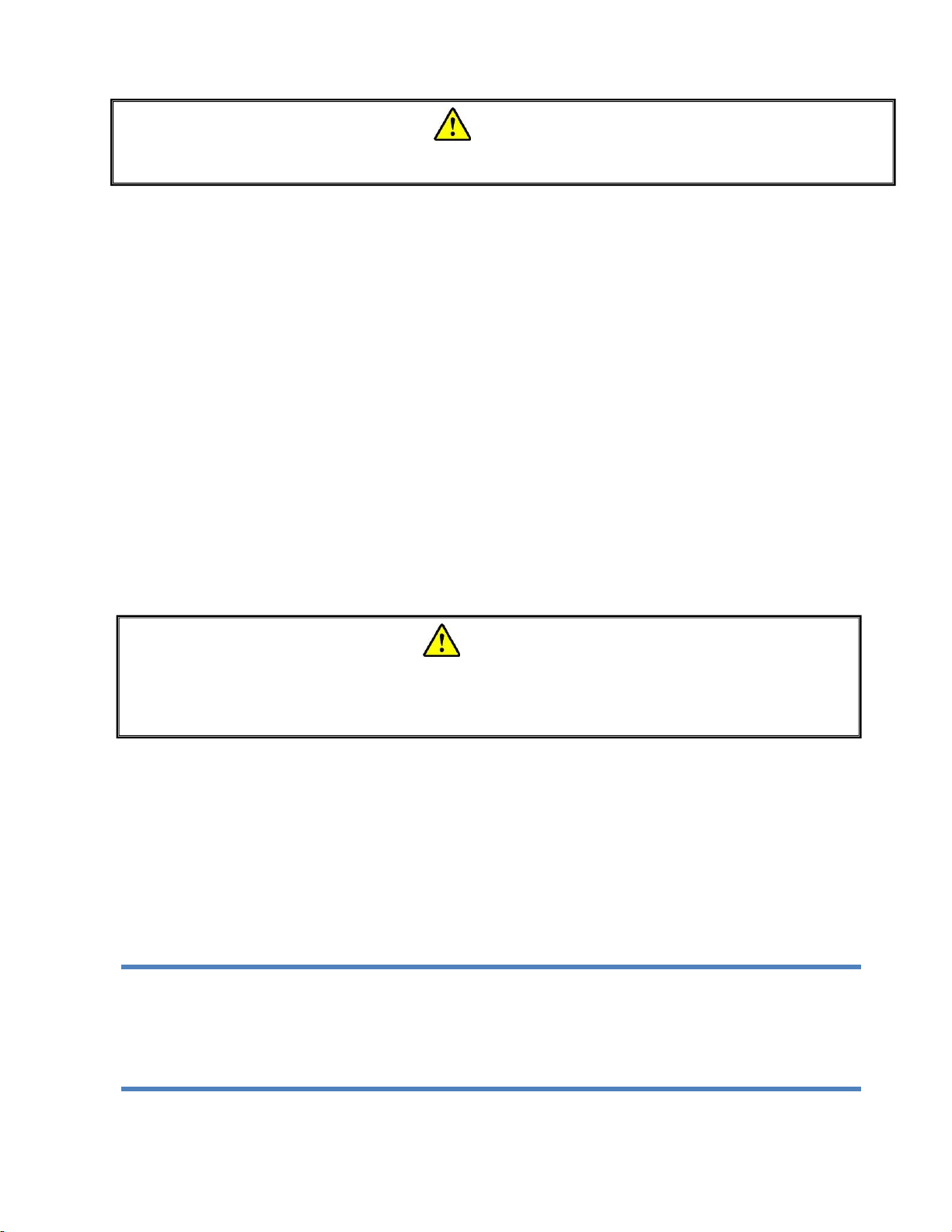
7.2 AIR FLOW POSITIONS
“Through Roasting Drum” “50/50” “Through Cooling Bin”
Drum Door
View Window
Burner View
Window
Hopper
Gate Handle
Drum Door
Handle
Page 15 of 23
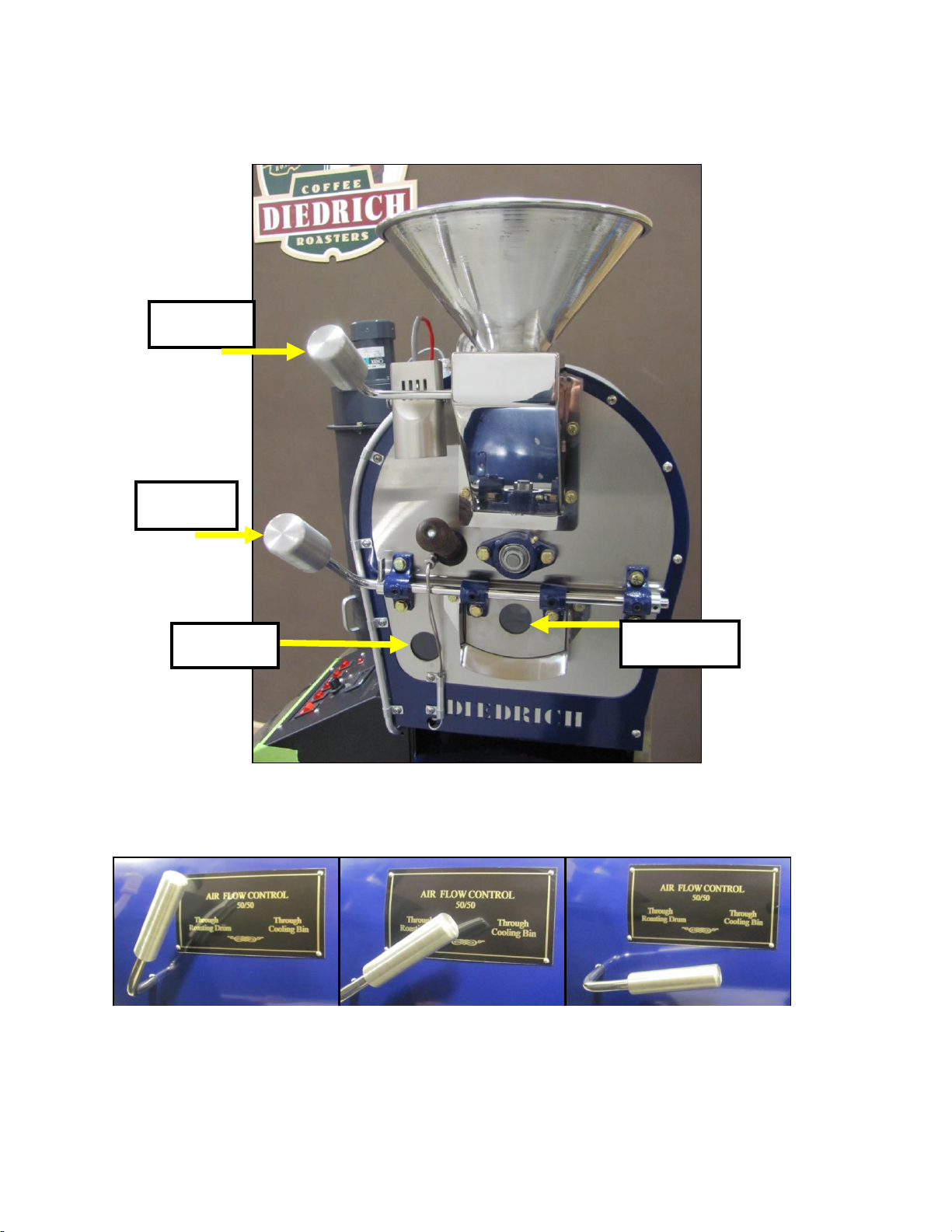
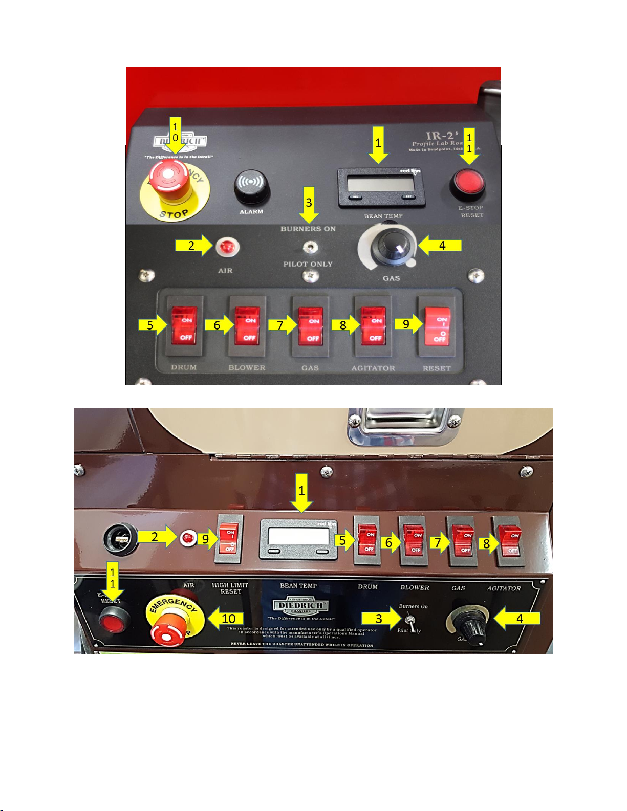
7.3 OPERATOR CONTROL PANEL.
IR-1 & IR-2.5 (Manual)
IR-5 & IR-12 (Manual)
7.4 COMPONENT DESCRIPTION
1. BEAN TEMP display: This is the temperature of the beans in the drum.
2. AIR light: This light may be on or off depending on the model of roaster.
Standard model roasters have a red light. If it is illuminated there is an air flow restriction and the
roaster will not ignite the burners.

Page 16 of 23
Universal model roasters have a blue air light. This light will be illuminated during normal
operation. If it is NOT illuminated there may be a draft in the exhaust ducting and the roaster will
not ignite the burners.
3. Pilot Only/Burners On toggle switch: This switch toggles the main burners on and off. If lower
than the minimum GAS knob setting is required, the operator can turn the main burners off.
4. GAS knob: This knob controls the flame level. The intensity can be viewed through the window
below the sample trowel and gas pressure on the manometer on the top or the roaster.
5. DRUM switch: This switch starts the drum spinning.
6. BLOWER switch: This switch starts the blower fan.
7. GAS switch: This switch turns on the gas.
8. AGITATOR switch: This switch turns on the agitator in the cooling bin.
9. RESET switch: This switch will reset the high limit safety module if the temperature climbs above
485°F (252°C).
10. Emergency Stop: This button is to be pushed in case of an emergency.
11. E-Stop Reset: Push this button to reset the roaster after pushing the “Emergency Stop” (10)
button.
8. INITIAL START-UP
8.1 LIGHTING THE PILOT BURNER
The pilot burner is a small flame which is in between the main burners. It looks like three small
candle flames and can be seen through the view window below the sample trowel.
Follow these steps to ignite the pilot burner: (Numbers ( ) correspond to the picture in section 7.3,
Operator Control Panel above.
1) Ensure the “Pilot Only/Burners On” (3) switch is in the "Pilot Only" position.
2) Verify that the air flow handle in the Cooling Bin position.
3) Confirm that the “GAS” knob (4) is turned all the way to the right (clockwise).
NOTE: Standard model roasters and Universal model roasters have different start-up procedures.
A Standard roaster has a red air light on the control panel a serial number that starts with “S”. A
Universal roaster has a blue air light on the control panel and a serial number that starts with “U”.
ATTENTION
At 475°F (246°C) - the main burner shuts off, but the pilot DOES NOT (No alarm will sound). At 485°F
or 252°C- the alarm will sound and the Excess Temperature limit will shut down the roaster's entire gas
system. You will have to reset the roaster once it has cooled down below the Excess Temperature
limit. To restart the burners, follow the normal start up procedure.
DANGER
A possibility of fire exists if the coffee is not removed from the drum before 500°f
(260c). The coffee may ignite even if the flame was turned off at 485°f (252°c).
ATTENTION
Make sure the “Emergency Stop” button is not engaged before performing the steps below.

Page 17 of 23
4) Lighting the burners:
a) For Standard roasters: (Standard roasters have a serial number which starts with
“S”.)
Turn on the switches in the following order:
•Drum (5)
•Blower (6)
•Gas (7)
NOTE: The igniter will spark until the pilot burner ignites or for a maximum 90 seconds. If the pilot
does not ignite turn the GAS switch (7) “OFF”, wait a minimum of 5 minutes, and then attempt to
relight the appliance.
b) For Universal roasters: Universal roasters have a serial number which starts with
“U”.
Turn on the switches in the following order:
•Drum (5)
•Gas (7)
•Wait for the BLUE air light to come on then turn on the Blower (6) switch.
NOTE: After the roaster will goes through a 30 second purge cycle the igniter
will start to spark. Should the pilot fail to light, shut off the blower and gas
switches, wait a minimum of 5-minutes, and then attempt to reight the
appliance. NOTE The blower MUST stop turning before attempting to
light the roaster again.
5) All roasters: Once the pilot is lit, switch to the "Burners On" (3) position and use the gas control
knob to adjust the flame intensity
NOTE: The first time the pilot ignites extra time may be necessary to allow air to bleed out of the
gas line. Following the ignition of the pilot, two to three minutes may be required to allow the two
infrared burners to ignite for the first time. Watch through the view window for burner ignition.
6) Move the Gas (7) knob to the desired flame setting and monitorthe Bean Temperature Display
(1).
7) Allow the roaster warm to 400°F - 450°F, (204°C - 232°C).
NOTE: If no grinding sounds occur up to 415°F, the initial warm-up is complete and roasting can
begin. If there is a grinding sound, turn “OFF” the drum motor (5) and contact the Diedrich Roasters
Technical Support for instructions.
8) Check the exhaust system for leaks.
NOTE: If leaks are present, the ventilation contractor must be contacted to correct the situation.
9. ROASTING
The instructions below explain the operation of the roaster. They are not an attempt to teach all the
subtleties and proper techniques of roasting the many varieties of coffee beans. Further information on
roasting is available during the Diedrich Roasters roasting seminars.
Average roasting times are from 14 -15 minutes for a light roast and 15-18 minutes for a darker roast,
depending on the source or type of beans. Reducing the burner flame is one of several ways to lengthen
roast times. The temperature of the roasting system (comprised of the coffee beans, roasting drum, and
end plates) reacts slower than the flame adjustments. Do not expect an immediate temperature change
when the heat level is changed. After a short time, the beans and roasting system will show signs of
dissipating heat.
Other manuals for IR Series
1
This manual suits for next models
4
Table of contents
Other Diedrich Roasters Kitchen Appliance manuals


