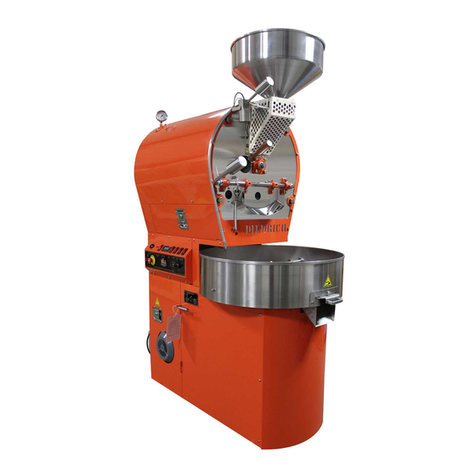
Diedrich Roasters IR-7 User manual

DIEDRICH COFFEE ROASTER
OWNER'S MANUAL
For Models IR-7, IR-12 and IR-24
(Standard)
Issued: February 1991
Reissued: August 2008
DIEDRICH MANUFACTURING, INC
P.O. Box 430
Ponderay, Idaho 83852
Telephone: (208) 263-1276
FAX: (208) 265-4584
Copyright © 2007 by Diedrich Manufacturing, Inc
PROPRIETARY RIGHTS NOTICE: All rights reserved. No part of this material may be reproduced or transmitted
in any form or by means, electronic, mechanical or otherwise, including photocopy and recording or in connection
with any information storage or retrieval system, without the written permission of Diedrich Manufacturing, Inc.
READ THIS MANUAL
For important safety, installation,
operation and maintenance instructions.
Keep this manual with the roaster at all
times. Locate in a prominent place.
“The Difference is in the Detail”
MANUFACTURING


TABLE OF CONTENTS
Page
PREFACE v
1.0 IMPORTANT SAFEGUARDS 1
2.0 INSTALLATION INSTRUCTIONS 7
2.1 Receiving and Unpacking Shipment 7
2.2 Leveling 7
2.3 Proximity to Walls 8
2.4 Gas Installation 8
2.5 Electrical Installation 12
2.6 Roaster Exhaust Ducting 12
2.7 Installation Inspection 15
3.0 INITIAL START-UP (for Drum seating) 16
4.0 SEASONING THE ROASTING DRUM 18
5.0 START-UP (for Roasting) 20
6.0 ROASTING (for consumption) 21
7.0 SHUT-DOWN (after last roast) 25
8.0 ROASTING AND CLEANING LOG 26
9.0 CLEANING 29
9.1 General 29
9.2 Daily Basis 31
9.3 After every 12 hours 31
9.4 Every two weeks 31
9.5 After 40 hours of roasting 31
9.6 Lower Compartments 31
9.7 Drum Chaff Tray 32
9.8 Cooling Bin 32
9.9 Blower Impeller 32
9.10 Chaff Collector Duct 33
9.11 Roaster Exhaust Duct 33
9.12 General Cleaning 34
iii

iv
TABLE OF CONTENTS
- Continued Page
10.0 MAINTENANCE 35
10.1 Suggested Hand Tools and Lubricants 35
10.2 Blower Motor 36
10.3 Agitator Motor 36
10.4 Drum Motor 36
10.5 Roasting Drum Drive Chain 36
10.6 Roasting Drum Drive Chain Adjustment 36
10.7 Front and Rear Drum Bearings 40
10.8 Burner & Drum Chaff Tray Access Doors 40
10.9 Agitator Drive Shaft Universal Joint 40
10.10 Agitator Brush Assembly Adjustment 40
10.11 Air Flow Control Handle 41
10.12 Cooling Bin 41
11.0 FIRE CONTROL - Action to take (Checklist) 45
LIST OF ILLUSTRATIONS AND TABLES
Figure 1 - Roaster Left Side and Front End Views 3
Figure 2 - Roaster Right Side and Rear End Views 4
Figure 3 - Roaster Basic Dimensions 6
Figure 4 - Installation Hook-up for Gas Lines 9
Figure 5 - Installation Hook-up Dimensions for Exhaust Duct
and Electrical Junction Box 13
Figure 6 - Operating Control Panel 17
Figure 7 - Air Flow Control Handle 22
Figure 8 - Typical Entries into Roasting and Cleaning Log 27
Figure 9 - Blower Motors and Impeller 37
Figure 10 - Agitation Motors and Drive Shaft 38
Figure 11 - Drum Motor 39
Figure 12 - Removal of Cooling Bin 42
Figure 13 - Electrical Wiring Diagram 43
Figure 14 - Gas System - Basic 44
Table A - Basic Specifications 5
Table B - Diedrich Roasting and Cleaning Log 27 & 28
Table C - Roaster Cleaning Schedule 30
Table D - Roaster Service Schedule 36

v
PREFACE
This owner's manual covers installation, operation and maintenance as well as important
safeguards of the Diedrich Coffee Roaster. The information described reflects the features
found on current production models.
The Diedrich IR-7, IR-12, and IR-24 Coffee Roasters are all identical in construction detail
and features offered. They differ only in scale so the descriptions provided in this Manual are
generic and if differences exist, they will be specifically mentioned.
This manual covers all of the components which make up a coffee roaster. If you have any
questions about the roaster, its accessories, or the proper use of them and they are not answered
in this manual contact Diedrich Manufacturing, Inc.
Over the years, Diedrich Coffee Roasters have undergone an evolutionary design process. As
new technologies have become available they have been incorporated. As the demands of the
modern market have changed, Diedrich Manufacturing, Inc. has found ways to meet them while
maintaining the fundamental principles by which premium coffee is roasted for optimum cup
quality.
The Diedrich IR Series Coffee Roasters feature a highly efficient gas-infrared heating system,
which is combined with the non-perforated, carbon steel roasting drum to heat the coffee beans
evenly and achieve optimum roasting standards.
This manual is not necessarily intended to teach one how to roast coffee but does describe the
proper techniques to operate the Diedrich Coffee Roaster.

1
1.0 IMPORTANT SAFEGUARDS
Proper installation, cleaning and safe operation of the coffee roaster is the owner’s and
operator’s responsibility. Read this manual carefully for important operation,
maintenance and safety information.
This owners manual must be kept with the roaster at all times and be located in a
prominent, easily accessible place. The contents of the manual, including the fire control
instructions described in Section 11 Fire Control must be reviewed regularly by all
operators of this roasting system.
All persons operating the Diedrich Coffee Roaster must be familiar with this manual and
be properly trained in the safe and proper use of the roasting system. The safe use of
this equipment also requires an understanding of the basic chemistries that occur
during the roasting process so that subtle warnings can be identified before critical
problems arise.
The roaster’s internal compartments should be cleaned on a daily basis and more
thoroughly cleaned after every 60 hours of use. More frequent cleaning may be required
if chaff and residue build-up becomes excessive. Refer to Section 9.0 Cleaning for
detailed instructions.
CAUTION - Always be aware of the risk of a fire. Fires are caused by failure to
maintain a clean roaster and its exhaust duct system. A dirty roaster will also
affect the efficiency of the roasting process. We cannot over-emphasize the
importance of a safe installation that is kept clean!
A fire extinguisher should be located within easy reach of the roasting system. This
should preferably be CO2 extinguisher with sufficient capacity for a roasting fire.
Consult with your local fire marshal for recommendations on suitable fire extinguishers.
You should also have water accessible near the roaster. If a water hose installation is not
possible, a two-gallon water sprayer is recommended. If water is used, great care must be
taken to keep the water away from the electrical system.
Never leave the roaster unattended while it is in operation...from start-up to shutdown.
Leave the drum and blower motors running until the temperatures have dropped below
200 ° Fahrenheit (93 ° Celsius). Prior to leaving the roaster, perform all necessary post-
roasting cleaning.

2
Never, under ANY circumstances while operating or servicing the machine, thrust a
hand or arm into the roasting drum or any other access port until the roaster is
switched “OFF” and disconnected at its electrical source. Keep clear of moving parts
such as the drive chain at the rear of the roaster and the agitator arm and brushes in the
cooling bin if so equipped. Injury can result from snagged, loose clothing, jewelry, hair
or fingers.
Never permit an unqualified person to operate the roaster. A qualified operator will have
thoroughly read this manual. All qualified operators must have a clear understanding of
the proper and intended use of the equipment, roasting methods, cleaning requirements,
fire suppression procedures and be aware of all safety precautions.
Keep your customers clear of the roaster when it is operating. They may not be aware of
potential hazards.
Keep the roasting area clear and free of combustible material.
Install a CO Monitor when roasting or storing roasted coffee in confined spaces due to
the emission of carbon monoxide.
During and after the roasting, take care when touching the roaster’s exterior surfaces.
The upper half of the front plate can be very hot while the lower half is usually very
warm. The painted mantle encasing the roasting drum is warm to the touch during
roasting. The cooling bin becomes hot when cooling freshly roasted beans.
FIRE CONTROL - Be sure to read and understand. PRACTICE!! Refer to
Section 11.0

3

4

5
TABLE A -
IR Series Basic Specifications
Description Unit of Model Model Model
Measure IR-7 IR-12 IR-24
Single Roast Range lbs 1-15 1-30 1-52
kg .453 / 7 .453 / 12 .453 / 24
* Hourly Roast Output lbs 53.9 92.4 184.8
(maximum) kg 23 46 99
Roaster Weight Empty lbs 880 960 1960
kg 400 436 890
Floor Bearing Weight lbs 895 990 2015
with maximum load of beans kg 406 446 907
Floor Space Required inches 26.5 x 50 29 x 58 38.5 x 64
includes exhaust air outlet centimeters
67.3 x
127
73.7 x
147.3
97.8 x
162.6
Roaster Overall Height inches 79 79 84.25
with funnel centimeters 201 201 214
Roaster Overall Length inches 42 42 61.75
with exhaust outlet centimeters 107 106.6 156.94
Roaster Overall Width inches 26.5 30.5 38.5
centimeters 67.3 77.47 97.79
Gas Consumption BTU/Hour 36,000 60,000 124,000
Gas Connection Inches NPT 1/2 1/2 3/4
MM NPT 13 13 19
Electric Supply Volts AC - U.S.A. 110-60Hz 110-60Hz 110-60Hz
Volts AC - International 220-50Hz 220-50Hz 220-50Hz
Amperage 110 V AC 9.8FLA 9.8FLA 26 FLA
220 V AC 5FLA 5FLA 22 FLA
Exhaust Duct Air Flow Cubic Feet Minute (SCFM) 480 480 945
Cubic Meters Second m3/hr 816 816 1606
Exhaust Duct Diameters inches 6 6 8
*Based on maximum load every 16
minutes at 425 degrees F (218 degrees
C) for 15% weight loss. centimeters 15.24 15.24 20.32

6
Roaster Models - Dimensions
Inches / Centimeters
IR-7 IR-12 IR-24
A: Chute Height 23.5" / 59.7 24.5" / 62.23cm 26" / 66.04cm
B: Bin Height 33.25" / 84.5 36.25" / 92.07cm 39" / 99.06cm
C: Overall Height 79" / 201cm 66.5" / 168.91cm 71.99" / 182.85cm
D: Funnel Height 10.5" / 26.67cm 10.5" / 26.67cm 12.25" / 31.11cm
E: Compartment Width 18" / 46 cm 18" / 45.72cm 24" / 60.96cm
F: Cooling Bin Diameter 26.75" / 69cm 29" / 73.66cm 38" / 96.52cm
G: Compartment Length 42" / 107cm 42" / 106.68cm 53.5" / 135.89cm
H: Overall Length 47.25" / 120.01cm 49.75" / 126.36cm 61.75" / 156.84

7
2.0 INSTALLATION INSTRUCTIONS
IMPORTANT: The Diedrich Coffee Roaster is designed and manufactured for ease of
installation and simplicity of operation. However, professional installation is required.
The installer should read the instructions completely before starting the installation to
save time, ensure good performance and owner's warranty protection. We recommend
that the local Building Department be contacted to obtain local codes and installation
requirements.
2.1 RECEIVING AND UNPACKING SHIPMENT
When the roaster is received, immediately check for crate damage. Do not refuse
shipment if damage is evident. Make notes of such on the appropriate shipping forms.
Uncrate and look for damage to the roaster; i.e., dents, scratches or chipped paint, and if
found, immediately file a claim with the appropriate freight carrier. Photo documentation
of damaged areas is suggested!
Locate the roaster where its operation and coffee roasting can be observed in natural light
or under consistent light conditions. To detect the true color changes which beans
undergo during roasting, natural light is essential for best results. For consistency in
roasting, the use of a full-spectrum fluorescent light to simulate the full color of sunlight
is recommended.
When moving the uncrated roaster to its installation location and a narrow doorway
hinders movement, detach and remove the cooling bin. To determine clearances refer to
Figure 3 for cooling bin diameters. Refer to Paragraph 10.12 for disassembly and
assembly instructions.
2.2 LEVELING
The roaster must be installed on a flat, non-combustible floor. A combustible floor
requires a fireproof insulation on the floor areas occupied by the roaster. The floor must
meet weight-bearing requirements of local codes for commercial buildings. Roaster
gross weight with maximum load of coffee beans:
Model IR-7 …….......895 lb / 406 kgs
Model IR-12………..990 lb / 450 kgs
Model IR-24……....2005 lb / 911.4 kgs
Careful leveling of the roaster is critical not only for performance but for alignment of the
roasting drum. Use a carpenter's level.
For side-to-side leveling, set level crossways on top of the cooling bin. Shim roaster as
required to level.

8
2.0 INSTALLATION INSTRUCTIONS (Continued)
2.2 LEVELING (continued)
For front-to-back leveling, set level lengthwise on top of cooling bin (at 90° from side-to-
side leveling). Shim roaster as required to level. Non-combustible shims are required
under the roaster.
2.3 PROXIMITY TO WALLS
Due to the extended daily use of the roaster, clearances to combustible or non-
combustible walls or counters listed below must be followed to ensure adequate cooling
of the roaster and adjacent walls. Failure to abide by these clearances will void the
manufacturer's warranty.
2.3.1 Clearance from roaster to adjacent walls, counters or other appliances must be at least
18” (46 cm) or greater. No cabinets or storage areas are to be installed over the roaster or
near the ducting.
2.3.2 Positive Pressure Grease Ducting clearances are defined by the manufacturer. Follow the
manufacturer’s specifications on minimum clearance from combustibles and non-
combustibles.
2.3.3 Make sure all controls, access doors and removable panels on the roaster area are
accessible and without restrictions.
2.4 GAS INSTALLATION - See Figures 4 & 14
Use a licensed contractor for the gas line installation.
Gas installation must conform to local, city, county, municipality, province, state, or
national building codes, regulations, or laws. It is imperative that your licensed gas
contractor is familiar with which building codes, regulations or laws apply.
The gas supply line must be sized to accommodate the total length of the run including
bends. The volume of gas needed to function properly is determined by the maximum
BTU requirements for the roaster.
A water trap to collect condensation and loose particles should be installed in the gas
supply line upstream from the roaster. See Figure 4.
2.0 INSTALLATION INSTRUCTIONS
2.4 GAS INSTALLATION (continued)

9
2.4.1 SAFETY SHUT-OFF VALVE
A safety shut-off valve must be installed in the gas supply line close to the roaster and
pressure regulator and in a location where it can be reached quickly in an emergency. In an
emergency any operator, qualified or not, can turn off the gas flow to the roaster. The safety
shut-off valve must be approved by UL in USA, AGA in Australia, CSA in Canada, or CE
in the European Union.
2.4.2 PRESSURE REGULATOR
The roaster’s factory installed regulator is preset to the pressure requirements of the roasters
burners. Damage to the regulator can be caused if the incoming line pressure to the roaster
exceeds 14” WCL (35 mbars). If the incoming gas pressure is in excess of 14” WCL (35
mbars), then a pressure regulator is required. Locate the regulator on the incoming gas
supply line between the safety shut-off valve (See Figure 4) and the roaster’s gas inlet.
Diedrich Manufacturing, Inc. recommends 7” to 8” WCL (17.5 – 20 mbars) for Natural Gas
and 11” to 13” WCL (27.5 – 32.5 mbars) for Liquid Propane at the roaster’s gas inlet. These
pressures are ideal for an optimally running roaster.
2.0 INSTALLATION INSTRUCTIONS (Continued)
2.4 GAS INSTALLATION (Continued)

10
Note: The WCL measurement on the manometer located on the top of the coffee roaster
should read approximately 6” WCL (15 mbars) for Natural Gas and 10” WCL (25 mbars)
for Liquid Propane when the burners are on full.
2.4.3 FLEXIBLE CONNECTIONS
If the roaster is to be installed with flexible couplings and/or quick-disconnect fittings,
the installer must use heavy-duty design-certified commercial flexible connectors of at
least ½ inch (1.3 cm) NPT (with suitable strain relief).
2.4.4 GAS INSTALLATION CHECK-OUT
Sizing of the gas supply line to the roaster is critical for proper performance. Ensure a
licensed gas contractor or the gas company sizes the gas supply line in accordance with
the maximum BTU demands of the roaster and any other appliances connected to the gas
line. Check the roaster’s and/or afterburner’s data plaques for this information. Also,
take into account any other appliances such as water heaters, furnaces, etc. when sizing
the gas line.
The roaster must be isolated from the gas supply line by closing the safety shut-off valve
during any pressure testing of the gas supply line.
Before connection to the roaster, open the gas shut-off valve for gas flow to bleed air out
of the gas supply line. This ensures prompt ignition of the burners the first time the
roaster is started. After bleeding, close shut-off valve and connect piping to roaster.
IMPORTANT: When the gas installation is complete have your contractors check the
gas pressure at the point where the gas line connects to the roaster. The roaster and/or
afterburner and any other appliances connected to the gas line should be running at the
full flame setting for this test. The pressure at the roaster must be in compliance with
paragraph 2.4.2.
Before placing the roaster in operation, always check connections for gas leaks with a
soapy water solution or other acceptable method. DO NOT USE AN OPEN FLAME
TO CHECK FOR LEAKS!
Do not remove permanently affixed labels, warnings or rating plates from the roaster or
from its components, as this will void manufacturer's warranties and create hazardous
operating conditions.

11
2.4.5 WARNING LABELS
Note: These warning labels should be copied and posted in a prominent location for use in case
the user smells gas.
2.0 INSTALLATION INSTRUCTIONS (continued)
2.5 ELECTRICAL INSTALLATION (See Figures 5 and 12)
Use a locally licensed electrician for the electrical installation.
Electrical installation must conform to local, city, county, municipality, province, state,
and national building codes, regulations, or laws. It is imperative that your licensed
electrical contractor is familiar with which building codes, regulations, or laws apply.
The roaster must be hard-wired (pipe conduit with grounding wire) from the electrical
source to the roaster according to the name plate Full Load Amps and Voltage
WARNING
IF THE INFORMATION IN THIS DIEDRICH ROASTER OWNER’S MANUAL IS
NOT FOLLOWED EXACTLY, A FIRE OR EXPLOSION MAY RESULT CAUSING
PROPERTY DAMAGE, PERSONAL INJURY, OR DEATH.
1. Do not store or use gasoline or other flammable vapors and liquids in the vicinity of
this roaster or any other appliance.
2. WHAT TO DO IF YOU SMELL GAS:
*Do not try to light any appliance.
*Do not touch any electrical switch; do not use any phone in your
building.
*Immediately call your gas supplier from a neighbor’s phone.
*Follow the gas supplier’s instructions.
*If you cannot reach your gas supplier, call the fire department.
3. Installation and service must be performed by a qualified installer, service agency, or
the gas supplier.
WARNING
If this roaster is not installed, operated and maintained in accordance with the
Diedrich Roaster Owner’s Manual, you could be exposed to substances in fuel or
from fuel combustion which can cause death or serious illness and which are know
to cause cancer, birth defects or other reproductive harm.
For example, benzene is a chemical which is a part of the gas supplied to the cooking
product. It is consumed in the flame during combustion. However, exposure to a small
amount of benzene is possible if a gas leak occurs. Formaldehyde and soot are by-
products of incomplete combustion. Properly adjusted burners with a bluish rather than
yellow flame will minimize incomplete combustion.

12
Power connection for the IR-7, IR-12, and IR-24 manual control roasters is located in the
Electrical box mounted on the bottom rear of the roaster. The IR-7 and IR-12 automated
roasters are shipped with a power cord on the podium. The power connection for an IR-
24 automated roaster is located in the electrical box located under the bottom shelf inside
the podium.
WARNING! If the electrical source is not grounded or if the polarity is reversed, a
severe shock hazard will exist. All components in the roaster are grounded electrically to
the roaster frame.
2.6 ROASTER EXHAUST DUCTING (See Figure 5)
Compliance to local and national codes is critical for a proper installation
.
Installation should be preformed by a licensed qualified technician
USE ONLY DOUBLE-WALL, POSITIVE PRESSURE PS GREASE DUCTING
OR SINGLE-WALL, WELDED SEAM 18-GAUGE (1.3 mm thick) STEEL
DUCTING.
WARNING: DO NOT USE CLASS B OR SPIRAL-WRAP DUCTING UNDER ANY
CIRCUMSTANCES.
DIEDRICH MANUFACTURING, INC. RECOMMENDS THAT POSITIVE
PRESSURE GREASE DUCTING IS INSTALLED WITH CLEARANCES TO
THE DUCTING MANUFACTURER’S SPECIFICATIONS
Roaster Models - Dimensions in Inches & Centimeters
IR-7 IR-12 IR-24
A: Exhaust Air Outlet Height 16 / 40.6 17 / 43.2 21 / 53.3
B: Exhaust Air Outlet (Centerline from
back left side) 7.0 / 17.8 7.0 / 17.8 9.5 / 24.13
C: Electrical Junction Box Height 17.5 / 44.5 17.5 / 44.5 14.5 / 36.8
D: Gas Inlet (also see fig.5) 32.5 / 82.6 32.5 / 82.6 29.5 / 74.9
E: Exhaust Duct Air Flow - CFM 290 290 580

13
Note: Duct diameter may be larger because of individual installation requirements.
2.0 INSTALLATION INSTRUCTIONS (continued)
2.6.1 The proper design of the exhaust duct system is critical to the performance and safe
operation of the roaster. The ducting must be of sufficient diameter to accommodate the
cubic feet per minute (CFM) of airflow for a particular model of roaster as indicated in
Table A (Technical Specifications) on page 5.

14
The exhaust system must be designed to operate with a static flue pressure between
0.25”wc and – 0.15”wc at the combustion blower exhaust of the roaster while in
operation.
Restricted air flow caused by a build up of residue presents a severe fire hazard. Consult
the separate Ducting Requirements Sheet sent with this operations manual.
A faulty design of the exhaust ducting system can result in a restricted airflow which, in
turn, can cause longer roasting times, premature build-up of residue, slower cool-down
times and a system that is difficult to clean as well as presenting a SEVERE FIRE
HAZARD. Restricted airflow additionally causes a build-up of flammable gas in the
roasting drum and the chaff collection system.
The ducting system must be suitable for 1100°F (593°C) continuous and 1400°F (760°C)
intermittent operating temperatures. The ducting must be installed to the ducting
manufacturer's clearance specifications. Note: Always check with local codes due to
different regulatory requirements.
Wherever possible, the ducting should be installed in a straight, vertical line from the
roaster to and through the roof.
Eliminate or minimize the number of elbows as they reduce the exhaust airflow
efficiency from the roaster's blower. Minimize the use of 90° elbows. Each 90° elbow
effectively increases the duct length by 5-10 feet (1.5 – 3 m). To obtain adequate airflow
use 45° elbows to construct gradual turns if possible.
If the duct run is longer than 25’-30’(7.6 - 9.2 m), the duct diameter size may need to be
increased by at least 1” (2.5 cm) diameter after the first 10 feet (3 m) to improve airflow
performance. A booster fan may be required at the end of the duct run; to be sure consult
an airflow engineer.
2.0 INSTALLATION INSTRUCTIONS (Continued)
Where ducting changes direction, use a T or Y-fitting (capped) rather than an elbow to
make the duct system more accessible for cleaning and for removal of exhaust residue.
2.6.2 EXHAUST DUCT SURROUNDINGS
Positive Pressure Grease Duct Vent Chimneys are primarily intended to be used in non-
combustible surroundings and installed unenclosed. Do not enclose the ducting in a
wood chase or passageway constructed with combustible material.
Penetrating a combustible roof requires the use of a ventilated roof thimble or the
appropriate roof support assembly required for combustible roof penetrations by the
particular manufacturer of the duct being used.

15
Most Positive Pressure Grease Ducting Vent Systems weigh a considerable amount.
Make certain that the duct is properly supported and that component parts are not
overloaded and that adequate auxiliary structural members are used.
Note: The roaster must not, under any circumstances, support the weight of the exhaust
system.
2.6.3 RECOMMENDED DUCTING SOURCES
See current Diedrich Manufacturing, Inc. Ducting Requirements Sheet enclosed with this
Owner’s Manual.
2.7 INSTALLATION INSPECTION
After completing hook-up of the exhaust duct system, gas and electrical connections,
check the operating control panel. See Figure 6. Be sure all switches and the flame
controls are in the “OFF” position. Turn “ON” one switch at a time.
NOTE: After completing the installation of the roaster, locate two or more fire
extinguishers near the roaster and readily accessible by the operator. Consult with your
local fire marshal for recommendation of an appropriate type fire extinguisher. See
paragraph 10.1.
WARNING
The completed roaster installation MUST BE INSPECTED for compliance with these
Diedrich Manufacturing, Inc. installation instructions by local city or county building
inspectors and by the local fire inspector BEFORE OPERATING THE ROASTER.
Failure to have these inspections performed may invalidate the warranty and will
relieve Diedrich Manufacturing Inc. of any liability associated with the installation
and use of your machine.
3.0 INITIAL START-UP (for drum seating - read carefully)
See Figures 6 and 7.
Note: Sometimes during shipment and installation, a slight shifting of the roasting drum
and its end plates may occur to disturb alignment. Check for misalignment. Adjust drum
seating as follows:
This manual suits for next models
2
Table of contents
Other Diedrich Roasters Kitchen Appliance manuals
Popular Kitchen Appliance manuals by other brands
Victorio
Victorio Poppy VKP1163 instruction manual
Kasanova
Kasanova MULTI CUOCO instruction manual
Nouvel
Nouvel Sous Vide Complete-Set Instructions for use

Blomberg
Blomberg WSN 1412 LT Instructions for use
Amica
Amica WKR 341 910 R operating instructions
Vollrath
Vollrath Cheese Blocker 1837 Operator's manual
