Diedrich Roasters CR Series Instruction manual

CR Series Roasters
(CR-35, CR-70, CR-140, & CR-280)
Installation, Operation & Maintenance Manual
2020
Revision D
DIEDRICH ROASTERS, LLC
P.O. Box 430
Ponderay, Idaho 83852
Toll Free: (844) 343-3742 Fax: (208) 417-1552 Support: (888) 519-0069
Technical Support: support@diedrichroasters.com
PROPRIETARY RIGHTS NOTICE: All rights reserved. No part of this material may be reproduced or transmitted in any form or by means,
electronic, mechanical or otherwise, including photocopy and recording or in connection with any information storage or retrieval system, without
the written permission of Diedrich Roasters, LLC.

Please read all sections of this manual and retain for future reference.
•
The completed roasterinstallation MUST BE INSPECTED for compliance to building codes
in your specific location, and by your local fire inspector PRIOR TO operating the roaster.
Failure to have these inspections performed may void the warranty and will relieve Diedrich
Roasters of any liability associated with the installation and use of your machine.
•
A fire extinguisher should be located close to the roasting system. Consult with your local
fire department for recommendations on suitable fire extinguishers.
Always be aware of the risk of a fire. Fires are caused by failure to maintain a clean
roaster and its exhaust duct system.
•
Proper installation, cleaning, and safe operation of the coffee roaster are the owner’s and
operator’s responsibility.
•
This roaster is intended for professional use only and is to be operated by qualified
personnel only. Never permit an unqualified person to operate the roaster.
Improper installation, adjustment, alteration, service or maintenance can cause
property damage, injury or death. Read the installation, operating and maintenance
instructions thoroughly before installing or servicing this equipment.
DANGER
Keep the area around the roaster free and clear from combustibles and maintain a
minimum of 18-inches (46 cm) clearance around the roaster at all times.
DANGER
Do not store or use gasoline or other flammable vapors and liquids in the vicinity
of this or any other appliance.
DANGER
Avoid contact with hot surfaces.
Instructions to be followed in the event the operator smells gas or otherwise
detects a gas leak must be posted in a prominent location. This information can
be obtained from the local gas company or gas supplier.

CR Series Roasters Installation, Operation and Maintenance Manual
Table of Contents
INSTALLATION
1.0 SYSTEM SPECIFICATIONS ......................................................................................................................1
Capacities Table.........................................................................................................................................2
2.0 COMPONENT DESCRIPTIONS.................................................................................................................2
3.0 SITE PREPERATION .................................................................................................................................4
4.0 RECEIVING AND UNPACKING EQUIPMENT...........................................................................................4
5.0 ROASTER INSTALLATION........................................................................................................................5
6.0
ROASTER PARTS......................................................................................................................................6
6.1
DRUM RETAINING COLLAR .................................................................................................................6
6.2
CYCLONES AND BLOWERS.................................................................................................................6
6.3
ROASTING SECTION ............................................................................................................................7
6.4
COOLING BIN INSTALLATION..............................................................................................................7
6.5
DESTONER SYSTEM (Optional) ...........................................................................................................8
7.0
GAS INSTALLATION..................................................................................................................................8
7.1
PIPE SIZING...........................................................................................................................................8
7.2
SAFETY SHUT OFF VALVE ..................................................................................................................8
7.3
INCOMING REGULATOR ......................................................................................................................9
7.4
REGULATOR VENTING.........................................................................................................................9
8.0
ELECTRICAL INSTALLATION ...................................................................................................................9
8.1
MANUAL ROASTERS ............................................................................................................................9
8.2
AUTOMATED ROASTERS................................................................................................................... 10
8.3
MOTOR ROTATION ............................................................................................................................. 10
9.0
WATER INSTALLATION........................................................................................................................... 10
Water Flow Chart...........................................................................................................................................10
9.1
SAFETY SHUT OFF VALVE ................................................................................................................ 10
10.0
AIR COMPRESSOR INSTALLATION ...................................................................................................... 10
10.1
SAFETY SHUT OFF VALVE ................................................................................................................ 11
11.0 DUCTING.................................................................................................................................................. 11
OPERATION AND MAINTENANCE.................................................................................................................... 14
12.0 SAFEGUARDS ......................................................................................................................................... 14
13.0 OPERATOR CONTROL CONSOLE –MANUAL ROASTER................................................................... 17
Manual Roaster Operator Control Console ...................................................................................................17
Roaster Control Panel ...................................................................................................................................19
14.0 INITIAL START-UP................................................................................................................................... 19
15.0 SEASONING THE ROASTING DRUM..................................................................................................... 20
16.0 ROASTING FOR CONSUMPTION........................................................................................................... 21
17.0 SHUT DOWN............................................................................................................................................ 24
18.0 ROASTING LOGS .................................................................................................................................... 24

19.0
CLEANING................................................................................................................................................ 26
19.1
CHAFF COLLECTION CYCLONES..................................................................................................... 26
19.2
IMPELLER REMOVAL.......................................................................................................................... 27
Roast Air Impeller Housing............................................................................................................................28
19.3
AIR DUCTS........................................................................................................................................... 29
19.4
VACUUM SENSOR TUBE.................................................................................................................... 30
Vacuum Sensor Tube....................................................................................................................................30
19.5
BURNER TRAY .................................................................................................................................... 30
19.6
COOLING BIN....................................................................................................................................... 30
ROUTINE MAINTENANCE .................................................................................................................................. 31
20.0 MOTORS .................................................................................................................................................. 32
21.0 DRUM SHAFT BEARINGS....................................................................................................................... 32
22.0 AGITATOR SHAFT BEARING.................................................................................................................. 32
24.0
GEARBOX LUBRICATION....................................................................................................................... 32
24.1
DRUM MOTOR GEARBOX LUBRICATION......................................................................................... 32
Drum Gearbox Oil Capacities........................................................................................................................33
24.2
AGITATOR GEARBOX LUBRICATION................................................................................................ 33
Agitator Gearbox Oil Capacities ....................................................................................................................33
25.0 ROASTER MAINTENANCE CHART........................................................................................................ 33
Roaster Maintenance Chart...........................................................................................................................34

Page 1 of 35
INSTALLATION
1.0 SYSTEM SPECIFICATIONS
CR-35
CR-70
CR-140
CR-280
BATCH
CAPACITY
min/max
3.5 / 35kg
10 / 70kg
20 / 140kg
35 / 280kg
VOLTAGE
CLASS
200-240 1PH
200-240 3PH
380-480 3PH
200-240 1PH
200-240 3PH
380-480 3PH
200-240 3PH
380-480 3PH
200-240 3PH
380-480 3PH
BREAKER
SIZE
90 / 50 / 30
Amp
90 / 60 / 30
Amp
110 / 70
Amp
150 / 90
Amp
FULL LOAD
AMPS
70.8 / 40.8 /
24.9 Amp
65.6 / 38.8 /
22.6 Amp
78 / 44.8
Amp
112 / 61.3
Amp
MAX BTU/hr
(kW)
300,000
(87.9)
500,000
(146.5)
1,200,000
(351.7)
1,800,000
(469)
ESTIMATED
BTU/ROAST
btu (kW)
53,000 /
(15.5)
113,330 /
(33.21)
226,660 /
(66.42)
360,000 /
(105.5)
ESTIMATED
FULL BATCH
ROAST TIME
TO 440 °F
mins
15
15
15
15
ROAST AIR
MAX scfm
(scmh)
550
(935)
750
(1274)
1778
(3021)
2000
(3398)
COOLING AIR
MAX scfm (scmh)
1000
(1700)
2000
(3398)
2500
(4248)
5000
(8495)
GAS TYPES
NAT/LPG
NAT/LPG
NAT/LPG
NAT/LPG
Inlet or Manifold
GAS
PRESSURE
7 NG - 11 LPG /
(17.42 - 27.37)
wc / (mbart)
7 NG - 11 LPG /
(17.42 - 27.37)
wc / (mbart)
1-2 / (68.9-
137.9)
psi / (bar)
1-2 / (68.9-137.9)
psi / (bar)
GAS
CONNECTION
3/4" FNPT
3/4" FNPT
1" FNPT
1" FNPT
AIR
PRESSURE
PSI(mb)
70(4826)
70(4826)
70(4826)
70(4826)
AIR
CONNECTION
1/4" FNPT
1/4" FNPT
1/4" FNPT
1/4" FNPT
WATER
PRESSURE
PSI(mb)
40-70(2757-
4826)
40-70(2757-
4826)
40-70(2757-
4826)
40-70(2757-
4826)
WATER FLOW
gpm (lpm)
3 / (11.4)
4 / (15.14)
8 / (30.28)
10 / (37.86)
WATER
CONNECTION
1/4" FNPT
1/4" FNPT
1/4" FNPT
3/8" FNPT
Page 2 of 35
CR-35
CR-70
CR-140
CR-280
STANDARD
COOLING BIN
BLOWER
OUTLET
DIAMETER
in(mm)
10(254)
14(356)
16(406)
18(457)
ROAST AIR
CYCLONE
OUTLET
DIAMETER
in(mm)
8(203)
8(203)
14(356)
14(356)
COOLING BIN
CYCLONE
OUTLET
DIAMETER
in(mm)
8(203)
8(203)
18(457)
24(610)
Capacities Table
2.0 COMPONENT DESCRIPTIONS
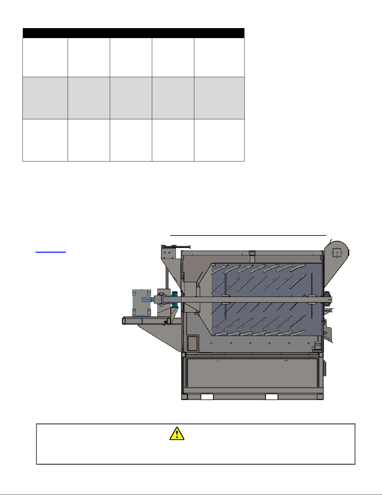
NOTE: In this manual, references of left and right-hand side are determined by facing the front of
roaster.
Side view cut away example of roaster body
Roaster: The upper
portion of the roaster
consists of a carbon steel
roasting drum with a unique
paddle arrangement supported
by bearings mounted at
each end and driven by
a heavy-duty gearbox
motor. The back of
the roasting drum has an
open center. This allows the
hot air to enter the roasting cylinder,
pass through the coffee mass and exit
the roasting cylinder through the
opening in the top front plate.
The lower section houses the burner(s)
and gas train components, heat shielding
from burners, air/grease lines, and the
roaster control panel (electrical junction box).
DANGER
Ensure the chaff is cool before emptying the chaff into any other containers. Hot
embers residing in the chaff could continue to heat and possibly ignite a fire.

Page 3 of 35
Chaff Collection Cyclone: The chaff collection cyclone(s) separate the coffee husk from the
exhaust air before it is expelled into the exhaust system. The cyclones are positioned at the rear
of the roaster and a detachable collection barrel is positioned under the cyclones to collect chaff.
The chaff collection barrel requires emptying periodically depending on the type of bean.
Cooling Bin: The cooling bin is the round piece of equipment located at the front of the roaster.
The cooling bin’s function is to contain the roasted coffee and cool it when it’s discharged from the
roasting drum.
The cooling bin consists of two levels. The upper level is called the cooling tray. The cooling tray
contains the agitator that levels the coffee as it exits the roasting drum. The agitator stirs the coffee
in the cooling bin and moves it to the outer area for discharging. The lower area contains the
agitator driveline that powers the agitator. The driveline consists of a drive shaft that is connected
to an electric motor. A special access door located on the side of the cooling bin exists for
accessing the agitator driveline.
Blower Housing: A blower motor and impeller are contained in the standard cooling bin blower
housing or attached to the cooling bin cyclone. The blower motor and impeller create the vacuum
necessary for moving the air that cools the coffee. The blower housing is connected to the cooling
bin by a removable (for cleaning) air duct that runs to the blower housing.
The coffee is quickly cooled by moving large amounts of room temperature air down through the
roasted coffee and by the mixing action of the agitator. The coffee must be kept moving for the
first several minutes while it is hot to stop the coffee from continuing to roast in the cooling tray.
The air along with any smoke from the hot coffee is then exhausted out the cooling bin ducting.
After the coffee is cooled, it can be discharged into storage containers through the discharge gate
on the cooling tray or into an optional destoner.
Optional Equipment
Loader: The loader’s function is to move the green coffee to the funnel located on top of the
roaster. The standard Diedrich loader consists of a motor and impeller assembly, a green bean
floor station, and a steel tube. The motor and impeller creates the vacuum required to lift the beans
from the green bean floor station through the tube to the green bean funnel located on top of the
roaster. After the roaster has been properly brought to operating temperature, the green coffee
can be released into the roasting drum.
Destoner: The function of the destoner is to separate and collect foreign objects that may be in
the roasted coffee (i.e., small stones). This process is done after the coffee has been roasted
since it is not as heavy as the green bean coffee. The roasted coffeeis vacuumed into an elevated
silo. Using gravity, the heavier objects fall into a collection area at the bottom of the roasted coffee
receiver. A slide gate is used to discharge the coffee from the silo.
DANGER
Always turn on the cooling bin agitator and blower prior to discharging the roasted
coffee into the cooling bin. Failure to do so could cause the coffee to continue to heat
and possibly start a fire.

Page 4 of 35
Oxidizer: The oxidizer is a burner system that significantly reduces theamountof smoke from the
roasterexhaust. Theoxidizerisbuiltofcarbonsteelwithastainless steel liner and vent connection.
The lower section houses the actual burner assembly.
The oxidizer is activated automatically when the coffee reaches 250°F (121°C). Shortly after this
temperature the coffee starts to emit fumes. When the oxidizer is activated, it quickly climbs to a
temperature where the smoke and odors are burned. It stays at an elevated temperature until the
coffee has cooled in the cooling tray and then the oxidizer burner returns to the lower temperature
for the next batch.
3.0
SITE PREPERATION
The customer is responsible to make arrangements for unloading and positioning their roasting
system.
When practical, install the vent ducting before receiving the roaster. Refer to your copy of the pre-
approved layout drawing for the exact location of the exhaust ducting. Final ducting connections
to the roasting system will occur when the system is in place and lagged to the floor. Mark out the
center lines of all components starting with the center line of the exhaust penetration through the
roof. Measure out and mark the center lines, intakes and exhaust locations of all components to
be installed.
The system will remove fresh air from the building. Normally an additional fresh air inlet is required
to allow for burner “make up air”. The size and type is dictated by local codes and often must be
installed prior to roasting. A licensed HVAC contractor should be utilized for the make-up air
requirements.
The environmental operating temperature ranges for the roaster should be as follows.
•Temperature range: 41°F to 104° F (+5 °C to +40 °C)
•Electrical equipment shall be capable of operating correctly when the relative humidity is
up to 50% at a maximum temperature of 104°F (+40 °C)
•Electrical equipment shall be capable of operating correctly at altitudes up to 3,280 feet
(1000 meters) above mean sea level.
•Electrical equipment designed to withstand the effects of transportation and storagewithin
a temperature range of -13°F to 131° F (-25°C to +55 °)
4.0 RECEIVING AND UNPACKING EQUIPMENT
When the roaster and its systems are received, immediately check the tilt sensor for crate damage.
Do not refuse shipment if damage is evident. Make notes of the damage on the appropriate
shipping forms and take several photos of the damage. Uncrate the components and inspect for
further damage, dents, or scratches. Immediately file a claim with the freight carrier if damage is
evident. A forklift can lift the roaster from the pallet at the fork tubes located on either the lower
right side of the roaster or the front of the roaster, depending on the size (see illustration, next
page).
Page 5 of 35
5.0 ROASTER INSTALLATION
It is the purchaser’s responsibility to ensure the appropriate codes and regulations, specific to their
area, arefollowed tomake sure that proper site engineering and installation requirements are met.
Clearances to combustible/non-combustible walls or counters must be considered. The roaster
and oxidizer should be located at least 36 inches (92 cm) from any surrounding walls. For ease of
access to the roaster and oxidizer, 48 inches (122 cm) is preferred. A sufficient area around the
roaster for safe movement of all personnel is required. The venting and ducting area between the
roaster and afterburner should have limited accessibility as this area contains extremely hot pipes.
Make sure all controls, access doors, and inspection panels are accessible and can open without
restriction.
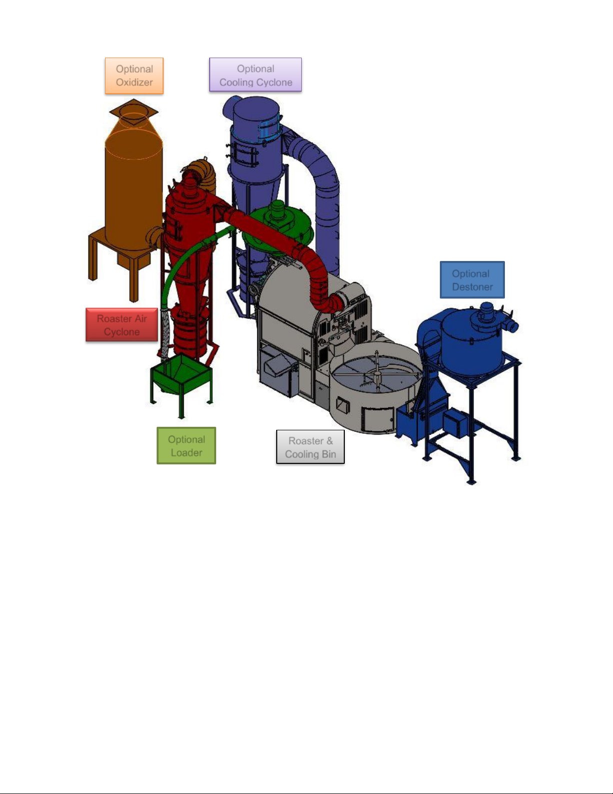
Assemble the roaster by working backwards from the exhaust point to the cooling bin. Assembling
the system in this manner reduces the number of possible misalignments.
Optional
Oxidizer
Optional
Cooling Cyclone
Optional
Loader
Optional
Destoner
Roaster &
Cooling Bin
Roaster Air
Cyclone
Page 6 of 35
6.0
ROASTER PARTS
6.1
DRUM RETAINING COLLAR
Drum Retaining Collar
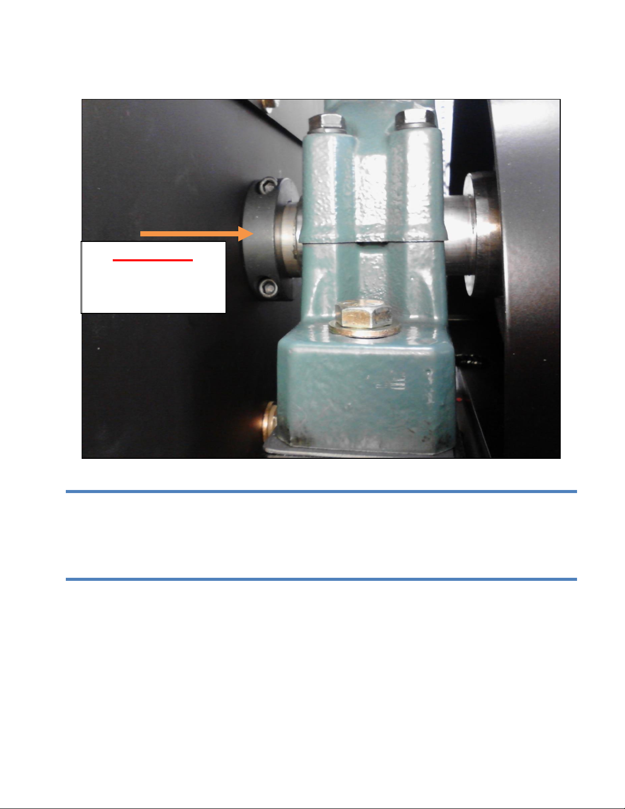
ATTENTION
A split collar is installed on the drum shaft to help prevent the drum from shifting during
shipment. The collar MUST beremoved before turning on the drum motor. The collar is located
at the rear of the roaster between the back plate and the bearing. There may also be a collar
mounted on the front bearing that needs to be removed.
6.2
CYCLONES AND BLOWERS
CR-70: Hang and bolt the roast air cyclone onto the frame at the back of the roaster. Install the
roast air pipe between the roast air hopper on the front of the roaster and the cyclone inlet with
the provided strap clamps. Place the cooling bin cyclone or cooling bin blower in position so the
outlet lines up with the exhaust stack or oxidizer inlet.
ATTENTION
Remove this split collar
before
turning on the
drum motor.

Page 7 of 35
CR-35, CR-140, and CR-280: Position the roast air cyclone so the outlet lines up with the exhaust
stack or oxidizer inlet. Place the cooling bin cyclone or cooling bin blower in position so the outlet
lines up with the exhaust stack or oxidizer inlet. (See layout drawing.)
6.3
ROASTING SECTION
The roasting section must be installed on a flat, non-combustible surface. If shims are required,
they must be non-combustible. The flooring must meet the weight bearing requirements of local
codes for commercial buildings.
The coffee roaster is designed to be raised by the fork tubes on the bottom of the roaster. Set the
roaster into position for proper alignment with the ducting connecting the cyclone.
Mount the green coffee loading funnel with the loader motor/blower installed onto the hopper at
the top rear of the roaster. Install the four (4) bolts with lock washers and tighten to the slide
gate/funnel support box. The funnel is heavy and is most easily lifted with a forklift with padding
on the forks. If the roaster is equipped with a green bean loader, the exhaust of the loader should
be ducted outside of the building.
Now the roaster canbeset into position. The ducting should be held in place between components
to ensure the proper fit before the roaster is secured in its final place. All venting sections are
connected using strap clamps. This allows the easy removal of sections for frequent cleaning.
Sections can be clamped together at one end when assembling components of the roasting
system to aid in the assembly process.
6.4
COOLING BIN INSTALLATION
The CR Series Roasters have a cooling bin which is placed in front of the roaster. The cooling bin
is designed to be raised from the lower front with a fork lift.
Slowly move the cooling bin toward the roaster, being careful to guide the cooler in and not pinch
or damage the air/grease lines and power cords with roaster frame. The front left of the cooling
bin has an access panel that will assist in connecting the lines / cords. The CR-140 and CR-280
CR-210, and CR-280 cooling bin ducting runs alongside the roaster, and the stainless bean
discharge chute on the front of the machine needs to be removed prior to cooling bin installation.
After placement, there are fork tube covers provided with your shipment to cover the fork tube
access points.
The cyclone frame or cooling blower can now be bolted to the floor in its proper position.
DANGER
Do NOT connect any of the utilities until the roasting system is in its final position.

Page 8 of 35
6.5
DESTONER SYSTEM (Optional)
The destoner is built in several sections to accommodate a range of installation options; the base
unit, the trunk and the silo with vacuum blower. If it is shipped disassembled, all flanges andtube
connections must be sealed with a silicone caulking to prevent vacuum leaks. If this is not done,
the system may be unable to create the vacuum needed to lift the coffee.
If the destoner silo is mounted to the building structure, the complete installation must be
engineered to accountfor the weight of the coffee, the silo and components. Another consideration
is the rigidity of the mounting structure, as the starting torque of the blower motor can cause
shifting if the installation structure is inadequate.
The exhaust of the destoner should be ducted outside the building and should allow access to
inspect and or clean as needed.
7.0
GAS INSTALLATION
The gas installation must conform to applicable codes established by local government and
regulatory officials. A licensed/certified gas technician should be used for the gas installation.
All pipe used for the installation must be at least Schedule 40 pipe. Sealant on pipe joints must be
resistant to liquid propane and natural gas. A water trap to collect condensation and loose particles
should be installed in the last vertical run upstream of the roaster. The gas piping for both the
coffee roaster and the oxidizer should be rigid gas pipe with the appropriate strain reliefs or
earthquake shut-off as required to meet local codes. All gas lines should be pressure tested and
bled prior to connecting to the roaster.
7.1
PIPE SIZING
Sizing of the gas supply line is critical for optimal performance. The supply line must have enough
gas volume to obtain the maximum BTU rating specified in the Capacities Chart per descriptions
on page 1 and still maintain the minimum pressure requirements. Ensure your gas technician or
the gas company sizes the gas supply line in accordance with the maximum BTU demands of the
roaster and any other appliances connected to the gas line. The pipe size and pressure supplied
will directly affect the performance of the roaster. Insufficient gas pressure or volume will resultin
poor performance of the roaster and the oxidizer may not reach sufficient temperatures.
7.2
SAFETY SHUT OFF VALVE
A safety shut-off valve must be installed in the gas supply line before the connection to the roaster
and in a location where it can be reached quickly in an emergency situation. The shut-off must be
located close to the machine and must be marked to identify it as the gas shut-off.

Page 9 of 35
7.3
INCOMING REGULATOR
ATTENTION
If the installation has both a roaster and oxidizer, a separate incoming pressure regulator must
be used for each piece of equipment.
An incoming regulator must be installed to adjust the incoming pressure to the roasters required
pressure as indicated in the Capacities table on page 1.
All connections must be tested prior to use of your equipment.
7.4
REGULATOR VENTING
The secondary gas pressure regulator supplied with the roaster must be vented to the building’s
exterior in accordance with local codes.
8.0 ELECTRICAL INSTALLATION
The electrical installation must conform to applicable codes established by local government and
regulatory officials. A licensed/certified electrician should be used for the electrical installation.
Please refer to the electrical conduit schedule provided separately for supply feed specifications
and wiring information. Use separate Low and high voltage conduits to reduce cross-
interference; low= communication wiring; high= power wiring.
The roaster and its related equipment must be wired together onsite. The installation must be
hard-wired (piped conduit) with grounding wires to the electrical source.
The main electrical panel must be installed such that the disconnect device is situated between
0.6 meters (~2ft.) and 1.9 meters (~6.3ft.) above the floor level.
All components in the roaster are electrically grounded to the roaster frame. All wiring in the
machine is labeled and color coded. The wires are also marked for their location on the terminal
strips and motor terminations refer to the “Electrical Conduit Schedule” that is supplied in the
electrical schematic documents . The loader and roast air blower motors are already wired in; they
just need to be reconnected at each motor’s electrical junction box during installation.
8.1
MANUAL ROASTERS
The optional destoner must have its own electrical circuit run to it.
CAUTION
To avoid a severe shock, all components must be grounded.

Page 10 of 35
8.2
AUTOMATED ROASTERS
All CR-Series roasters have a free standing electrical panel Main Control Panel (MCP) which is
mounted separately from the roaster. The incoming power is fed to the freestanding electrical
panel MCP. The optional destoner receives its power from the freestanding control panel circuit.
With the electrical control panel set into position, the conduit can be installed between the roaster
and the electrical control panel.
8.3
MOTOR ROTATION
Once the roaster has been wired and checked for safety, you must check the direction of motor
rotation to ensure it is correct.
9.0
WATER INSTALLATION
The water quench inlet pipe is located on the right rear of the roaster. See the separate supplied
“Installation Guide” for details on capacities and connection size.
A low-flow, 10 micron water filter on the incoming water line is recommended to prevent the
internal water nozzle from becoming clogged.
Installing an additional water hose is recommended, for cleaning and emergency situations.
9.1
SAFETY SHUT OFF VALVE
A safety shut-off valve must be installed in the water supply line before the connection to the
roaster and in a location where it can be reached quickly in an emergency situation. The shut-off
must be located close to the machine and should be marked to identify it as the water shut-off.
10.0
AIR COMPRESSOR INSTALLATION
Roasters equipped with a pneumatic slide gate system require an onsite air compressor. The air
inlet, pressure regulator and water trap are located at the rear of the roaster. The system requires
the pressures outlined in the Capacities Table located in the separate “Installation Guide.”
Installing an additional air hose with a blower nozzle is recommended for cleaning and
maintenance purposes.

Page 11 of 35
10.1
SAFETY SHUT OFF VALVE
A safety shut-off valve must be installed in the air supply line before the connection to the roaster
and in a location where it can be reached quickly in an emergency situation. The shut-off must be
located close to the machine and must be marked to identify it as the air supplyshut-off.
11.0 DUCTING
ATTENTION
Under no circumstances should Class B or Spiral-wrap ducting be used when exhausting hot
air.
WARNING!
The exhaust duct system is not to be supported by the Oxidizer or roaster.
The temperature of the ducting between the roaster, the cyclone and the afterburner typically runs
between 470oF to 500oF (243oC to 260oC). This area should be isolated so that it is not readily
accessible unless or until servicing of the vent system is required. Touching the hot vent pipe may
cause severe burns. Connections, flanges and clamps should be installed so they can be removed
easily for frequent cleaning. The vent system requires cleaning at regular intervals so easy access
must be considered.
One of the most important aspects of the roaster installation is the use of an approved ducting
system. Its design will greatly affect the performance of the coffee roaster and the coffeequality.
Two considerations when designing a ducting system are the static pressure and the distance the
ducting is to combustible/non-combustible materials.
All makes of Diedrich coffee roasters and oxidizers have a blower mounted inside which forces
exhaust air into the ducting. The oils and residues in the exhaust air are flammable. In the event
of a ducting/flue fire, the internal duct temperatures can exceed 1000°F (538°C), which could
cause nearby combustible materials to ignite. For this reason, Diedrich recommends at least
stainless-steel double wall positive pressure grease ducting.
Ducting must be suitable for 1000°F (538°C) continuous and 1400°F (760°C) intermittent
operating temperatures.
CR roasting systems have two separate ducting exhausts. There is one exhaust duct for the roast
air coming from the drum and one exhaust duct for the cooling bin air. The exhaust ducts are
typically joined into an oxidizer and one duct exits the oxidizer.

Page 12 of 35
It is highly recommended to also vent exhaust for optional loader and destoner. High
temperature vent pipe is not required. This will eliminate coffee debris blowing into your roasting
facility.
CR systems that do not use an oxidizer have two hot exhaust ducts leave the roaster and exit the
building (one for Roast Air and one for Cooler exhaust).
Exhaust pipe diameter must be at least the same diameter as the exhaust outlet on the equipment
(refer to equipment layout drawings).
The exhaust system must be designed to operate with a static flue pressure between positive
0.25”WC and negative 0.15”WC (positive .63 MBAR and negative .37 MBAR) at the exhaust
of the roaster while in operation.
Check local codes and regulations to determine the requirements specific to your location.
Designing an exhaust system requires a trained professional to calculate the efficiency of the
system and proper size of duct. The ducting must be of sufficient diameter to accommodate the
SCFM (standard cubic feet per minute) or SCMH (standard cubic meters per hour) of airflow. A
certified/licensed HVAC technician or one of the vent ducting companies listed below can assist
you with the best ducting layout for your site. Before calling them for assistance you will need to
be prepared to provide the technical information from the Capabilities Table on page 1.
When venting your roaster, a direct vertical run is typically the most efficient and cost-effective.
The design of your building may dictate the use of 45° or 90° elbows which will put a restriction on
the airflow and may cause unwanted backpressure on the roaster. If space allows, use two 45°
elbows rather than a 90° elbow to reduce restriction. A booster fan may be needed to assist air
movement if the system is too restrictive. A qualified ducting specialist will determine the best
design for your specific installation. The roaster must not support the weight of the exhaust system.
Ducting should be connected to the roaster based on the ducting manufacturer’s recommendation.
ATTENTION
Fires are caused by failure to maintain a clean roaster and its exhaust ducting system. Regular
cleaning of the roaster and exhaust ducting will help prevent the buildup of residues and
conditions that could cause fire.
A properly designed and installed chimney cap/rain cap is critical to the overall design. The
manufacturers listed on the next page offer components to prevent water penetration into the
system. Water leaking into an oxidizer may cause an electrical short or damage the burner
assemblies on the equipment. Some air quality jurisdictions dictate the use of certain types of
chimney caps/rain caps also. The cap must not have a screen since it will clog with residue of
chaff over time.
In order to provide our customers with a choice of venting options wehave included a list of several
ducting manufacturers as a starting point. This is just a list of companies who are familiar with
Diedrich roasters, other manufacturers may be used. Your HVAC specialist may have a
recommendation or preferred manufacturer. Some ducting manufacturers have on-siteengineers

Page 13 of 35
to assist you in designing your unique exhaust ducting. Please be advised, positive pressure
grease vent is not an off-the-shelf product, plan ahead to compensate for long lead times.
Recommended Ducting Manufacturers
Selkirk Metalbestos, Inc.
www.selkirkusa.com
Van-Packer
www.vpstack.com
Security Chimney International a division of LENNOX Hearth Products
www.lennoxhearthproducts.com
Jeremias
www.jeremiasinc.com

Page 14 of 35
OPERATION AND MAINTENANCE
12.0
SAFEGUARDS
The proper installation, cleaning, and safe operation of the coffee roasting system are the owner
and operator’s responsibility.
1)
Prior to cleaning or servicing ensure the circuit breaker in the electrical control box is
switched to the off position. Test for power prior to cleaning or servicing.
2)
Ensure the coffee roaster is cool to the touch prior to cleaning or servicing.
3)
Wear protective gloves and eyewear when scrapping residue off internal walls and
components.
4)
Use extreme caution when utilizing scrappers or other devices to clean internal walls and
components, a slip of a tool may cause bodily harm.
Read this manual carefully for important operation, maintenance and safety information. All
persons operating the Diedrich coffee roaster must be properly trained in the safe and proper use
of the roasting system. The safe use of this equipment also requires an understanding of the
basic chemistries that occur during the roasting process so that subtle warnings can be
identified before problems arise. Never permit an unqualified individual to operate this roaster.
A qualified operator must have a clear understanding of proper and intended use of the equipment,
roasting methods, cleaning requirements, fire suppression procedures and must be aware of all
safety precautions.
Operators must understand how to start and stop the motors using the control system. In
particular, the operator should be aware of the emergency stop button. This button disconnects
the control power and shuts off the motors and gas.
WARNING!
Never, under any circumstances, put a hand or any body part into the roasting drum, or any
other roaster access port, until the roaster has cooled down and power has been disconnected
at the electrical source.
WARNING!
Always make sure the chaff is cool before emptying the chaff into any other containers such
as a waste container. Hot embers residing in the chaff could ignite a fire.
WARNING!
Never leave the roaster unattended while it is turned on. Empty the chaff at the end of every
roasting session before leaving the roaster.

Page 15 of 35
Keeping the roasting system clean internally and externally cannot be over-emphasized. The
handling of coffee and the coffee bags creates dust and residues which are a fire hazard. Oil,
residues, and certain gases released during roasting are combustible. This residue collects on the
internal walls of the airflow passages and presents a significant fire hazard.
Fire extinguishers should be located within easy reach of the roasting system. These should
preferably be CO2extinguishers with sufficient capacity for a severe roasting system fire. Consult
with your local fire professional for recommendations on suitable fire extinguishers
Be careful when touching the roaster components, as some of these areas are very hot. The
motors, ducting, and chaff cyclone are extremely hot. This area should have restricted access and
not be entered until the system is cool and power has been disconnected.
Water Quench should be used to stop the aggressive exothermic reaction within a few degrees of
the final roast temperature, especially during darker roasts. Although water quench can be used
to cool the beans, it is not intended to be used for fire suppression or containment. Consult with
your local fire fighting professional for steps to take in case of fire.
ATTENTION
Improper installation and operation may result in a fire or explosion causing property damage,
personal injury or death. Adherence to these instructions is imperative.
CAUTION
Always be aware of the risk of a fire. Fires are caused by failure to maintain a clean
roaster and the exhaust duct system. A dirty roaster will also affect the efficiency of the
roasting system. More importantly the balance of the heat media will be compromised,
changing the cup quality of the coffee.
CAUTION
Roasted coffee emits a significant amount of CO (carbon monoxide) gas. Inhalation of
this gas can prove fatal. When entering any roasted coffee silo or container, the silo or
container must be well ventilated and an observer must be present during this time.

Page 16 of 35
DO NOT store or use gasoline or other flammable liquids in the vicinity of this roaster or any other
appliances.
IF YOU SMELL GAS:
•Evacuate the building to a safe distance.
•Do not try to light any appliance.
•Do not touch any electrical switch.
•Do not use any phone in your building.
•Immediately call your gas supplier from a nearby phone.
•Follow the gas supplier’s instructions.
•If you cannot reach your gas supplier dial 9-1-1 or call the Fire Department.
If this roaster is not installed, operated and maintained in accordance with this manual, youcould
beexposed to substances in fuel orfrom fuel combustion which can cause serious illness ordeath.
This manual suits for next models
4
Table of contents
Other Diedrich Roasters Kitchen Appliance manuals


Popular Kitchen Appliance manuals by other brands


Victorio
Victorio Poppy VKP1163 instruction manual

Kasanova
Kasanova MULTI CUOCO instruction manual

Nouvel
Nouvel Sous Vide Complete-Set Instructions for use

Blomberg
Blomberg WSN 1412 LT Instructions for use

Amica
Amica WKR 341 910 R operating instructions

Vollrath
Vollrath Cheese Blocker 1837 Operator's manual


