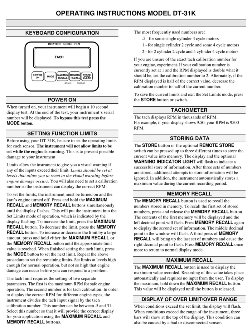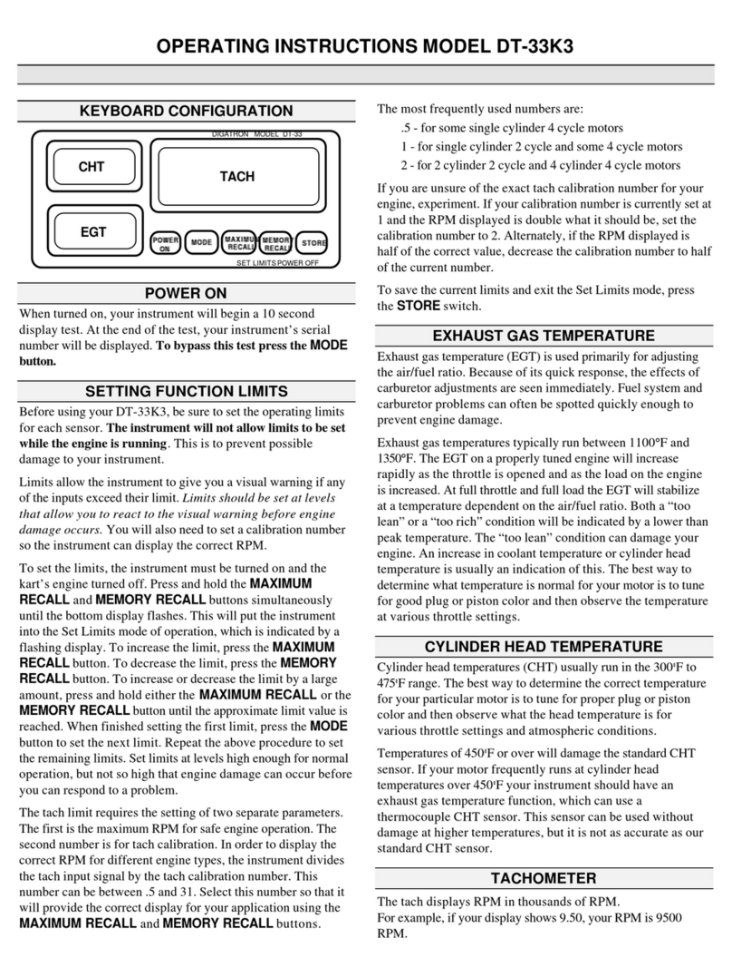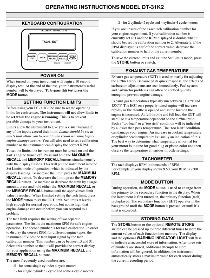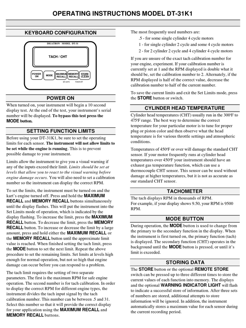
After drilling and deburring the 1/2" hole in the dash panel,
place the aluminum indicator bezel through the hole from the
driver compartment. Press the retaining washer on to the back
side of the aluminum bezel. (Takes a lot of pressure.) Insert the
lamp assembly through the back of the bezel into the lens.
Press the plastic retaining plug into the rear of the bezel to se-
cure the lamp assembly in place. Connect the lead to the Or-
ange connector on the back of the instrument. Twist the con-
nector 1/4 turn to lock it in place.
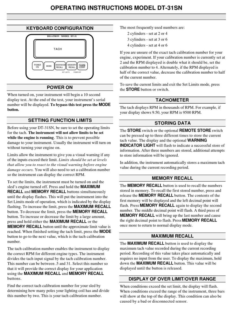
EXHAUST TEMPERATURE SENSORS
P/N EXT-1 *** RBN Because the EGT sensor leads are
the most sensitive to ignition interference or electrical interfer-
ence, it is recommended that the probes be installed in the rear
header tubes of a front engine vehicle and in the front header
tubes of a rear engine vehicle. Installed in this manner it will be
easier to route the leads to maintain the recommended distance
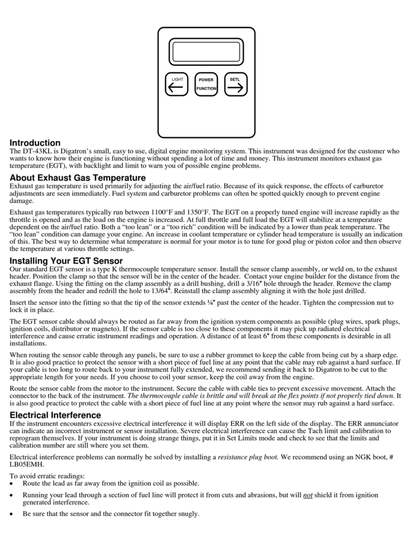
from ignition components. Install the sensor into the header at
a point approximately 2" from the head side of the exhaust
flange. Drill a 13/64" hole in a location in the header which will
allow easy access to the sensor. Install the exhaust clamp as-
sembly on the header aligning the compression fitting base
with the drilled hole in the header. The tip of the sensor should
be located at a point approximately 1/4" past the center of the
header. Tighten the compression fitting nut to secure the sen-
sor in place. Tighten the clamp assembly to secure it to the
exhaust header. Route the sensor wires to the instrument pay-
ing particular attention to the routing precautions outlined
earlier. All exhaust temperature sensors use the same color
boot on their connectors. You may want to use a permanent
marking pen on the boot to code the leads from the engine
Connect the sensors to the Gray terminals on the back of
the instrument. The placement of the terminals on the instru-
ment corresponds with the window that EGT is displayed in..
Twist the connector 1/4 turn to lock it in place.
The long black wire near the sensor probe must then be at-
tached to a convenient ground point on the engine. This wire
is covered with a high temperature Teflon that can withstand a
good deal of heat but should not rest on top of the header
pipes.
Repeat this process for any remaining exhaust sensor(s).
NOTE: The Exhaust Temperature Sensor leads are the
most susceptible to electrical interference. In extreme circum-
stances where electrical interference cannot be eliminated by
following the outlined procedures, try the following sugges-
tions. Route your Exhaust Temperature Sensor leads through
a grounded metal tube to the instrument.
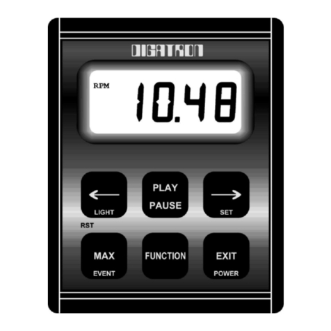
REMOTE STORE SWITCH
P/N SA-CBN The Remote Store Switch should be
mounted in a steering wheel spoke within thumbs reach of the
driver. This switch requires a 15/32" mounting hole for installa-
tion. If a steering wheel spoke is not available to accommodate
the switch, a bracket must be fabricated for mounting. Mount
the bracket to the steering wheel in a position that will provide
easy access to the switch while driving.
Tie the coil cord to the steering wheel and or column where
needed to prevent it from interfering with the driver. Connect
the lead to the White connector on the back of the instrument.
Twist the connector 1/4 turn to lock it in place.
OIL TEMPERATURE SENSOR
P/N 0T-1 *** BN Any port normally used to monitor
the oil temperature may be used for the Oil Temperature Sen-
sor. The compression fitting supplied with the sensor is a
standard 1/8" Iron pipe thread. Insert the end of the sensor
through the compression fitting into the oil to a depth of at
least 1". Tighten the compression nut to secure the sensor in
place.
Route the sensor wire to the instrument, paying attention
to the above wire routing notes. Attach the lead to the Yellow
connector on the rear of the instrument. Twist the connector
1/4 turn to lock it in place.
In some installations, a reducing bushing may be required
to adapt the compression fitting to an available oil temperature
port.
WATER TEMPERATURE SENSOR
P/N WT-1 *** BN The location of the Water Tempera-
ture Sensor should be well below the water level in the engine
block or in a location provided in the engine for the purpose of
monitoring water temperatures. Do not use the radiator for
monitoring water temperature readings. The water temperature
sensors use the same compression fitting as the oil tempera-
ture sensor.
Route the sensor wire to the instrument, paying attention
to the above wire routing notes. Attach the lead to the Red
connector on the rear of the instrument. Twist the connector
1/4 turn to lock it in place.
In some installations, a reducing bushing may be required
to adapt the compression fitting to an available water tempera-
ture port.
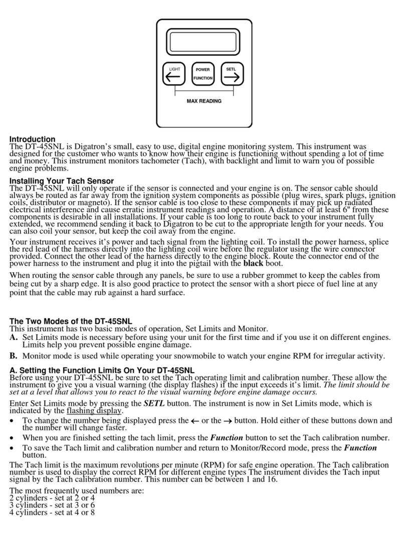
TACH SENSOR INSTALLATION NOTE
If this instrument has a Tach function included as a stan-
dard feature, the tach sensor must be connected to the ignition
system to provide a tach signal to the instrument. If this lead is
not used the instrument will automatically turn itself off after a
period of approximately 10 minutes.
Digatron builds three general types of Tach Sensors de-
signed for different types of ignition systems. A sensor de-
signed for a CDI type ignition will not work on a vehicle with a
magneto. If you change to another type of ignition system, do
not connect the old tach sensorto this new system. SERIOUS
instrument damage may result from using the wrong Tach Sen-
sor.


