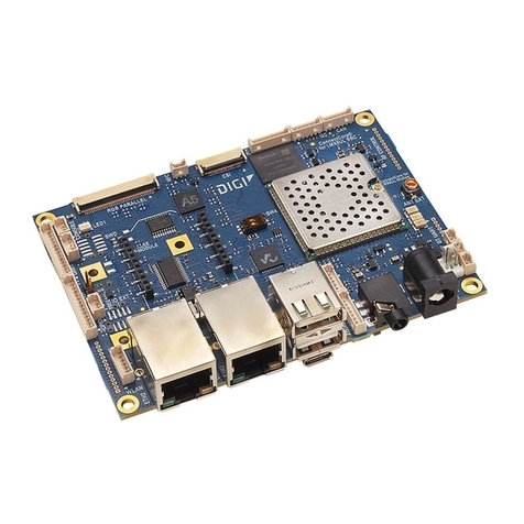
Digi ConnectCore 8X Quick user guide

ConnectCore 8X
SBC Express
Hardware Reference Manual -- Preliminary

Revision history—90002296
Revision Date Description
1P December 2018 Initial release
2P October 2019 Added XBee socket note.
Trademarks and copyright
Digi, Digi International, and the Digi logo are trademarks or registered trademarks in the United
States and other countries worldwide. All other trademarks mentioned in this document are the
property of their respective owners.
© 2019 Digi International Inc. All rights reserved.
Disclaimers
Information in this document is subject to change without notice and does not represent a
commitment on the part of Digi International. Digi provides this document “as is,” without warranty of
any kind, expressed or implied, including, but not limited to, the implied warranties of fitness or
merchantability for a particular purpose. Digi may make improvements and/or changes in this manual
or in the product(s) and/or the program(s) described in this manual at any time.
Warranty
To view product warranty information, go to the following website:
www.digi.com/howtobuy/terms
Customer support
Gather support information: Before contacting Digi technical support for help, gather the following
information:
Product name and model
Product serial number (s)
Firmware version
Operating system/browser (if applicable)
Logs (from time of reported issue)
Trace (if possible)
Description of issue
Steps to reproduce
Contact Digi technical support: Digi offers multiple technical support plans and service packages.
Contact us at +1 952.912.3444 or visit us at www.digi.com/support.
ConnectCore® 8X SBC Express Hardware Reference Manual -- Preliminary 2

ConnectCore® 8X SBC Express Hardware Reference Manual -- Preliminary 3
Feedback
To provide feedback on this document, email your comments to
techcomm@digi.com
Include the document title and part number (ConnectCore® 8X SBC Express Hardware Reference
Manual -- Preliminary, 90002296 2P) in the subject line of your email.
Contents
About the ConnectCore 8X SBC Express
Features and functionality 4
Block diagram 6
Interfaces
Connectors, jumpers, and switches 8
Top view 8
Bottom view 9
Description 9
Input power connector 10
Coin cell connector 10
Boot mode 10
Power and reset buttons 11
SWD 12
Console port 12
microSD 13
10/100Mbps Ethernet 13
LVDS/MIPI-DSI display 13
LVDS 14
MIPI-DSI 15
Touch controller 16
USB host 16
XBee 17
Expansion connector 18
USB device 21
User LED and button 21

About the ConnectCore 8X SBC Express
The ConnectCore 8X SBC Express is an ultra-compact board featuring the Digi ConnectCore 8X
system-on-module (SoM). The ConnectCore 8X system-on-module integratesan NXP i.MX 8X
application processor with LPDDR4 and eMMC flash memory, WLAN/Bluetooth, power management IC
for optimized power consumption applications, and a Microcontroller AssistTM (MCA) for additional
functionality.
This standalone product serves as the reference design for the ConnectCore 8X system-on-module
and can also be used on its own to accelerate time to market.
Features and functionality
nConnectCore 8X System-on-module
li.MX 8X Dual/Quad ARM Cortex-A35 and single Cortex-M4F cores.
l2 GB, 32-bit LPDDR4-1200 memory.
l8 GB, 8-bit eMMC memory.
lIEEE802.11 a/b/g/n/ac and Bluetooth 4.2.
n5V DC-in power jack connector.
nBoot source configuration: internal eMMC, microSD, USB.
nCoin-cell connector to supply the on-module real-time clock (not populated by default).
nPower and reset buttons.
nDebug:
lSingle Wired Debug (SWD) interface for the Microcontroller AssistTM (MCA).
lTTL Serial console.
nStorage:
lmicroSD card.
nCommunication:
l10/100 Mbps Ethernet interface.
lTwo USB Host 2.0 with stacked USB A-type connectors.
lUSB device with micro AB USB connector (shared with one USB host port).
lXBee socket supporting XBee Cellular (USB bus shared with one of the USB host port).
nExpansion
lExpansion connector that can accommodate Raspberry PI Hat boards.
lAdditional expansion header row, not populated by default.
ConnectCore® 8X SBC Express Hardware Reference Manual -- Preliminary 4

About the ConnectCore 8X SBC Express Features and functionality
ConnectCore® 8X SBC Express Hardware Reference Manual -- Preliminary 5
nUser interface:
lx1 User LED.
lx1 User button.
nDimensions:
l87 x 63 mm

About the ConnectCore 8X SBC Express Block diagram
ConnectCore® 8X SBC Express Hardware Reference Manual -- Preliminary 6
Block diagram

Interfaces Block diagram
ConnectCore® 8X SBC Express Hardware Reference Manual -- Preliminary 7
Interfaces
Connectors, jumpers, and switches 8
Top view 8
Bottom view 9
Description 9
Input power connector 10
Coin cell connector 10
Boot mode 10
Power and reset buttons 11
SWD 12
Console port 12
microSD 13
10/100Mbps Ethernet 13
LVDS/MIPI-DSI display 13
Touch controller 16
USB host 16
XBee 17
Expansion connector 18
User LED and button 21

Interfaces Connectors, jumpers, and switches
ConnectCore® 8X SBC Express Hardware Reference Manual -- Preliminary 8
Connectors, jumpers, and switches
Top view

Interfaces Bottom view
ConnectCore® 8X SBC Express Hardware Reference Manual -- Preliminary 9
Bottom view
Description
Connector Interface Manufacturer Manufacturer part number
J4 Coin cell Molex 53047-0210
J5 Console Molex 53047-0410
J6 Ethernet XMultiple XMG-9799-8821-100D-L1TO-H-
HIM
J7 LVDS Hirose DF14A-20P-1.25H
J8 MIPI-DSI FCI SFW15S-2STE1LF
J9 USB Host KYCON KUSBX-AS2N
J10 USB OTG KYCON KMMX-ABSMT5SG-30TR
J11 Expansion header Wurth
Electronics
61304021121

Interfaces Input power connector
ConnectCore® 8X SBC Express Hardware Reference Manual -- Preliminary 10
Connector Interface Manufacturer Manufacturer part number
J12-J13 XBee module Samtec SQT-110-01-F-S
J14 3V3_EXT Samtec TSW-102-07-G-S
J15 VIN Samtec TSW-102-07-G-S
J16 VCC_MCA Samtec TSW-102-07-G-S
J18 Touch controller Sullins GBC05SBSN-M89
J19 MCA SWD (not populated by
default)
Samtec FTSH-105-01-F-DV
Input power connector
A 5V DC-in power jack connector (J2) provides power to the ConnectCore 8X SBC Express system.
From this 5V power supply, a 3.3V LDO generates the power supply for the on-module MCA.
Coin cell connector
A 2-pin, 1.25 mm pitch straight connector (J4), not populated by default, can be used to connect an
external coin cell battery or supercap for powering the system's real-time clock (RTC) when the main
power supply is removed.
The RTC can be powered with a primary Lithium cell (non-rechargeable), a secondary Lithium cell
(rechargeable) or a supercap.
The following table shows the pinout of the coin cell connector:
Pin Signal name Description
1 VCC_LICELL Power supply for RTC
2 GND
Boot mode
By default, the ConnectCore 8X system-on-module boots from the internal board settings, allowing it
to boot from the internal eMMC flash memory. For advanced functionality, the ConnectCore 8X SBC
Express provides two switches (S3) to configure the SoM boot mode:

Interfaces Power and reset buttons
ConnectCore® 8X SBC Express Hardware Reference Manual -- Preliminary 11
Switch 2 Switch 1 Boot mode
Open Open eMMC
Open Closed Fuses
Closed Open microSD
Closed Closed Serial downloader
Serial downloader mode allows the system to boot from USB, which is ideal for recovery purposes,
such as if the boot loader is erased or cannot boot.
For more information about the boot mode configuration, see the ConnectCore 8X System-on-Module
Hardware Reference Manual.
Power and reset buttons
The power button (SW1) on the ConnectCore 8X SBC Express is connected to the on-module MCA,
which provides the following functionality:
Board status Power button action Response
OFF Short press Power on
ON or SLEEP Long press for 5 seconds Power off
SLEEP Short press Wake up
ON Short press Sleep

Interfaces SWD
ConnectCore® 8X SBC Express Hardware Reference Manual -- Preliminary 12
You can also reset the ConnectCore 8X system-on-module by pressing the Reset button (SW2) on
theConnectCore 8X SBC Express.
Note You can configure the duration of some power button actions. See the software documentation
for more information.
SWD
The ConnectCore 8X SBC Express provides two options for programming and debugging the
Microcontroller Assist of the ConnectCore 8X system-on-module.
nThe first option is a 2x5, 1.27 mm pitch pin header footprint on the top side of the board that,
by default, is not populated. The following table shows the pinout of the SWD connector:
Pin Signal name Description
1 VCC_MCA 3.3V supply voltage of the MCA
2 SWD_DIO/MCA_IO21 SWD bidirectional data pin
3 GND
4 SWD_CLK/PWR_IO SWD clock signal
5 GND
6 NC
7 NC
8 NC
9 GND
10 SYS_RESET Reset signal for MCA
nThe second option is the ARM 10-pin standard-compliant Tag Connect footprint on the bottom
side of the board.
Console port
The ConnectCore 8X SBC Express provides a 4-pin, 1.25 mm pitch connector (J5) as its debug console
port. The UART2 port of the ConnectCore 8X system-on-module is used for this purpose. The console
signal is a serial TTL, which travels through the console connector directly to the i.MX 8X processor. A
TTL-to-USB cable can be used for accessing this console port from a host PC USB port.
The following table shows the pinout of this console connector:

Interfaces microSD
ConnectCore® 8X SBC Express Hardware Reference Manual -- Preliminary 13
Pin Schematic signal name Description
1 CONSOLE_TX Transmission line
2 CONSOLE_RX Receiver line
3 3V3_EXT Output 3.3V power supply line
4 GND
Console default settings:
nBaud rate: 115200
nData: 8 bit
nParity: none
nStop:1 bit
nFlow control: none
microSD
A microSD socket (J3) is located on the bottom side of the board. This interface is connected to the
USDHC1 controller of the i.MX 8X processor.
10/100Mbps Ethernet
The ConnectCore 8X SBC Express provides one 10Base-T/100-Base-Tx Ethernet interface which uses
the Microchip LAN8720Ai 10/100 Ethernet PHY. The board includes an RJ-45 connector (J6) with
integrated link/activity LEDs.
The following table shows the link/activity status indicated by the two LEDs:
Green LED Yellow LED Link/activity status
OFF OFF Link OFF
ON OFF 10 Link/no activity
Blinking OFF 10 Link/activity
ON ON 100 Link/no activity
Blinking ON 100 Link/activity
The Ethernet PHY can be manually disabled through a power switch. The dedicated CPU GPIO used for
this purpose is GPIO5_IO8 (ENET0_PWR signal). By asserting this line low, the Ethernet PHY power will
be removed.
LVDS/MIPI-DSI display
One of the two MIPI-DSI/LVDS combo PHYs supported by the ConnectCore 8X system-on-module is
available over two different display connectors on the ConnectCore 8X SBC Express board:

Interfaces LVDS/MIPI-DSI display
ConnectCore® 8X SBC Express Hardware Reference Manual -- Preliminary 14
nOne LVDS connector (J7), located on the bottom side of the board.
nOne MIPI connector (J8), located on the top side of the board, which is not populated by
default.
Both connectors offers access to the same MIPI_DSI0 bus of the CPU, which can be configured to
work as MIPI or LVDS. Therefore, only one of the display connectors can be used at any given time.
LVDS
The LVDS interface is available over a 20-pin, 1.25 mm pitch connector, which provides access to the
following LVDS capabilities:
nUp to four LVDS differential data pairs.
nOne LVDS differential clock pair.
nInterrupt signal with 10K pull-up resistor for touch screen.
nControl of the backlight contrast.
nI2C, shared with the MIPI-DSI connector.
n3.3V power supply.
n5V power supply.
The following table describes the pinout of the LVDS connector:
Pin
Schematic signal
name Description
1 3V3_EXT Output 3.3V power supply line
2 MIPI_DSI0_DATA0_N Transmission pair 0 data line (-)
3 MIPI_DSI0_DATA0_P Transmission pair 0 data line (+)
4 GND
5 MIPI_DSI0_DATA1_N Transmission pair 1 data line (-)
6 MIPI_DSI0_DATA1_P Transmission pair 1 data line (+)
7 GND
8 MIPI_DSI0_DATA2_N Transmission pair 2 data line (-)
9 MIPI_DSI0_DATA2_P Transmission pair 2 data line (+)
10 GND
11 MIPI_DSI0_CLK_N Transmission pair clock line (-)
12 MIPI_DSI0_CLK_P Transmission pair clock line (+)
13 GND
14 MIPI_DSI0_DATA3_N Transmission pair 3 data line (-)
15 MIPI_DSI0_DATA3_P Transmission pair 3 data line (+)

Interfaces LVDS/MIPI-DSI display
ConnectCore® 8X SBC Express Hardware Reference Manual -- Preliminary 15
Pin
Schematic signal
name Description
16 MIPI_DSI0_PWM0_
OUT
Backlight PWM, connected to MIPI_DSI0_GPIO0_00 ConnectCore 8X
pad
17 MIPI_DSI0_I2C0_SCL I2C bus clock line
18 MIPI_DSI0_I2C0_SDA I2C bus data line
19 MIPI_DSI0_IRQ_N Interrupt line, connected to ConnectCore 8X GPIO4_19
20 VIN Output 5V power supply line
MIPI-DSI
The MIPI-DSI interface is available over a 15-pin, 1 mm pitch, FCC connector, which provides access to
the following MIPI capabilities:
nTwo MIPI-DSI differential data pairs.
nOne MIPI-DSI differential clock pair.
nI2C, shared with the LVDS connector.
n3.3V power supply.
The following table describes the pinout of the MIPI-DSI connector:
Pin Schematic signal name Description
1 3V3_EXT Output 3.3V power supply line
2 3V3_EXT Output 3.3V power supply line
3 GND
4 MIPI_DSI0_I2C0_SDA I2C bus data line
5 MIPI_DSI0_I2C0_SCL I2C bus clock line
6 GND
7 MIPI_DSI0_DATA0_P Transmission pair 0 data line (+)
8 MIPI_DSI0_DATA0_N Transmission pair 0 data line (-)
9 GND
10 MIPI_DSI0_CLK_P Transmission pair clock line (+)
11 MIPI_DSI0_CLK_N Transmission pair clock line (-)
12 GND
13 MIPI_DSI0_DATA1_P Transmission pair 1 data line (+)
14 MIPI_DSI0_DATA1_N Transmission pair 1 data line (-)
15 GND

Interfaces Touch controller
ConnectCore® 8X SBC Express Hardware Reference Manual -- Preliminary 16
Touch controller
One 5-pin, 2.54 mm pitch header (J18) is located in the bottom side of the ConnectCore 8X SBC
Express. This connectors outputs the I2C bus used for supporting the touch controller of the display,
which is also available in each display connector as described in the previous sections.
The following table shows the pinout of the expansion connector:
Pin Schematic signal name Description
1 VIN Output 3.3V power supply line
2 MIPI_DSI0_IRQ_N Touch controller interrupt line
3 MIPI_DSI0_I2C0_SDA I2C bus data line
4 MIPI_DSI0_I2C0_SCL I2C bus clock line
5 GND i.MX 8X I2C2 bus clock line
USB host
A stackable dual USB A-type connector (J9) is located on the top side of the ConnectCore 8X SBC
Express board to allow accessing the two USB 2.0 buses of the CPU. Both USB buses can operate at
low, full, and high speed.

Interfaces XBee
ConnectCore® 8X SBC Express Hardware Reference Manual -- Preliminary 17
XBee
The ConnectCore 8X SBC Express provides an XBee socket to connect a Digi XBee/XBee-PRO module. The XBee socket consist of two 10-pin, 2 mm pitch
connectors (J12 and J13) which follow the standard pinout of the XBee modules:
Description
Schematic
signal name
J12
pin XBee Standard pin
J13
pin
Schematic signal
name Description
Output 3.3V power supply line XBEE_VCC 1 1 - VCC ADC0/DIO0 - 20 1 -
XBee UART output data line XBEE_UART_RX 2 2 - DOUT AD1/DIO1 - 19 2 -
XBee UART input data line XBEE_UART_TX 3 3 - DIN/CONFIG_N AD2/DIO2 - 18 3 -
- 4 4 - D08 AD3/DIO3 - 17 4 -
XBee reset line, connected to
ConnectCore 8X GPIO3_13
XBEE_RESET 5 5 - RESET_N RTS_N/DIO6 - 16 5 XBEE_UART_RTC XBee UART
clear to send
line
- 6 6 - PWM0/RSSI AD5/DIO5 - 15 6 -
- 7 7 - Reserved VREF - 14 7 -
- 8 8 - Reserved ON/SLEEP_N - 13 8XBEE_ON/SLP_N XBee status
line,
connected to
ConnectCore
8X GPIO3_14
XBee request line, connected to
ConnectCore 8X GPIO3_16
XBEE_SLEEP_RQ 9 9 - DTR_N/SLEEP_
RQ/DI8
CTS_N/DIO7 - 12 9 XBEE_UART_CTS XBee UART
request to
send line
GND 10 10 - GND AD4/DIO4 - 11 10 -
The XBee can communicate with the ConnectCore 8X system-on-module in two different ways:

Interfaces Expansion connector
ConnectCore® 8X SBC Express Hardware Reference Manual -- Preliminary 18
nUsing the UART0 bus of the i.MX 8X CPU.
nUsing the USB_OTG2 bus.
The lines of these two communication buses are connected through 0-ohm resistors. By default, UART0 is connected (R62 and R63 populated) while USB_
OTG2 is not (R52 and R53 not populated).
CAUTION! The CPU USB bus connected to the XBee socket is the USB_OTG2, which is also connected to the dual USB A-type receptacle.
Connecting two devices to the USB_OTG2 port at the same time will cause a short circuit in the differential data pair.
CAUTION! The XBee socket is powered through an external DC/DC regulator(U23 - MP2316). The purpose of this external regulator is to provide
higher current than using 3V3 supply coming from the module. Disabling this regulator doesn't guarantee that the XBee socket is fully
disconnected from the module. In fact, some current travels through the I/Os to the module even after the regulator is disabled.
If your design requires fully disconnecting the XBee socket from the ConnectCore 8Xmodule, Digi recommends you use bus switches for all I/Os
connected to the XBee socket.
Expansion connector
A 2-row, 40-pin, 2.54 mm pitch header (J11) is supported by the ConnectCore 8X SBC Express board. This header acts as an expansion connector that
mimics the Raspberry Pi HAT connector specification, offering access to many different interfaces of the CPU.
The following table shows the pinout of the expansion connector:
Pin Schematic signal name Description
1 3V3_EXT Output 3.3V power supply line
2 VIN Output 5V power supply line
3 I2C2_SDA i.MX 8X I2C2 bus data line
4 VIN Output 5V power supply line

Interfaces Expansion connector
ConnectCore® 8X SBC Express Hardware Reference Manual -- Preliminary 19
Pin Schematic signal name Description
5 I2C2_SCL i.MX 8X I2C2 bus clock line
6 GND
7 GPIO1_17 i.MX 8X GPIO
8 EXPANSION_UART_TX See note below
9 GND
10 EXPANSION_UART_RX See note below
11 GPIO1_18 i.MX 8X GPIO
12 MCA_IO6 MCA GPIO
13 GPIO1_20 i.MX 8X GPIO
14 GND
15 GPIO1_28 i.MX 8X GPIO
16 GPIO1_29 i.MX 8X GPIO
17 3V3_EXT Output 3.3V power supply line
18 GPIO1_30 i.MX 8X GPIO
19 SPI3_SDO i.MX 8X SPI3 SDO line
20 GND
21 SPI3_SDI i.MX 8X SPI3 SDI line
22 GPIO3_15 i.MX 8X GPIO
23 SPI3_SCK i.MX 8X SPI3 SCK line
24 SPI3_CS0 i.MX 8X SPI3 CS0 line
25 GND

Interfaces Expansion connector
ConnectCore® 8X SBC Express Hardware Reference Manual -- Preliminary 20
Pin Schematic signal name Description
26 GPIO4_20 i.MX 8X GPIO
27 I2C3_SDA i.MX 8X I2C3 bus data line
28 I2C3_SCL i.MX 8X I2C3 bus clock line
29 GPIO4_21 i.MX 8X GPIO
30 GND
31 GPIO4_22 i.MX 8X GPIO
32 GPIO5_03 i.MX 8X GPIO
33 MCA_IO5 MCA GPIO
34 GND
35 MCA_IO7 MCA GPIO
36 MCA_IO8 MCA GPIO
37 MCA_IO3 MCA GPIO
38 MCA_IO4 MCA GPIO
39 GND
40 GPIO1_19 i.MX 8X GPIO
Note The UART bus connected to the expansion header of the ConnectCore 8X SBC Express board can be one of the following:
ni.MX 8X UART3.
nXBee UART, which is connected to the i.MX 8X UART0 bus.
The lines of these two communication buses are connected through 0-ohm resistors. By default, UART3 is connected (R64 and R65 populated) and UART0
is not connected (R66 and R67 not populated).
Other manuals for ConnectCore 8X
4
Table of contents
Other Digi Computer Hardware manuals

Digi
Digi ConnectPort X3 H User manual

Digi
Digi Errata NS9750B-A1 User manual

Digi
Digi Digi One EM Quick user guide

Digi
Digi Rabbit 5000 User manual

Digi
Digi NS9215 Application guide

Digi
Digi SYNC/570i User manual

Digi
Digi ConnectCore 9P 9215 User manual

Digi
Digi DigiBoard PC/ i Series User manual
Digi
Digi Digi JumpStart Kit User manual
Digi
Digi ConnectCore 9C Application guide