Digiflex CM743 How to use

Installer
Reference Guide
CM743
2G Radio Module
Rev 1.6
®
N12138N12138 RoHS

Page 2 P/N: CM743IRG Rev 1.6 E&OE Copyright © 2014
Introduction
The CM743 2G radio module allows you to interface
compatible security control panels to the GSM/GPRS /
SMS network providing a high reliability primary or
backup reporting path.
The unit is designed to plug onto the main control panel
with the supplied antenna mounting onto the metal
cabinet.
Module Compatibility
Panels Supported Version
Vision-X 2.12
Getting Started
There are four main steps required to configure the
CM743 for reporting to the control room. The instruc-
tions assume that you already have purchased a SIM
card and that the card has been charged with credit and
activated on the network if necessary.
1. Install the CM743 hardware on the control panel.
2. Install the antenna.
3. Configure the module’s features and parameters.
4. Configure the control panel for reporting.
Step 1 - Installing the Radio Module
Ensure that the panel is powered off before proceeding.
Plug the 3 short plastic standoffs into the module and
then plug it onto the Expansion Port header pins on the
panel as shown in. If you are connecting the CM743 to a
panel which also has a CM101 Voice Module fitted then
you should use the longer standoffs from the HW750
Riser Kit.
Install the SIM card into the SIM 1 card position.
Step 2 - Installing the Antenna
Remove the knockout in the top of the cabinet and pass
the antenna lead through the hole ensuring the antenna
is on the outside of the cabinet. Screw the lead to the
socket on the radio module before power the panel.
Do not fix the antenna in place at this stage.
Step 3 - Configuring The Module
Once powered the radio will attempt to connect to the
network. This may take up to a minute to complete.
During this time the online indicator on the module will
be on solid. Once the radio has registered the online in-
dicator will begin to flash and the signal strength indica-
tors will show the current signal condition.
Experiment with the position of the antenna to find the
best signal strength before fixing it in place.
Step 4 - Configuring The Panel Reporting
Reporting configuration will vary depending on the
required options and whether or not the GSM module is
to be used as the primary or secondary reporting route.
Configure the required reporting formats in MENU 5-4-0
and 5-4-1. The system can be configured to report to
the base in CID and also to selected phone numbers via
SMS, or to the base in CID via PSTN line and then CID via
GSM if the PSTN line is cut.
All reporting scenarios are configured by varying the
programming of the reporting format and reporting
routes configurations options.
Module Indicators
The module includes 7 led indicators which are used to
show status and signal strength. See table below.
Module Indicators
Indicator Meaning
TX Module Transmitting Data (Tx Data In CID)
RX Module Receiving Data (Kiss Off In CID)
Online ON Steady = Not Registered On Network
Pulsing = Registered On Network
Signal 1 Signal strength indicators show relative
signal level at the radio. Signal indicator 1
on indicates weak signal and all 4 indicators
on indicates stronger signal strength.
Signal 2
Signal 3
Signal 4
CM743 2G Radio Module

P/N: CM743IRG Rev 1.6 Page 3
Copyright © 2014 E&OE
CLI Triggers
The CLI trigger tables in MENU 6-5-5-1 and 6-5-6-2 can
be used to store a list of telephone numbers that can
trigger an output on the control panel. If you call the
GSM unit from a telephone number that matches a num-
ber in the CLI list then the appropriate output will be
operated.
An output needs to be programmed with an event type
of CLI Trigger and event assignment of 1 or 2 depending
on which table is to be checked.
Simply call the GSM unit from a telephone number that
is programmed in the CLI trigger list to activate the
output.
Module Status
MENU 6-5-0 can be used to obtain various information
on the radio module. The following information is cur-
rently available.
1) Connected Network
2) Signal Strength in dB
3) IMEI Number
4) Radio Firmware Revision
5) SIM Card Present
Dial Number Test
It is possible to check the SIM phone number by select-
ing the dial number test via GSM option in MENU 5-9-5.
SMS Remote Control
The SMS control option in MENU 6-5-6 allow you to pro-
gram up to 10 telephone numbers that are allowed to
send SMS commands to the GSM unit. The first number
in this list is considered as the administrator who will
also receive SMS messages that the GSM unit is unable
to interpret. i.e. any message sent to the radio which
cannot be interpreted will be sent back via SMS to the
first number in the SMS control number list.
Numerous commands can be sent to the panel using
the SMS control functions including arming/ disarming
areas, controlling outputs and doors or checking system
status. The panel can also be requested to send a confir-
mation SMS if required.
The control messages must be sent to the SIM phone
number.
The following table shows the correct method for con-
structing the SMS messages. Note there are no spaces
between the fields only commas as shown.
The MyAlarm SMS Control App for iOS and Android
devices is now available and can be used to simplify the
configuration and sending of SMS control messages.
You can search for the app in the app store or scan the
QR codes below using your device’s barcode reader for a
direct link to the app.

Page 4 P/N: CM743IRG Rev 1.6 E&OE Copyright © 2014
Description SMS String
Arming / Disarming Areas
Turning Area 1 On <User Code>,AREA,1,ON
Turning Area 1 On With Confirmation <User Code>,AREA,1,ON,CONFIRM
Turning Area 1 Part 1 On <User Code>,AREA,1,PART 1
Turning Area 1 Part 1 On With Confirmation <User Code>,AREA,1,PART 1,CONFIRM
Turning Area 1 Part 2 On <User Code>,AREA,1,PART 2
Turning Area 1 Part 2 On With Confirmation <User Code>,AREA,1,PART 2,CONFIRM
Turn Multiple Areas On <User Code>,AREA,1,2,3,4,ON
Turn All Areas On That the User Belongs To <User Code>,AREA,ON
Turning Area 1 OFF <User Code>,AREA,1,OFF
Turning Area 1 OFF With Confirmation <User Code>,AREA,1,OFF,CONFIRM
Check Area Status <User Code>,AREA,1,STATUS
Check Status Of Multiple Areas <User Code>,AREA,1,2,3,STATUS
Turning Outputs On/Off
Turn Output 1 On <User Code>,OUTPUT,1,ON
Turn Output 1 On With Confirmation <User Code>,OUTPUT,1,ON,CONFIRM
Turn Multiple Outputs On <User Code>,OUTPUT,1,2,3,4,ON
Turn Multiple Outputs On With Confirmation <User Code>,OUTPUT,1,2,3,4,ON,CONFIRM
Turning Output 1 OFF <User Code>,OUTPUT,1,OFF
Turning Output 1 OFF With Confirmation <User Code>,OUTPUT,1,OFF,CONFIRM
Turning Multiple Outputs OFF <User Code>,OUTPUT,1,2,3,4,OFF
Turning Multiple Outputs OFF With Confirmation <User Code>,OUTPUT,1,2,3,4,OFF,CONFIRM
Check Output Status <User Code>,OUTPUT,1,STATUS
Check Status Of Multiple Outputs <User Code>,OUTPUT,1,2,3,4,STATUS
Locking and Unlocking Doors
Unlock Door 1 <User Code>,DOOR,1,UNLOCK
Unlock Door 1 With Confirmation <User Code>,DOOR,1,UNLOCK,CONFIRM
Unlock Multiple Doors <User Code>,DOOR,1,2,3,UNLOCK
Unlock Multiple Doors With Confirmation <User Code>,DOOR,1,2,3,UNLOCK,CONFIRM
Lock Door 1 <User Code>,DOOR,1,LOCK
Lock Door 1 With Confirmation <User Code>,DOOR,1,LOCK,CONFIRM
Lock Multiple Doors <User Code>,DOOR,1,2,3,LOCK
Lock Multiple Doors With Confirmation <User Code>,DOOR,1,2,3,LOCK,CONFIRM
Check Status Of A Door <User Code>,DOOR,1,STATUS
Check Status Of Multiple Doors <User Code>,DOOR,1,2,3,STATUS
System Information
Check System Status <User Code>,SYSTEM,STATUS
SIM Balance Check - Must have been configured under site settings
Check Current SIM Balance <User Code>,SIMBAL
Other Digiflex Control Unit manuals
Popular Control Unit manuals by other brands
Digital Equipment
Digital Equipment MM-10 Series Installing and Cabling
Texas Instruments
Texas Instruments bq25505 user guide

GEM
GEM 687 Installation, operating and maintenance instructions
Rockwell Automation
Rockwell Automation ArmorBlock MaXum 1792D-8BT8PE installation instructions
Omron
Omron SYSMAC CVM1-PRO01-V1 Operation manual

TKS
TKS iHandle manual
Agilent Technologies
Agilent Technologies 83487A user guide
Bosch
Bosch BEA 030 Original instructions

Bray
Bray FLOW-TEK M1 Series Installation, operation and maintenance manual

Aube Technologies
Aube Technologies TH132 A owner's guide

DOLD
DOLD Safemaster Pro Series user manual
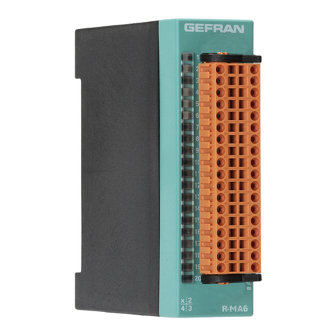
gefran
gefran R-MA6 Installation and operation manual
