Digimet 3000 User manual

DIGIMET ®3000
Vacuum and Pulsation Tester
Operator’s Manual – 4C
Digimet 3000 Version 4.0
L. J. Engineering, Inc.
Digimet 3000 Manual - 4C
January 2009
(Digimet 3000 Complete Pictured)

2
Dear Digimet User:
Thank you for your purchase of the Digimet
3000. It's a very good idea to read the
manual before operating any instrument,
such as your new DIGIMET 3000. Please
remember to read the manual thoroughly at
some point for a complete understanding of
the Digimet and its functions.
Thanks, again.
L. J. Engineering, Inc.

3
INTRODUCTION 6
PHYSICAL CHARACTERISTICS 6
Digimet 3000 Enclosure 6
Display 6
Keypad 6
Vacuum Input 6
Electronic Pulsator Input 7
RS-232 Serial Port (9-Pin) 7
Carrying Case 1 – Standard 7
Carrying Case 2 – Large Model 7
Fittings Supplied 8
SPECIFICATIONS 8
Power 8
Vacuum Input 8
Electronic Pulsation Input 9
Resolution and Accuracy 9
Calibration 9
FUNCTION 9
Auto Shutoff 10
Battery Low Indication 10
Reset 10
Data Display Hold 10
Store/Recall 11
Store 11
Store Graph 12
Recall 12
Print/Upload 13
Timer Stamp 15
Labeling 15
Table of Contents
Limping data 13
Figure A - Menu Navigation 14
Auto Zeroing 15
MENU & DISPLAY SYSTEM 16
Navigation 16
Display Standards 16
Battery Low Indication 16
Start-up Display 17
Function Menu 17
UTILITY MENU 17
Upload/Print all Data 18
Upload Graphic Data 18
Print Graph 20
Fluctuation Time Frame 20
Liner Collapse Point (LCP) 20
Display Units 20
Type of Pulsation Storage 20
Auto Shutoff 21
Clear Storage Memory 21
DISPLAYS 21
Vacuum Level Function Display 21
Pulsator Ratio Function Display 21
Milk/Rest Ratio Function Display 22
Pulsation-Electronic Function Display 22
Option Menu 23
Store/Recall Menus 23
Store Graph Menus 24
MEASUREMENT FUNCTIONS 24
Measurement Constants 24
Table of Contents (cont.)
Print Limping data 21
Available options – Figure B 22

4
Table of Contents (cont.)
Display Units 25
Type Pulsation 25
Auto Shutoff 25
Vacuum Level Function 25
Vacuum Fluctuation 26
Pulsator Ratio 26
Setting Pulsator Ratio Limits 26
B-Phase Fluctuation 27
Milk/Rest Ratio 28
Pulsation Electronic 29
CALIBRATION 29
Unit Initialization 29
Auto-Zero 29
HARDWARE SPECIFICATIONS 29
Microprocessor 29
Power Subsystem 29
Vacuum Sensing 30
Electronic Pulsation Input 30
DIGIMET PRINTER 30
Digimet Printer Settings 30
Digimet Printer Operations 30
SOFTWARE 31
Computer Requirements 31
DOS program Upload.exe 31
WINDOWS program DigiData.exe 31
Upload Item 32
Viewing Data 32
Notes 32
MENU: 32
Table of Contents (cont.)
File - New 32
File - Open 32
File - Save As 32
File - Set Printer Font 32
File - Print 33
File - Exit 33
Options - Label Data Set 33
Options - Set Com Port 33
Options - Type Pulsation 33
Options - Graphing 33
Options - Set Pulsator Limits 33
Options - View Pulsator Limits 33
View Grid or Standard 33
View Inches Hg or kPa 33
Graph Settings 34
Help 34
Upload item 34
Upload all 35
Upload Graph 35
Display Graph 36
Send to D. Printer (Not Used) 36
Rec. archive data (Not Used) 36
Graph data 36
Saving Files 36
When is Uploading complete? 37
Use of other programs 37
CABLES 37
PARTS LIST 37

5
Table of Contents (cont.)
MISCELLANEOUS 38
Tapping Holes 38
Comparing Electronic and Pneumatic
Pulsation
38
Cleaning 38
Use of Stainless Needle 39
Serial Number 39
Configurations 39
Packing List 39
Trademarks 40
Troubleshooting 40
Default Pulsator Ratio parameter Limits 40
ADDENDUM #1 40B
Viewing pulsator data 40B
Using kPa 40B
Pulsator limits not transferred 40B
Setting Pulsator Limits 40B
Testing data on CD 40B
Contents of CD 40B
Graphs & Printouts 41
Graphs - computer 47
Quick Reference Guide 48
Digimet Printer Instructions (Digimet Complete) 49
Limited Warranty 50
Contact Information 51

6
INTRODUCTION
The Digimet 3000 is a 5-key, hand-held,
battery operated, microprocessor-based
vacuum and pulsation multi-function
testing meter for measuring vacuum level
characteristics and pulsation attributes in a
milking system. The Digimet 3000’s stored
data can be either viewed on its LCD
screen, uploaded to a computer or printed
to the Digimet®Printer.
The Digimet 3000 stores and displays the
following types of information:
• Average Vacuum level
• Maximum Vacuum level until reset by
user
• Minimum Vacuum level until reset by
user
• Fluctuation level with user-set time
frames
• Pulsation ratio with A, B, C and D
phases in percentages and milliseconds
• Evaluation of the B phase - B Fluc
• Maximum and Minimum vacuum per
pulse
• Pulses per minute
• Pulsation Limits can be set for various
pulsation attributes.
• In the Pulsator Ratio Function when
limits are not met or exceeded the value
will blink.
• Unit calculates the Limping Ratio
• Milk/Rest ratio with user-selected Liner
Collapse Point
• Electrical pulsation with On versus Off
time, Maximum & Minimum voltage per
pulse, PPM
• Units measured may be Inches Hg
mercury or kilopascals (kPa)
• Data items can be labeled
• Up to five 10-second graphs can be
saved and later printed or downloaded.
Graphs can be printed to the Digimet
Printer or uploaded to a computer.
• Pulsator data can be stored as single or
dual pulsation.
• User set auto shut-off
PHYSICAL CHARACTERISTICS
Digimet 3000 Enclosure
The Digimet 3000 is enclosed in a durable
black ABS plastic case with dimensions of:
7.50” in length x 4.00” in width x 1.26” in
depth.
Display
The Digimet 3000 has a 16-character by 4-
row LCD dot-matrix display capable of
displaying the alphanumeric character set
plus additional characters (#, etc.). The
display supports the character attribute of
blinking. The front panel includes a
protective clear window to cover the
display.
Keypad
The Digimet 3000 has a front panel
consisting of a durable and washable
plastic face and integrated membrane key
switches, with access for all input
receptacles. The front panel incorporates
the following membrane keys:
The specific functions of these keys are
described in the section titled: MENU &
DISPLAY SYSTEM.
Vacuum Input
The Digimet 3000 has a 1/8” tube
receptacle located on the front panel for
attachment to an external vacuum source,
vacuum line, etc. The vacuum input will
not be damaged by the intrusion of
ON
OFF Menu Enter

7
moisture or liquids, but care should be
taken to prevent this from happening.
If, for example, milk were allowed to
enter the transducer and dry, the
performance of the transducer could be
affected. A filter is provided to keep liquids
from coming into contact with the
transducer. IMPORTANT: THE FILTER
MUST BE USED AT ALL TIMES.
If milk accidentally enters the transducer
area, the transducer should be rinsed with
water. Please refer to the section
Cleaning for further instructions. If milk is
allowed to dry inside the transducer, the
transducer will need to be replaced.
The Acrodisc filter will not allow milk to
pass through it. As long as milk is not
allowed to sit in the filter, milk will not
adhere to the filter membrane. Keeping the
filter clean will allow for repeated use.
Check the filter periodically to determine
whether it has become plugged or
restricted. To do this, check Digimet 3000
readings on one of the pulsation (vacuum)
Functions with and without the filter in
place. If similar readings are obtained then
the filter is not plugged.
The tube that comes out of the Digimet
3000 at the port labeled VACUUM is
connected to a quick-disconnect male
fitting (DM3-16-03). When the Digimet is
not in use, a white plug (DM3-16-06) plugs
the opening of the male fitting. When in
use, attach the Acrodisc filter (DM3-15) to
the male fitting and TIGHTEN. Attach to
the Acrodisc filter a 4’ length of 5/32”
plastic tubing which is used to connect the
Digimet 3000 to the vacuum system. Note:
the 5/32” tubing has a small tube clamp on
the end that connects to the Acrodisc. This
provides for a tighter fit to the smaller 1/8”
slip-fit end of the Acrodisc.
Three methods can be used to connect the
Electronic Pulsator Input
The DIGIMET 3000 has two banana jack
receptacles located on the front panel.
These jacks are located side-by-side with
a distance between them that
accommodates a standard 3/4" double
banana plug or single plugs as provided
with the unit. THE UNIT WILL FUNCTION
PROPERLY WITH EITHER POLARITY
OF INPUT.
RS-232 Serial Port (9-Pin)
This 9-pin serial connector is used to
connect the Digimet 3000 to either the
Digimet Printer or a computer. Cables are
provided. The serial port has a small
plastic dust cover for protection. This port
is labeled Serial.
Carrying Case – Standard
The DIGIMET 3000 padded canvas
carrying case is approximately 9" long x 5"
wide x 3 1/2" deep. Case includes a
compartment for the DIGIMET 3000 with
two inside straps to keep the unit in place,
and an additional compartment for storing
items such as vacuum tubing, banana
plugs, extra batteries, etc. A shoulder strap
is also provided.
Large Carrying Case
The Large Hard Carrying Case is
approximately 15-3/4” x 9-7/8” x 6-7/8”. It
is divided into compartments which
tubing to the vacuum system: 1) A needle
connector and stainless steel needle. Be
sure needle does not become plugged
during use. (See the section Use of
stainless needle.) 2. A “T” fitting is
supplied to accommodate plugging into
the short pulsation air tube without use of
a needle. 3) A 1/4” plastic pipe fitting with
a 5/32” nipple is also provided to tap into
plastic pipe systems, as well as a plastic
pipe plug to be used when the fitting is

8
accommodate the Digimet 3000, the
Digimet Printer, AC wall transformer (for
the printer) and accessories. A shoulder
strap is also provided.
Fittings Supplied with DIGIMET 3000
The Digimet can accommodate two types
of input: 1) vacuum; 2) electrical
pulsation. Fittings are supplied to facilitate
both forms of input.
Vacuum Port – The vacuum port is labeled
VACUUM and consists of a quick-
disconnect male luer fitting (DM3-16-03)
with a white plug (DM3-16-06) attached.
The white plug serves as prevention
against debris entering the vacuum port
when the unit is not in use. A quick
counter-clockwise turn will remove the
white plug from the male luer fitting.
During operation, the vacuum port with its
male luer fitting is attached to an Acrodisc
filter (DM3-15) which is connected to
approximately 4' of 5/32" tubing. A small
hose clamp is provided to secure the hose
to the Acrodisc filter, tightly. Note: the
Acrodisc filters should be used at all
times. To connect the free end of the
tubing to the vacuum system, the user has
several choices: 1) A needle connector
(DM3-Connector) is provided for use with
the stainless needle (DM3-17), which is
inserted into rubber components of the
milking system. (See section
Miscellaneous-Use of stainless needle.)
2) 5/32" nipples may be fitted into the
vacuum system for connecting the 5/32"
tubing. A sample of such a fitting is
provided with your Digimet 3000 (pipe
fitting DM3-PIPE and plug DM3-17-02).
The pipe fitting is a 5/32-27 NPT fitting.
See the section, Tapping holes, for
instructions on tapping holes for this fitting.
3) A pulsator tube adapter “T” fitting
(provided) can be used to check pulsation
line vacuum instead of using the stainless
needle. Connect opposing sides of the “T”
fitting to the short pulsation air tube at the
milk claw and the middle of the “T” to the
Digimet 3000 plastic tubing.
SPECIFICATIONS
This section defines the operating
conditions and performance specifications
which apply to the Digimet 3000.
Power
The Digimet 3000 operates on four AA
alkaline batteries. The Digimet 3000 will
operate for approximately 40 hours before
batteries need to be changed. When the
batteries are low, in the upper right-hand
corner, a “B” will blink, indicating low
battery level. The unit will still function but
the batteries should be replaced. If the
batteries are not supplying sufficient power
for the unit to function properly then the
screen will go blank and the unit will turn
itself off. The battery compartment is
located just behind the LCD display with
the opening on the back side of the unit.
Care should be taken to install batteries
in the proper direction. Data stored in
the Digimet is not affected by turning the
unit off. If the batteries are replaced,
however, they should be replaced within
an hour of removal or storage data will
be lost.
Vacuum Input
In this manual, VACUUM refers to a
differential pressure, with atmospheric
pressure as the reference. Zero vacuum
equates to a zero difference from
atmospheric pressure. Positively
increasing vacuum equates to a
decreasing of pressure relative to
atmospheric pressure (i.e. less than
atmospheric pressure).

9
The Digimet 3000 will accept a vacuum
input with the following characteristics:
Range — 0-18” Hg, equivalent to 0-60.9 kPa
Frequency — 30 -120 Pulses Per Minute,
equivalent to .5-2 Hz
Electronic Pulsation Input
The Digimet 3000 will accept an oscillating
electrical input from 0 volts to +/- 30 DC
volts. Over-voltage protection is provided
for inputs up to 50 DC volts so that the unit
will not be damaged. The electrical input
accommodates up to 40 amps. The
polarity of the input signal is rectified to
guarantee that all voltages are positive. An
internal filter is incorporated to eliminate
sharp voltage spikes that occur during
solenoid switching. DO NOT TOUCH
CONNECTORS TO 110-VOLTS OR 220-
VOLT AC INPUTS.
Resolution and Accuracy
Vacuum Display and Unit Relationships
All vacuum (pressure) measurements will
be displayed according to the selected
Vacuum Display Unit. The available units
are Inches of Mercury (“Hg) and
kilopascals (kPa).
The following provides an orientation to
the equivalency of various pressure units:
1 atm ≈30.0” Hg ≈14.7 psi ≈ 101 kPa
The actual conversion factor used is:
1” Hg = 3.3864 kPa
The following resolutions are used:
Units Precision Display Range Example
“Hg 100ths 18.00 12.05
kPa 10ths 60.9 45.5
The performance specifications for the
various measurement types are defined in
the table below. Specifications are for the
entire operating range of the Digimet
3000, and for a temperature range of 32-
150 degrees Fahrenheit.
Calibration
The Digimet 3000 is factory calibrated. Its
components are designed so that losing
calibration is unlikely, but if the unit is
subjected to harsh environments or
treated roughly, it may need factory
recalibration at some future time. But, as
any electronic instrument, yearly
recalibration is recommended.
FUNCTION
This section describes the operation and
features of the Digimet 3000.
The functions of the Digimet 3000 are
divided into the following areas:
System Functions
Auto Shutoff
Battery Low Indication
Reset
Data Display Hold
Store/Recall
Store Graph
Print/Upload
Limping data
Timer Stamp
Labeling
Auto Zeroing
Measurement Units Resolution Accuracy
Vacuum “Hg 0.01 +/-.06
Vacuum kPa 0.1 +-.2
Time msec 1+-1
PPM ppm 0.1 +-.1
Ratio %0.1 +-.1
Voltage DC Volts .1 +-.3

10
Menu & Display System
Measurement Functions
Vacuum Level
Pulsator Ratio
M/R Ratio
Pulsation Electronic
Utilities
Upload/Print all data
Upload Graph
Print Graph
Fluctuation Time Frame
Liner Collapse Point
Type of Pulsation Storage
Display Units - “ Hg or kPa
Type Pulsation - Dual/Single
Auto Shutoff
Clear Storage Memory
Print Limping Data
Set Pulsator Limits
The measurement Functions are fully
independent from one another. Information
(unless it is “stored”) is not retained when
switching from one Function mode to
another.
Auto Shutoff
The Digimet 3000 provides for automatic
shutoff of the unit after a user selectable
period of time from 0 to 30 minutes of non-
use. This is set in the Utility Menu, item
number eight. See section on Utility
Menu. This feature is designed to
maximize battery life. “Use” of the unit is
defined as presses on the front panel
keys. Each depression of a key will cause
an internal timer to reset to zero. This
timer is continually counting, and when it
reaches the specified time, the Digimet
3000 will shut off. When the Digimet 3000
is auto-shutoff, all currently displayed
information will be lost, the same as if a
user had switched the unit off. (Stored
data is not lost.) When the unit is auto-
shutoff and subsequently turned back on,
it will perform the normal start-up
sequence defined in the section entitled
Start-up Display.
Battery Low Indication
The Digimet 3000 detects when the
battery power is low and displays a
message. The Low Battery indicator is a
blinking “B” in upper right corner of the
screen. See more about the Battery Low
Indication under heading MENU &
DISPLAY SYSTEM.
Reset
The Vacuum Level Measurement function
has the ability to “reset” the Max. and Min.
Vacuum readings. Vacuum Level Min/Max
Reset is further discussed in the section
entitled Vacuum Level Function.
Data Display Hold
The Digimet 3000 has the capability to
“freeze” the data currently displayed, with
the use of the Hold mode. The entire set of
measurements for a Function that is held
will be frozen, including items not visible
within the display window. This allows the
user to scroll through all measurements.
When placed in Hold mode, the Digimet
3000 will continue to sample input and
calculate the measurements for the current
function; however, the display will not be
updated with the current information, but
will display the measurements at the time
the unit was placed in Hold mode. When
accessing the Option Menu to utilize Hold,
within a particular Function, the MENU key
must be pressed. The data that is on the
screen the instant the Menu key is pressed
will be the data held.
When the Digimet 3000 is then placed in
the Continue mode, the display will be
updated with current measurements. This
operation is analogous to a split-time
feature of a stopwatch. The Hold mode is
automatically released when the
measurement Function is exited. For
example, if the unit is in Hold mode within

11
the Vacuum Level measurement Function
and then the Pulsator Ratio Function is
selected, the Pulsator Ratio function will
begin in the Continue mode.
All measurement Functions have the Hold
mode capability.
Store/Recall
The Store/Recall function allows for the
storage of screen data within the Digimet
3000’s memory, and for the recall to the
Digimet display, printing to the Digimet
Printer or uploading to a computer.
Store
The Store function of the Digimet 3000
allows a measurement set to be stored for
later viewing (recall) or uploading (to a
computer) or printing (to the Digimet
Printer). A measurement set contains all
measurement parameters of the Function
being stored plus a label of up to 16
characters or if no label is inputted a timer-
stamp will be associated with the data.
This data is stored into dedicated storage
slots (selected by the user) and remains in
storage even if the unit is turned off and
back on.
Each measurement Function contains a
maximum number of measurement sets
that can be stored, and each slot is
numbered. This means that storage space
reserved for a particular Function cannot
be used by any other Function.
The following storage is provided:
Measurement # Storage Slots
Vacuum Level 10
Pulsator Ratio 60
M/R Ratio 30
Pulsation Electronic 5
Graph Storage 5
Some measurements require a minimum
start-up time before data is displayed (see
section titled MEASUREMENT
FUNCTIONS). This is generally
approximately two or three seconds,
depending on the measurement. If the
required start-up time has not elapsed, the
Store option will not be available, it is
surrounded by < > on the display screen.
If the unit is in the Hold mode the held data
will be stored. Otherwise, the data that is
current at the time Store is selected will be
stored.
When the Store screen appears, choose the
storage slot number where the data is to be
stored. An empty slot has neither a timer-
stamp or a label next to it. The next screen
will allow a label to be attached to the item
being stored. The top of the screen will
indicate “Label Slot 01”. The 01 would
change depending on the number of the slot.
Below this, there will be 16 hyphens
indicating 16 available characters for the
label. The cursor will be all the way to the left
under the first character. Choose characters
for the label by using the up and down arrow
key on the keypad. The up arrow key will
start with A,B,C,D and so on through some
symbols and numbers. The down arrow key
starts with the (space),#,0,1,2 and so on.
Once the character is chosen, press the
Enter key to advance to the next character.
When done with the label press the Menu
key to Save. If the Menu key is pressed
without selecting any characters for a label, a
timer stamp will be associated with the data
stored. This timer-stamp is described in the
section Timer-Stamp. Once the item is
saved, the Option Menu will re-appear.
Store Graph
This option appears in all three of the
pneumatic functions in the Function Option
Menus. The time period for graph length is

12
set at this time from 2 seconds to 10
seconds. Up to five separate graphs from
2 seconds to 10 seconds each, can be
stored. On subsequent store graphs the
unit will remember storage time and will
not need to be changed unless you desire
a different time period. Please note: It is a
good practice to match the fluctuation time
frame - a variable in the Vacuum Level
Function (set in the Utility Menu), with the
store graph time period so the numeric
data printed out on the graphs, matches
the activity of the graph. For example, you
would want to set the Fluctuation Time
Frame to 3 seconds (Utility Menu item #4)
if you wanted a graph period of 3 seconds.
This practice is only applicable for the
Vacuum Level Function. The Fluctuation
Time Frame is not a variable in the other
pulsation functions. Another note
regarding Fluctuation Time Frame and
Graphing time: If the Fluctuation Time
Frame is less than the Graph time, then
the Fluctuation figure, which will print-out
on the graph, will cover the last portion of
the graph which includes the period of the
Fluctuation Time Frame. For example, if
the Fluctuation Time Frame is 2 seconds
and the Graph time is 3 seconds then the
Fluctuation figure will be for the last 2
seconds of the 3 second graph. If the
Fluctuation Time Frame is greater than
the Graph time, then the Fluctuation figure
will be for the time period of the graph. For
example, if the Fluctuation Time Frame is
set for 5 seconds and the Graph time is for
3 seconds, the Fluctuation figure will be for
3 seconds.
When you first enter Store Graph, a
screen will appear with 5 storage slots.
After choosing the slot the next screen will
allow a label. It is not necessary to choose
a label. In the case where no label is
chosen the graph will have a timer stamp
associated with it. When the label screen
is exited, the screen will indicate, Enter for
3 sec. of graph. Up/Down changes.
Menu to exit. (This assumes that 3
seconds is the chosen graph period). Time
can be set from 2 seconds to 10 seconds.
Pressing the appropriate key will either exit
without saving or you will enter the
function in the Recording Mode. In this
mode an Rwill appear in the upper right
corner of the Digimet screen. There is a
short delay before the unit begins Storing
the graph. When the Rbegins to blink,
storing data has begun. The initial delay
allows the readings to stabilize. Note: If
you want to capture a particular
activity, start the activity the moment
the “R” starts to blink.
After the Rstops blinking, storage is
complete. You can now use Print Graph
to graph to the Digimet Printer or use
Upload Graphic Data to upload graph
data to the computer for viewing on the
Computer Screen. Upload Graphic Data
and Print Graph are both options that
appear in the Utility Menu, item 2 and 3.
The reason for these different options is
because the Digimet formats the data
differently depending on the ultimate way
that the data will be viewed.
Recall
Data that has been previously stored may
be recalled for display by the Digimet
3000. The particular measurement set that
will be recalled depends on the current

13
measurement Function. That is, the
Digimet must be in a measurement
Function for this option to be available. If a
slot does not contain any stored data, the
Digimet will not allow selection of that slot
for recall.
When the RECALL screen appears, if
there is stored data in a particular slot,
there will be either a label or a timer-stamp
next to the numbered slot. Only twelve
characters of the label will appear in the
Store screen.
When data is recalled, it is displayed on
the Digimet 3000 display in the same
format as during normal sampling
operation, except that the recall slot
number appears (blinking) at the upper
right corner of the display screen. Both
recalled data and held data can be stored
in multiple slots, allowing the user to “make
a copy”.
Print/Upload
The Print/Upload function allows the user
to Print an individual item to the Digimet
Printer or Upload an individual item to a
computer via a serial port. In order to print,
the Digimet Printer must be connected to
the Digimet 3000 (See section on the
Digimet Printer). The printer cable
supplied with the Digimet Printer has a 25-
pin male serial connector at one end and a
9-pin male serial connector at the other.
The 9-pin end connects to the Digimet
3000 and the 25-pin end connects to the
Digimet Printer. The next step is to supply
the Digimet Printer with power using the
supplied AC wall transformer. Turn the
Digimet Printer “ON”. Press the Enter key
to select Print/Upload. A screen will appear
with storage slots identified along with
either labels or timer-stamps (same as in
Recall). Choose the item to Print/Upload
by selecting the item with the up and down
arrow keys. Select the item by pressing
the Enter key. The next screen will indicate
that the numbered slot with the attached
label will be sent. Press Enter to send,
Menu key to exit without printing or
uploading the item. If there is a loose cable
connection or the Digimet Printer is not
“ON” then an error message “No Clear to
Send” will appear and remain on the
screen. If the “No Clear to Send” remains
on the screen, then press the Menu key to
exit and the connection problem must be
corrected. If all is OK then the item data
will be sent to the Digimet Printer.
The above procedure would be identical
for Uploading an item to the computer
accept for a few differences. To upload,
the supplied 6’ computer cable (supplied
with the Basic Digimet 3000) which has 9-
pin connectors at each end, one is a
female and one is a male connector, must
be used. The male end attaches to the
Digimet 3000 and the other to the
computer. The second difference would be
that the software to upload data from the
Digimet 3000 must be loaded and running
on a computer to complete the upload
procedure. Other than these two
differences the steps for Uploading would
be the same as for Printing. For
information on the software requirements
for uploading data from the Digimet to a
computer, see the section on
SOFTWARE.
Limping data
In versions greater than 3.2, a feature was
added to the Pulsator Ratio Function
called the Limping data.
The difference in the milking ratio of the
right and left sides of the pulsator is
referred to as “limping ratio”. Limping may
be caused by plugged or worn small air
tubes, plugged or leaking pulsator tubing,
14
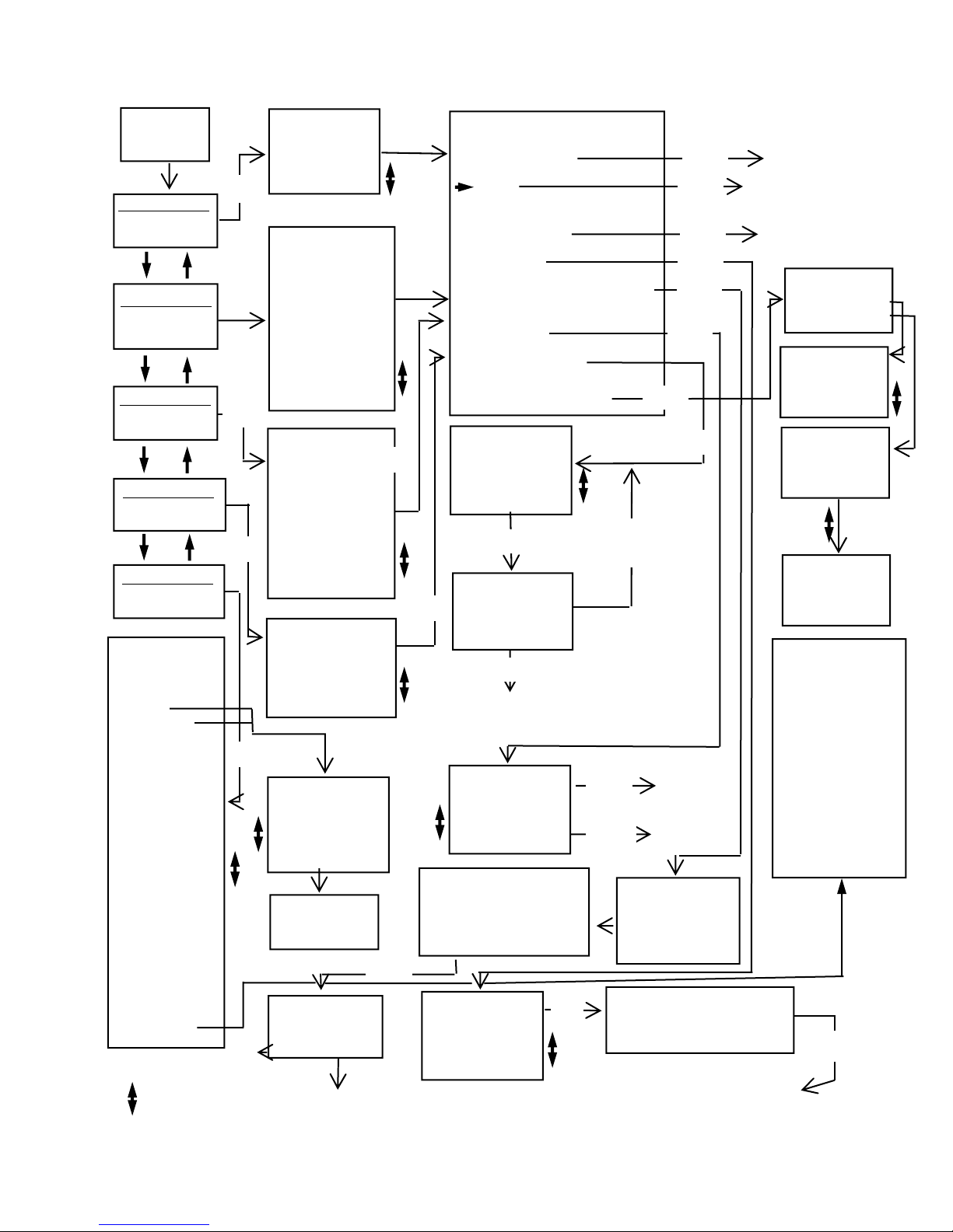
Figure A - Menu Navigation
Start-up
Screen
FUNCTION MENU
Vacuum Level
FUNCTION MENU
Pulsator Ratio
FUNCTION MENU
M/R Ratio
FUNCTION MENU
Utility Menu
FUNCTION MENU
Pulsation Electronic
VACUUM LEVEL
Ave 0.00 “Hg
Max 0.00 “Hg
Min 0.00 “Hg
Fluc 0.00 / 1s
Enter*
PULSATOR RATIO
A+B 60.2% 699ms
C+D 39.8% 463ms
B Fluc 0.43”Hg
Max/P 10.63”Hg
Min/P 0.00”Hg
A 5.3% 61 ms
B 54.9% 638 ms
C 5.7% 66 ms
D 34.1% 397
ms
Total 1162
-OPTION MENU
Function Menu
Hold
Reset (Only for Vacuum Level
Function)
Store
Store Graph (not for Pulsation
Electronic)
Recall
Print/Upload
Limping data (Only for
Pulsator Ratio Function)
Enter
Back to
Function
Menu
Enter Back to
Function in Hold
Enter Back to
Function
Enter
Menu
*
M/R RATIO
Ratio 63:37
PPM 54.2
Max/P 13.59 “Hg
Min/P 0.02 “Hg
Milk 63.3 %
Milk 701 ms
Rest 36.7 %
Rest 405 ms
LCP 6.50 “Hg
TTime 1106
PULSATION ELEC 01
On 60.4%
Off 39.6%
Max/P 10.2 Volts
Min/P 0.0 Volts
PPM 60.4
* Use Up & Down
Arrow Keys
-UTILITY MENU
1Upload-Print all
Data
2 Upload Graphic
Data
3 Print Graph
4 Fluc. Time
Frame >1 2 3 4
5 10 sec
5 Liner Collapse
Point Equals
LCP= 6.5 “Hg
6 Type Pulsation
>Dual
Single
7 Units
>Inches Hg
kPa
8 Auto Shutoff
30 minutes
9 Clear
Storage
Memory
10 Print limping
data
11 Set Pulsator
Limits
Press Enter to
start graphing
Menu to exit.
RECALL 09:06:14
> 01 BARN #1
02 MILK TRAP
03 08:12:00
Send Slot 01
BARN #1
Enter to send
Menu to exit.
Back to
Function
Menu - back to
Option Menu
To Printer or
Computer then back
to Option Menu
Enter
Enter
Enter
Enter for 3
sec. of graph
Up/Down changes.
Menu to exit.
STORE 09:06:14
01 BARN #1
02 MILK TRAP
03 08:12:00
> 04
Label Slot 09
_ _ _ _ _ _ _ _ _ _ _ _ _ _ _ _
Menu to Save.
Enter
Save then To
Option Menu
Menu
PRINT 09:06:14
> 01 BARN #1
02 MILK TRAP
03 08:12:00
Enter
Menu
Back to
Option
Menu
Enter
(Enter to move cursor)
Enter
Enter
Menu
Enter
Enter
Enter
Enter
GRAPH
09:06:14
> M01 BARN #2
V02 MILK TR
P03 08:12:15
GRAPH 01:16:58
> 01 BARN
02 MILK
03
Label Graph 01
_ _ _ _ _ _ _ _ _ _ _ _ _ _ _
Menu to Save.
Back to function in record mode
Menu to
Exit
Menu
Menu
Menu
Enter
LIMPING
> View one
item
LIMPING
> 01AB Available
02AB Not Avail.
03AB Not Avail.
LIMPING
01AB Limping
0.2 %
1 msec
LIMPING
02AB Not Avail.
(press the down arrow
key for more items)
Set Limits:
Bfluct Max 0-3.00
MaxHiV/Pls 5.5-
16.00
MinHiV/Pls 5.0-15.50
MinVac/Pls 0-4.00
MaxAPhase 20-300
MinAPhase 20-300
MaxBPhase 100-750
MinBPhase 100-750
MaxCPhase 20-500
MinCPhase 20-500
MaxDPhase 100-500
MinDPhase 100-500
Max PPM 20-198

15
as well as the pulsator itself.
When using the Digimet 3000 in the Dual
Storage Mode, pulsator data is stored in
slots labeled 01A, 01B, 02A, 02B ... 30A,
30B. When both the A and B slots are
filled with pulsator data, the Digimet will
calculate the Limping data. The Limping
data is an item which appears in the
Option Menu of the Pulsator Ratio
Function. The Limping data will appear as
a percentage and in milliseconds.
The Digimet 3000 evaluates the A + B
phase of each side of the pulsator and
indicates the difference as a percentage
and in milliseconds. For example, Limping
data would appear as follows:
07AB Limping
0.1 %
2 msec.
The Limping data can be viewed on the
Digimet’s display, printed to the Digimet
Printer or uploaded to a computer for
viewing and/or printing. The printing of
Limping data from the computer is
available on the DigiData program version
3.4 and greater.
Timer Stamp
In conjunction with the Store/Recall
function, a clocking mechanism is built in.
The purpose of this clocking mechanism is
to provide an internal real-time counter
that is used to timer-stamp the stored
measurement data. Unless a label is
chosen the timer-stamp will appear in the
Store, Store Graph, Recall, Print/Upload,
Upload Graph and Print Graph screens.
When an item is printed or uploaded the
timer-stamp in addition to the label, if
chosen, will appear. The clock will
increment every second with a range of
12:00 hours. Thus when the clock reaches
11:59, the next increment will roll the clock
over to 00:00.
Labeling
When storing data or graphs, prior to
storage but after choosing the storage slot,
a screen will appear giving you the
opportunity to label your stored item. You
can use up to 16 characters. Use the up
and down arrows to choose the character/
number/symbol. Press the Enter key to
advance to the next character. Holding the
arrow keys down for more than two
seconds will advance the characters
automatically. When done with your label
pressing the Menu key will exit and save
your data or graph. Exiting, with the Menu
key, without entering labeling will attach a
timer stamp to your data. So, it is not
mandatory to choose a label.
Auto Zeroing
The Digimet 3000 has an auto-zero
capability. Due to temperature variations
which can affect certain components, the
Digimet 3000 is designed to auto zero.
This takes place any time the Digimet is in
the Vacuum Level Function or one of the
pulsation (vacuum) Functions with NO
VACUUM INPUT applied. At this time, the
Digimet displays all zeros for Avg Vac,
Max Vac, Min Vac, and Fluctuation. (Note:
If the unit has just displayed vacuum
readings, it may be necessary to reset
Max Vac before a zero reading is
obtained.) The Pulsation (vacuum)
Functions will appear blank when auto-
zeroed.
Therefore, the following procedure is
recommended: When taking Vacuum
Level of pulsation (vacuum) Function
measurements, periodically take a
reading with no vacuum input to allow
the Digimet 3000 to auto-zero.

16
The Menu key is used to access menus.
The Digimet utilizes "pop-up" menus which
are easily accessed with the Menu key.
Navigation
Navigation through the Digimet menus and
functions is illustrated in Figure A page 14.
Display Standards
The design of the display system follows
some basic standards in order to provide a
consistent user interface.
The top line will always display a title in
capital letters, indicating the purpose of the
current screen. This will either be the name
of a menu or the name of a measurement
Function. This title line does not scroll.
Hold Indicator: For all measurement
Function displays, the top right two character
spaces are designated for indicating that the
unit is in Hold mode. Hold mode is signified
by the presence of a single, blinking
character "H". Sampling or real-time mode
is indicated by the absence of the character
"H".
Recall Indicator: The same two character
spaces (top right) are reserved to indicate
the number of a recalled set of
measurements. The recall function is
described in section titled Store/Recall.
Battery Low Indication
A low battery, as detected by system
circuitry, will be indicated on the display by a
blinking "B" in the display status area (upper
right corner).
The battery low indication (blinking "B") on
the display means the batteries will soon
MENU & DISPLAY SYSTEM
The menu system is navigated via the
front panel keys. The basic menu/function
structure is depicted in Figure A on Page
14. The structure and operation of the
menu/display are designed to provide
easy access to all of the Digimet 3000
features.
The use of the keys is as follows:
These keys are used to scroll the screen.
For menus, these keys are also used to
change the current selection. Once the
bottom of a screen has been reached (or
the last item selected), subsequent
pressing of the down arrow will have no
effect, that is, the screen will not loop back
to the top. Similarly, pressing the up arrow
will have no effect after the top of the
screen is reached. The arrow keys are
also used to change data in the Utility
Menu and to choose letters or characters
for labels. Both to be described in a later
section.
The Enter key is used to make a selection
or a change of some kind. This could be
changing to a new Function, changing a
system parameter, etc. But this key is
always associated with some effect on the
Digimet system.
Enter
Menu

17
expire, causing the unit to cease
functioning. The unit will operate properly
for several hours after the low battery
indicator appears on the screen.
IMPORTANT: STORED DATA IS NOT
LOST WHEN THE BATTERIES EXPIRE
OR ARE REMOVED FOR
REPLACEMENT, ASSUMING THAT
FRESH BATTERIES ARE REINSTALLED
WITHIN AN HOUR.
Start-up Display
Each time the Digimet 3000 is turned on,
the following initial screen will be
displayed:
This start-up screen will be displayed for 5
seconds.
The following screen layout diagrams
(shown on the next couple of pages)
illustrate two ways in which a screen is
scrolled. The first is as a "page." A
screen with a page scroll displays lines in
sets of three (excluding the top line which
does not move). These three-line page
groupings are identified by shading. The
second method of scrolling is a single-line
scroll, in which individual lines are scrolled
continuously (rather than in groups as with
the page scroll).
Function Menu
The Function Menu is the system's main
menu. It allows the selection of a
particular measurement Function or of the
Utility Menu.
After the initial Start-up Display, the
selection on the Function Menu will default
to the first option. Upon selection of an
option from the Function Menu, and
subsequent return to the Function Menu,
the last-selected item will be the default
selecti
Action of Keys
Menu None
Enter Go to selected measurement
Function or Utility Menu
Up arrow Previous item on Function
Down arrow Next item on Function Menu
UTILITY MENU
The Utility Menu allows the user to change
several Digimet settings which include:
•Upload/Print all data
•Upload Graph
•Print Graph
•Fluctuation Time Frame
•Liner Collapse Point
•Type of Pulsation storage
•Display Units
•Auto Shutoff
•Clear Storage Memory
-FUNCTION MENU
1 Vacuum Level
Avg Vac,Min&Max
Fluctuation
2 Pulsator Ratio
ABCD% &ms,Min/P
Max/P PPM
3 M/R Ratio
LCP= 6.50
Max/P Min/P PPM
4 Pulsation-Elec
On/Off PPM
Max Volts DC
5 Utility Menu
Settings for
Functions
LJE,Inc.
Digimet 3000
Ver 4.0 SN:00001
Copyright 2004

18
-UTILITY MENU
1 Upload-Print all
Data.
2 Upload Graphic
Data.
3 Print Graph
4 Fluc. Time
Frame 1 >2 3 4
5 10 sec
5 Liner Collapse
Point Equals
LCP= 6.5 “Hg
6 Type Pulsation
Dual
>Single
7 Units
>Inches Hg
kPa
8 Auto Shutoff
10 minutes
9 Clear
Storage
Memory
10 Print
Limping data
11 Set Pulsator
•Print Limping data
•Set Pulsator Limits
The Utility menu is depicted above:
Action of Keys
Menu Return to Function Menu
Up arrow Previous screen/selection
Down arrow Next screen/selection
Enter Edit the value on the displayed
screen
The > symbol points to the current setting.
The enter key is used to access the
Editing mode, which is indicated by a
blinking "E" in the upper right of the
display. While in Editing mode, the (up
arrow) and (down arrow) keys function to
change the current value. Edit mode may
be exited by either pressing the Enter key
to save any changes, or pressing Menu to
abandon any changes that have been
made in the current setting. The editing of
the various settings is described in the
following paragraphs:
Upload-Print all Data
Pressing the Enter key will initiate
transmission of data to either the Digimet
Printer or a waiting computer. The Digimet
Printer must be on if printing is to take
place otherwise an error “No Clear to Send”
will appear at the bottom of the screen. If
transmission is to a computer then the
receiving program must be up and running.
If not or there is a poor cable connection
between the Digimet and the computer the
same error will appear, “No Clear to Send”.
To exit without sending data to the printer
or computer press the Menu key. Note: If
you get no response from the printer after
attempting to print or data that was sent
appears garbled, turn the Digimet OFF then
ON. If you are using the Digimet Printer,
unplug it. Sometimes resetting either
device by turning OFF then ON or
unplugging, will solve the problem. Data
once stored in the Digimet is not lost even if
an upload fails. The data is securely stored
in the Digimet Memory. To erase stored
memory you would have to Clear Storage
Memory (ninth item in the Utility Menu) or
leave the unit without batteries for more
than an hour. This command will upload or
print to the Digimet Printer all numeric data.
Graphs must be printed or uploaded
separately. See Upload Graphic Data (Item
2 in the Utility Menu) and Print Graph (Item
3 in the Utility Menu).
Upload Graphic Data
This Utility Menu item is used to upload
graphs from the Digimet to a computer.
These graphs are formatted to be viewed
on the computer screen and, ultimately,
they can be printed to the computer’s
printer. They are not intended to be sent
to the Digimet Printer. However, if the
raw data is desired, as shown below,

19
• Press the “Press Digi then Here”
button. Button changes to
“******Uploading.” As uploading is
taking place this button will change to
“*****Still Uploading”. When uploading
is completed the button will say “*Done
Uploading”. The Save Graphic file
window will then appear. Choose a
name for your graph file and be sure it
ends with .dgr.
• Press the OK button in the Save
Graphic files window.
• Your graphic file has been uploaded
from the Digimet and saved as a
computer file.
If, however, the message, “No Clear to
Send” appears and remains, then the
Digimet does not have a good connection
or something is wrong with the hookup. If
this happens, pressing the Menu key will
exit the screen and the connection
problem will have to be solved.
The steps are listed here again for
Uploading graphic data from the Digimet to
the Computer.
1. Connect the 6 foot serial cable to the
Digimet and the computers serial port.
2. Open the Digidata program.
3. Go to the UTILITY MENU item 2
Upload Graphic Data on the Digimet.
4. Press Enter on the Digimet.
5. Choose your Graph to upload on the
Digimet.
6. Press Enter on the Digimet, one time.
7. Press the Upload Graph button on the
Digidata computer screen, the button
will change to “Press Digi then Here”.
8. Press Enter on the Digimet one more
time.
time “Hg
.000 12.00
.008 12.01
.016 12.02
(etc.)
you can Upload Graph Data to the Digimet
Printer. The print-out will include all the
time and vacuum data in numeric form, not
a graph. There are 125 readings made
each second. So, for a two second graph,
the raw data will consist of 250 readings.
After pressing the Enter key, the Graph
storage menu will appear. There are 5
storage slots for graphs. If there are stored
items, the slots will either have a timer
stamp next to the slot number or there will
be a label which would have been put in at
the graphing time. Also, the slot number,
01, 02, 03, 04, or 05 will have either a V for
Vacuum Level, P for Pulsator Ratio or a M
for Milk/Rest Ratio in front of it, to
designate which function the graph
originated from. Once you choose the slot
pressing the Enter key, the next screen will
be “Press Enter to start graphing. Menu
to exit.” At this point, before pressing the
Enter key again, the Digimet 3000 should
be connected to a serial port of a computer
with the 6 foot serial cable provided. The
DOS program or Windows program
provided should be up and running on the
computer in order to accept the uploaded
graph. The following will be the steps to
take utilizing the Windows Program
provided – Digidata. Explanation of
uploading using the DOS program can be
found in the SOFTWARE section.
• Press the Upload Graph button on the
Digidata computer screen, the button
will change to “Press Digi then Here”.
• Press Enter on the Digimet one more
time.

20
9. Press the “Press Digi then Here”
button. Button changes to
“******Uploading.” As uploading is
taking place this button will change to
“*****Still Uploading”. When uploading
is completed the button will say “*Done
Uploading”. The Save Graphic file
window will then appear. Choose a
name for your graph file and be sure it
ends with .dgr.
10. Press the OK button in the Save
Graphic files window.
11.Your graphic file has been uploaded
from the Digimet and saved as a
computer file.
Print Graph
This Utility Menu item is used for printing
graphs to the Digimet Printer. These
graphs are only formatted for the Digimet
printer.
Pressing the Enter key will bring up the
Graph storage menu (same menu as in
Upload Graphic Data). Choose the slot to
print.There are 5 storage slots for graphs.
If there are stored items, the slots will
either have a timer stamp next to the slot
number or there will be a label which would
have been put in at the graphing time.
Also, the slot number, 01, 02, 03, 04, or 05
will have either a V for Vacuum Level, P for
Pulsator Ratio or a M for Milk/Rest Ratio in
front of it, to designate which function the
graph originated from. Once you choose
the slot pressing the Enter key, the next
screen will be “Press Enter to start
graphing. Menu to exit.” At this point,
before pressing the Enter key again, the
Digimet 3000 should be connected to the
Digimet Printer and the Digimet Printer
should be on. Pressing Enter again will
initiate the printing of the graph on the
Digimet Printer.
Fluctuation Time Frame
While in Time Frame Edit mode, the up
arrow key will move the marker to the left
and the down arrow key will move the
marker to the right, indicating the selected
setting. Fluctuation time frame can be set
to 1, 2, 3, 4, 5 or 10 seconds. The
Fluctuation time frame establishes the time
frame for the variable - Fluctuation in the
Vacuum Level Function. The Digimet is
looking for the Max and Min value over the
period set here and outputs that difference
to the display and calls it Fluctuation.
Liner Collapse Point (LCP)
While in the LCP Edit mode, the up arrow
and down arrow keys are used to increase
or decrease the liner collapse point.
Prolonged pressing down of the key will
cause rapid advance of the value. LCP
can be set from 0.0 inches Hg/0.0 kPa to
18.0 inches of Hg/60.9 kPa.
Display Units
While in the Display Units Edit mode, the
up arrow and down arrow keys are used to
position the marker next to the desired
setting. Choices for display units are
Inches Hg and kPa.
Type of Pulsation Storage
Storage slots for the pneumatic functions
of Pulsator Ratio and Milk/Rest Ratio can
be either numbered 1,2,3,4, etc. (Single
pulsation) or 1A, 1B, 2B, 2C, etc. (Dual
pulsation). Use the up and down arrow
Table of contents
Popular Test Equipment manuals by other brands

SEAWARD Electronic
SEAWARD Electronic PAC3760 plus II operating instructions

WT
WT PH 2066UK Installation operation & maintenance

Silverline
Silverline 196602 quick guide

Ocean Optics
Ocean Optics XE-1 Xenon Installation and operation instructions

Precision Rated Optics
Precision Rated Optics TP-P6 manual

Agilent Technologies
Agilent Technologies InfiniiVision MSO6104A Service note


