MITECH MH660 User manual

1
mvip@mitech-ndt.com
CONTENTS
1 Introduction............................................................................................................................................................ 2
1.1 Features of the instrument......................................................................................................................... 2
1.2 Technical specifications..............................................................................................................................3
1.3 Standards and regulations applied...........................................................................................................3
1.4 Operating conditions...................................................................................................................................3
1.5 Application examples.................................................................................................................................. 3
1.6 Scope of delivery.........................................................................................................................................4
2 Product Feature.................................................................................................................................................... 4
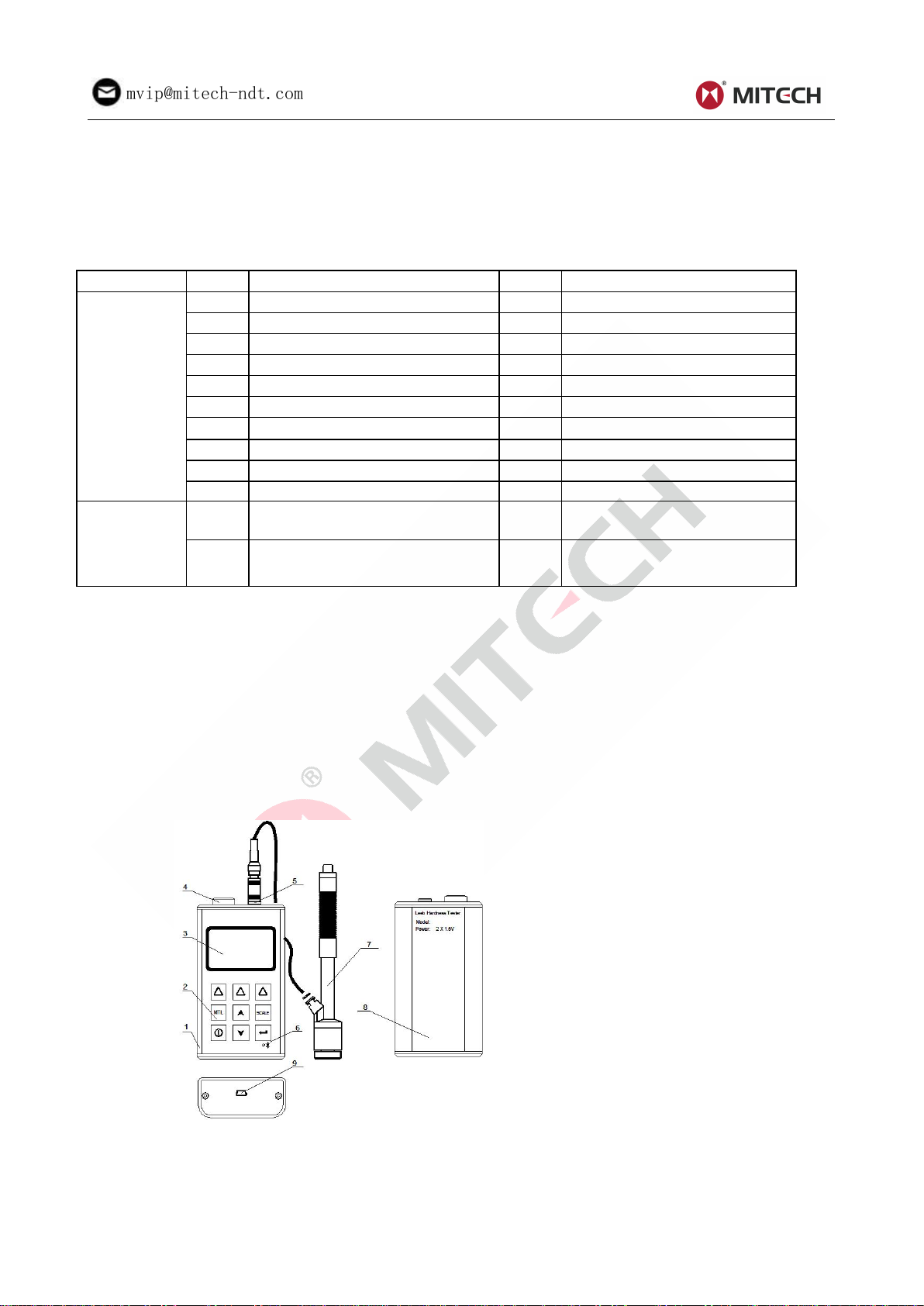
2.1 Structure feature..........................................................................................................................................4
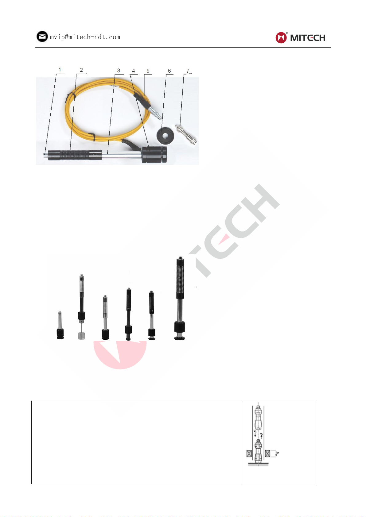
2.2 Impact device D........................................................................................................................................... 5
2.3 Other impact devices.................................................................................................................................. 5
2.4 Leeb rebound principle for hardness testing.......................................................................................... 5
2.5 Screen display............................................................................................................................................. 6
2.6 Keypad.......................................................................................................................................................... 6
2.7 Measuring conditions..................................................................................................................................7
3 Startup..................................................................................................................................................................... 7
3.1 Power supply................................................................................................................................................7
3.2 Connecting the instruments.......................................................................................................................7
3.3 Starting the instrument............................................................................................................................... 7
3.4 Configuration of the standby settings...................................................................................................... 8
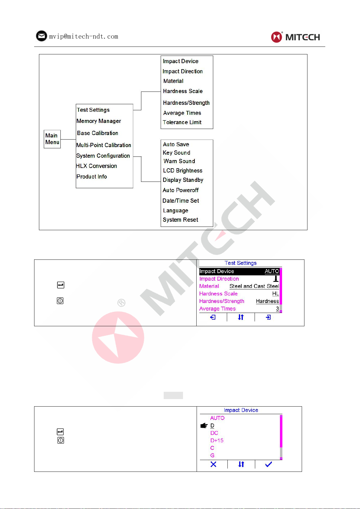
4 Settings................................................................................................................................................................... 8
4.1 Test settings................................................................................................................................................. 9
4.2 Memory manager...................................................................................................................................... 12
4.3 Base calibration (Impact device calibration).........................................................................................12
4.4 Multi-point calibration............................................................................................................................... 13
4.5 System configuration................................................................................................................................ 14
4.6 HLX conversion function..........................................................................................................................16
4.7 Product information...................................................................................................................................17
4.8 Replace the batteries............................................................................................................................... 17
4.9 Communication..........................................................................................................................................17
4.10 Print via Bluetooth...................................................................................................................................17
5 Operation.............................................................................................................................................................. 18
5.1 Preparation of the sample....................................................................................................................... 18
5.2 Triggering the impact................................................................................................................................ 20
5.3 Conversion Deviations............................................................................................................................. 20
Number of impacts per measuring area...................................................................................................... 21
6 Fault and Troubleshooting.............................................................................................................................. 22
7 Maintenance, storage and care...................................................................................................................... 22
7.1 Performance check (before each use).................................................................................................. 22
7.2 Maintenance.............................................................................................................................................. 23
7.3 Transport and storage conditions...........................................................................................................23
7.4 Cleaning (after each use)........................................................................................................................ 24
7.5 Warranty..................................................................................................................................................... 24
7.6 Tips on safety.............................................................................................................................................24
Appendix.................................................................................................................................................................. 25
Table 1...................................................................................................................................... 25
Table 2...................................................................................................................................... 26
Table 3...................................................................................................................................... 27
Table 4...................................................................................................................................... 28
User Notes................................................................................................................................................................29

2
mvip@mitech-ndt.com
1 Introduction
This hardness tester is designed for testing metallic materials, the hardness of which ranges from very
low to very high values. Hardness testing can be performed directly on-site and in any position. Typical
applications are large, heavy workpieces which could only be transported to a hardness testing machine
in a laboratory with great difficulty. It is especially suitable for applications in which standard indentation
hardness testing is either not feasible or not economical.
This hardness tester comprises an indicating device and an impact device. It is based on the rebound
hardness testing method according to Leeb. It is for testing the hardness of all material surfaces over a
large range of hardness quickly and independently.
1.1 Features of the instrument
The instrument represents a user-friendly microprocessor-controlled measuring system characterized by
the following benefits:
Wide measuring range
Based on the principle of Leeb rebound testing method, it can measure the hardness value of all metallic
materials. It can also measure the tensile strength of many metallic materials.
Impact device
Support seven types of impact device. Type of impact device automatically identified.
Impact direction correction
Impact direction automatically detected and corrected (after base calibration, except type G) , high
measuring accuracy in every impact direction, convenient measurement in any position.
Scale
Integrated conversion of the measured values to other popular hardness scales, e.g. HRC (Rockwell),
HRB, HV (Vickers), HB (Brinell), HS (Shore), HL (Leeb), Rm (Tensile strength for steel).
Calibration
Base calibration function and multi-point calibration function.
HLX conversion function
HLX conversion function to convert HLD values to HLC, HLG, HLDL and HLD+15, and vice versa.
Tolerance limit
Upper and lower limit can be set. It will alarm automatically when the test value exceeding the limit.
Display
Color TFT display (320×240 TFT LCD) with adjustable backlight, allow the user to work at worksites with
low visibility.
Memory
Integrated memory – Non-volatile, 500 series of measured values including each individual measured
value, mean value, testing date, impact direction, impact times, material and hardness scale etc..
Power saving
Two AA size alkaline batteries as the power source. Continuous operating period of no less than 100
hours (default brightness setting). Display Standby and Auto Power Off functions to save power.
Real time clock
The instrument clock keeps running tracking the time.
Communication
USB communication port. Online transfer of the measured data to PC or laptop via USB.
Printing
Built in Bluetooth module. Print test report wirelessly.
Robust design
Robust design allow the user to work at dusty worksites .
ponpe.com

3
mvip@mitech-ndt.com
1.2 Technical specifications
The error and repeatability of the test value see the following table.
Table 1-1
No.
Impact
Device
Hardness value of the
test block
Measuring accuracy
Measuring
Repeatability
1
D
760±30HLD
530±40HLD
±6 HLD
±10 HLD
6 HLD
10 HLD
2
DC
760±30HLDC
530±40HLDC
±6 HLDC
±10 HLDC
6 HLD
10 HLD
3
DL
878±30HLDL
736±40HLDL
±12 HLDL
12 HLDL
4
D+15
766±30HLD+15
544±40HLD+15
±12 HLD+15
12 HLD+15
5
G
590±40HLG
500±40HLG
±12 HLG
12 HLG
6
E
725±30HLE
508±40HLE
±12 HLE
12 HLE
7
C
822±30HLC
590±40HLC
±12 HLC
12 HLC
Measuring range:170 to 960 HLD
Impact direction:360°. Auto detecting direction capability.
Built in conversion table from(to) HLD to(from) HLC、HLG、HLDL、HLD+15
Hardness Scale:HL、HB、HRB、HRC、HV、HS
Display:color TFT LCD,320×240 dots, adjustable backlight
Display of mean value, minimum value and maximum value.
Integrated data memory:500 measurement series.
Battery: two AA size, 1.5 Volt alkaline batteries
Continuous operating period:about 100 hours(with default brightness)
Communication:USB1.1; PC software is provided to transfer data between the instrument and PC.
Bluetooth support.
Multiple display languages (English, Chinese, etc.).
Weight: Approximately 220g.
Dimensions:120mm×67mm×31mm.
1.3 Standards and regulations applied
ASTM A956 (2006)、CNAL T0299 (2008)、JIS B7731 (2000)、DIN 50156 (2007)、DGZfP Guideline MC
1 (2008)、VDI / VDE Guideline 2616 Paper 1 (2002)、ISO 18625 (2003)、GB/T 17394 (1998)、JB/T 9378
(2001)、JJG 747 (1999).
1.4 Operating conditions
Operating temperature:-10℃~+50℃;
Storage temperature:-30℃~+60℃;
Humidity: ≤90%;
The surrounding environment should avoid of vibration, strong magnetic field, corrosive medium and
heavy dust.
1.5 Application examples
˗Hardness tests on already assembled machines or steel and cast constructions; e.g. on heavy and
large work pieces or on permanently installed system parts.
˗Rapid testing at many measuring points to examine the hardness over large areas.
˗Control measurement for rapid determination of a specific thermal treatment result; e.g. annealed or
quenched and tempered conditions.

4
mvip@mitech-ndt.com
˗Testing of workpieces for which the test indentation should be as small as possible on sharp edges;
e.g. on rolls or grinded surfaces of machine parts.
˗Automatic hardness tests of mass-produced parts during manufacturing operation; e.g. automotive
industry.
1.6 Scope of delivery
Table 1-2
No.
Item
Qty
Remarks
Standard
config.
1
The main unit
1
2
Impact device D
1
With cable
3
Test block
1
4
Cleaning brush(I)
1
5
Small supporting ring
1
6
Battery
2
AA Size, Alkaline
7
Documents
1
Operating manual, Certificate
8
Carry case
1
9
Datapro Software
1
10
USB Cable
1
miniUSB-B to USB-A
Optional
config.
11
Cleaning brush(II)
For use with G type impact
device
12
Other type of impact devices
and support rings
Refer to Table 3 and Table 4 in
the appendix.
Note:
Test block – It is necessary to regularly conduct 3 to 10 test impacts on a reference hardness object to
verify the correct operation of the instrument. Various test blocks are available depending on the users’
hardness requirements. For added convenience, the test blocks also indicate the reference hardness
value in different hardness scales.
Support rings – Leeb Rebound testers only work correctly when the impact body is held at a proper
distance from the test surface during impact. The wide range of support rings permits testing on a great
variety of part geometries, i.e. flat surfaces, concave or convex cylindrical surfaces, spherical test
surfaces.
2 Product Feature
2.1 Structure feature
1,The main unit 2,Keypad 3,LCD display 4, Battery compartment
5,Socket of impact device 6, Bluetooth status 7,Impact device
8, Label 9, USB port
ponpe.com

5
mvip@mitech-ndt.com
2.2 Impact device D
1,Release button 2,Loading tube 3,Guide tube 4,Coil unit
5,Connection cable 6,Support ring 7,Impact body
During measurement with this hardness tester, an impact body with a hard tip is impacted by spring
energy against the sample to be measured and then rebounds. During the impact, a permanent magnet
integrated in the impact body passed through a coil in which voltage is induced by the forwards and
backwards movement. This voltage is proportional to the velocities. The impact and rebound velocity is
measured when the impact body tip is approx. 1mm away from the sample to be measured. The
measuring signal is converted to the hardness value by the unit electronics, shown in the display and
stored in the unit memory (if set to strore).
2.3 Other impact devices
DC DL C D+15 E G
The main unit can be combined with any impact device to accommodate specific needs. Special impact
devices are available for use in confined spaces, with special component geometry or surface finish.
2.4 Leeb rebound principle for hardness testing
This hardness tester operates according to the Leeb principle, in which the hardness value is calculated
from comparing the energy of a test body before and after impacting on a sample.
The energy quotient is quoted in the hardness unit HL and is calculated
from comparing the impact and rebound velocities of the impact body. It
rebounds faster from harder samples than from softer ones, resulting in
a greater energy quotient which is defined as 1000×Vr/ Vi.
HL=1000×Vr/ Vi
Where,
HL— Leeb hardness value
Vr — Rebound velocity of the impact body
Vi — Impact velocity of the impact body

6
mvip@mitech-ndt.com
2.5 Screen display
Below is the main screen of the main unit:
Material – Selected material.
Impact device – Type of impact device connected to the main unit
Impact direction – Impact direction setting (“AUTO” when automatically detecting the direction and auto
correction); Or detected impact direction after impact in auto direction mode.
File name – Next file name to store the measurement series.
USB status – Appears when the USB connection succeeds.
Time – Real time clock of the instrument system in HH:MM format.
Battery capacity – Shows the rest capacity of the batteries.
Measurements count – Number of measurements in a series.
Average times – Set number of measurements per series.
Test value – Shows last individual measured value before the test series closes; Or shows the average
measured value when the test series closes.
Scale – Hardness/Strength scale to display the test value.
Statistics – Shows minimum, maximum and average value of the test series.
Functions – Functions that can be executed. Functions are programmed and assigned to the function
keys F1 to F3. Note that the assignment of the function keys changes depending on the current
dialog/menu.
Testing operation could be carried out under this main screen. After each impact, it will display a singled
measured value; impact count plus one; the buzzer would alert a long howl if the measured value is not
within the tolerance limit. When reaching the average times, the buzzer will alert a long howl. After 1 to 2
seconds, the buzzer will alert a short howl, and display the average measured value.
2.6 Keypad
The instrument is designed to give the user quick access to all of the instrument’s functions. Its
easy-to-use menu system allows any function to be accessed with several key presses.
Function keys F1, F2 and F3.
Up arrow key - Navigate up; Increase values
Down arrow key - Navigate down; Decrease values
Selects and Confirms
Turn the main unit on or off; Cancel or close.
Selection of the test material.
Selection of the hardness scale. Displayed hardness scale
will affect all measurements in the current measurement series.
Changing the displayed hardness scale does not change the raw
data as measured in HL.
ponpe.com

7
mvip@mitech-ndt.com
2.7 Measuring conditions
In order to avoid erroneous measurements:
˗Make sure that no heat or surface deformations occur at the testing point during the testing process.
˗Ensure the surface of the workpiece is clean, smooth and dry.
˗Ensure that the specimen is immobile and not subject to vibrations during the test (due to the
dynamic functioning of the hardness testing method). Thin parts must be specially fastened.
˗Use samples with large dimensions and enough mass if possible. Special measures must be taken
for specimens that weigh less than 5 kg.
˗Recommendation: Carry out at least 3 to 5 impacts at spaces of at least 3 to 5 mm at each
measuring point and use the average of the individual values.
˗Do not carry out an impact in an area that has already been deformed by another impact.
˗When preparing the surface, please observe that the condition of the material may be affected (e.g.
due to heating or cold working). As a consequence, the hardness is also influenced. If the surface is
inadequately prepared, the measuring results can be affected. Excessive surface roughness results
in lower HL values (the true hardness is greater than indicated) and broad variations of individual
measurements. Cold-worked surfaces produce excessively large HL values (the actual hardness is
less than measured).
3 Startup
3.1 Power supply
Two AA size alkaline batteries are needed as the power supply.
The battery compartment is situated at the instrument back. The cover is fastened with two screws. To
insert the batteries:
Loosen the two screws of the battery cover.
Lift the cover off upward.
Insert the batteries into the battery compartment.
Close the battery compartment and fasten the screws.
Turn on the instrument to make sure the battery is installed correctly and firmly.
3.2 Connecting the instruments
To prepare the instrument for operation, you have to connect an impact device to it. The instrument is
available with the Lemo socket connectors.
When connecting an impact device to the instrument, it’s not only important that the physical connection
be properly made. It’s also important that the instrument is properly configured to work with the installed
impact device.
3.3 Starting the instrument
To start the instrument, press down key until display activates. While the device is booting a splash
screen, the serial number of the unit, the installed software version, the date and time of the system
appear on the display.
The start display of the instrument appears as right
figure.
Press F1 key to change to a different language.
Press F3 key to skip the booting check process and enter
the measure mode immediately.

8
mvip@mitech-ndt.com
The instrument carries out a self-check and then
switches over to the measure mode automatically if there
is no key operation.
The instrument is now ready for the first measurement.
The instrument will automatically reload last settings. It has a special memory that retains all of its
settings even when the power is off.
The type of connected impact device will be detected automatically if the impact device setting is “AUTO”.
User should check if the type of the impact device is correct. If the type of the impact device is incorrect,
change the setting or check the connection.
Probe specific parameters must be measured again if the impact body has been changed, or hardness
test shows deviations greater than ±6 HLD from the nominal value. Recalibration of the probe is
recommended if: the impact device has been cleaned; the impact device has not been used for a longer
time; or particular high accuracy is required. Refer to 4.3 for details.
To shut off the instrument, keep pressing down key until shutting down message appears.
Note:The instrument will shut off automatically if the battery capacity level is too low.
3.4 Configuration of the standby settings
To save battery power, the device supports the following power states:
Run state – The main unit is running at full frequency
Standby state – After 5 seconds (default setting) the brightness of the LCD display is tuned to a low
level and the CPU is running at reduced frequency. This has no effects on the data or the memories.
Pressing any key or performing a measurement sets the unit back to run state and the brightness is
tuned back.
Power off state – After 2 minutes (default setting) the instrument changes from standby state to power
off state. The main unit and the display is switched off and consumes almost no energy. Pressing any
key will stop the unit entering power off state while it prompts out “Idle Timeout!” and return back to run
state.
The change from run state to standby state is controlled by display standby delay setting. The time delay
can be configured by the user in the Display Standby Delay dialog box. The main unit can be reset to run
state by any user activity while in standby state.
4 Settings
On the main screen, press F3 key to open the main menu. Navigate with arrow keys through the menu
items.
Structure of the menus:
ponpe.com

9
mvip@mitech-ndt.com
Note: If a specific menu item is disabled (appears in a different color), the high light cursor will
skip that item while navigating.
4.1 Test settings
Press arrow keys or F2 key to navigate up and down to
highlight the desired item.
Press or F3 key to change the setting or open the
setting dialog.
Press or F1 key to return to the main menu.
Preselected parameters of test setting:
˗Impact device – Automatically identified.
˗Impact direction – Automatically detected and corrected.
˗Material – Steel and cast steel
˗Hardness scale – HLD (if available for connected impact device type)
˗Average times – three
4.1.1 Impact device setting
The impact device setting can be fixed to a specific type of impact device depending on the one
connected to the main unit. As an alternative, AUTO item can also be selected to identify the type of the
impact device automatically.
Press arrow keys or F2 key to navigate up and down to
highlight the desired item.
Press or F3 key to confirm the selection.
Press key to cancel the change and close current
dialog box.
Make sure the selected or the automatically identified impacted device agrees with the connected one.

10
mvip@mitech-ndt.com
Incorrect type of the impact device will lead to erroneous result.
4.1.2 Impact direction setting
The instrument offers two methods for correction for non-vertical impact direction: automatic and manual.
With manual correction the user has to specify the actual impact direction. In automatic mode the
instrument will find out the impact direction itself and apply the appropriate correction.
Press arrow keys or F2 key to navigate to the desired
item.
Press or F3 key to confirm the selection.
Press key to cancel the change and close current
dialog box.
If AUTO item is selected, the impact direction will be detected according to the rebound signal of the
impact body and the measurement value will be corrected automatically by the main unit.
Note:
AUTO item is disabled for G type of the impact device.
The main unit detects the impact direction correctly only after base calibration.
If only vertical down measurements are performed, disabling AUTO mode is preferable.
4.1.3 Material setting
Press arrow keys or F2 key to navigate to the desired
material.
Press or F3 key to confirm the selection.
Press key to cancel the change and close current
dialog box.
Note:
Material selection will affect all measurements in
the current measurement series.
Hardness scale recovers to HL automatically
when material selection is changed. So please
select material before setting hardness scale.
When Hardness/Strength is set to hardness, the following materials are available: Steel and Cast Steel、
Cold Work Tool Steel、Stainless Steel、Gray Cast Iron、Nodular Cast Iron、Cast Aluminum Alloys、
Copper-Zinc Alloys、Copper-Aluminum Alloys and Wrought Copper.
When Hardness/Strength is set to strength, the following materials are available: Mild Steel 、
High-Carbon Steel、Cr Steel、Cr-V Steel、Cr-Ni Steel、Cr-Mo Steel、Cr-Ni-Mo Steel、Cr-Mn-Si Steel、
Super Strength Steel and Stainless Steel.
4.1.4 Hardness scale setting
Metal hardness can be displayed in different hardness scales: HL(Leeb), HRC (Rockwell C), HB (Brinell),
HV(Vickers), HS and HRB. The instrument enables measurements to be rapidly taken and displayed in
any chosen hardness scale.
ponpe.com

11
mvip@mitech-ndt.com
The hardness scale can be selected with the arrow
keys, or by pressing F2 key.
Press or F3 key to confirm the selection.
Press key to cancel the change and close
current dialog box.
Dynamic HL values are converted to equivalent static hardness values, e.g. HV, HB and HRC, with a
certain conversion scattering.
Hardness scale conversions are material specific, caused by the fact, that there is no clear physical
relationship between the various methods.
Note: For some specific materials, the hardness value can’t be displayed in all hardness scales. If a
hardness scale is not supported for the selected material, that hardness scale item will be disabled
automatically and can’t be selected. The hardness scale is reset to HL automatically after changing the
material. So select material before changing the hardness scale.
4.1.5 Hardness/Strength setting
The instrument has an feature that allows the user to convert hardness readings into tensile strength.
Note: Only impact device D and DC have the function of strength test option. You can not change the
Hardness/Strength setting (fixed to hardness) when using other types of impact device.
Press or F3 key to select between hardness and
strength while the Hardness/Strength item is
high-lightened.
The Hardness/Strength setting would be set to
hardness automatically after replacing the impact
device whether the setting is hardness or not before.
If the Hardness/Strength setting is hardness, the Hardness Scale item will be disabled and can not be
changed.
4.1.6 Average times setting
Average times can be adjusted from 1 to 32. The measurement series will be closed and the average
test value will be displayed when the measurement series reaches Average times setting.
Press arrow keys to increase or decrease the value.
Press or F3 key to confirm the setting.
Press key to cancel the change and close
current dialog box.
4.1.7 Tolerance limit setting
Setting the limits for a measurement series. Values outside the limits are displayed with a “↑” or “↓”.

12
mvip@mitech-ndt.com
Press F1 or F3 key to move the highlight cursor;
Press arrow keys to increase/decrease the values.
Press or F3 key to confirm the setting.
Press key to cancel the change and close
current dialog box.
Note:
The setting limit cannot exceeds the measure range.
If the lower limit is larger than the upper limit the instrument will prompt an error message.
4.2 Memory manager
Memory Manager is used to manage (view, delete) the internal data storage. On the memory manager
dialog box, it shows each stored file name, mean value of the each test series, and test time of each
series.
Press arrow keys to navigate to the desired line
Press F1 key to delete all test series.
Press F2 key to delete the high-lightened test series.
Press F3 or key to view the content of the
high-lightened test series.
Press key to close the dialog box.
On the view data dialog box (see right), it shows the
series file name, the test time, material, impact
device, impact direction, average test value and all
individual test value.
Press arrow keys to navigate up and down.
Press F3, or key to close the dialog box.
4.3 Base calibration (Impact device calibration)
Base calibration is based on a standard conversion function
std
H
(L) and shifts this vertically so that the
conversion of the specified HL value L1 coincides with the known converted value H1.
Base calibration is typically used if only one workpiece with known hardness in the required scale is
available or all available reference pieces have hardness values that are grouped closely together. The
workpieces to be measured are made from the same materials and their hardness differs only slightly
from the reference hardness.
Procedure of the base calibration:
Open the base calibration dialog box.
Check if the type of the impact device is
correct.
Perform five vertical down measurements
on a reference block.
Use F2 and arrow keys to
increase/decrease the nominal value.
To save the new calibration results, press
the F3 key. Or press F1 key to cancel the
calibration and exit.
The new calibration results are saved to the main unit and will be used automatically in the following test.
ponpe.com

13
mvip@mitech-ndt.com
Note:
Base calibration for a impact device must be carried out before enabling auto detecting the
impact direction of that impact device.
The calibration results are stored in the EEPROM of the main unit and the stored calibration
results will not be lost until next calibration or system reset.
4.4 Multi-point calibration
This instrument provides conversion curves into standard hardness scales for a series of materials. For
special solutions it is possible for the user to correct conversion functions if conversions display
systematic deviations.
Multi-point calibration uses a standard conversion function
std
H
(L) and adds a straight line, which is
determined by at least two reference test points using least squares approximation method, so that the
resulting conversion function H(L) coincides all the reference points.
Multi-point calibration is typically used if at least two workpieces with known and significantly distinct
hardness values in the required scale are available. The workpieces to be measured are made from the
same material and are neither significantly harder than the hardest reference piece nor significantly
softer than the reference piece.
Before starting the multi-point calibration process, prepare 2 to 5 reference blocks with known hardness
value calibrated using other test method. The reference blocks should conform to the measuring
conditions of this instrument. Procedure of the multi-point calibration:
Step 1, open multi-point calibration dialog box.
Step 2, Press or F3 key to start the calibration
process.
The display will be switched back to the main screen
automatically when the multi-point calibration process
starts.
On the main screen, please note that “CAL” characters
appear on top of the screen indicating calibration in
process.
Step 3, Configure the impact device, material
selection and hardness scale settings.
Step 4, Test the hardness value of the first
reference block.
When the test series closes, “CAL” command will
appear on bottom-left of the main screen. Then
continue:
Step 5, Press F1 key to add a new calibration point
to the calibration points series. The Add Calibration
Point dialog box will be opened automatically.

14
mvip@mitech-ndt.com
On the Add Calibration Point dialog box, the average
test value is displayed.
Step 6, Input the nominal value of this reference
block by pressing F1, F2 and arrow keys.
Step 7, Press or F3 key to complete the
addition of the new calibration point. Or press
key to discard this new calibration point and close
the dialog box.
Repeat step 4 to step 7 to test the other reference
blocks prepared.
Re-open the multi-point calibration dialog box after
testing all the reference blocks. Note that all the
calibration points are listed on the screen with their
test values and nominal values.
Press or F3 key to end the multi-point calibration process and save the calibration result to its
non-volatile memory. The new calibration results will replace the old ones and will be used automatically
in the following test.
Or press or F1 key to discard the calibration result and return to the main screen.
Note: The stored calibration results will not be lost until next calibration or system reset.
4.5 System configuration
Press arrow keys or F2 key to navigate up and down.
Press or F3 key to change current setting or open
the setting dialog box.
Press or F1 key to return to the main menu.
Preselected parameters of system configuration:
˗Auto save – Disabled
˗Key sound – Enabled
˗Warn sound – Enabled
˗LCD brightness – 20% of the full brightness
˗Display standby – After 5 seconds of idleness (no operating)
˗Auto power off – After 2 minutes of idleness (no operating)
4.5.1 Auto save
When Auto Save is set to “On”, the measurement series will be automatically stored when the set
number of values (average times) for a measurement series has been reached.
When Auto Save is set to “Off”, the measurement series will not be stored automatically.
4.5.2 Key sound
Key sound can be configured to on or off. When the key sound is set to on, the buzzer inside the main
unit would make a short audible alarm while press the key each time.
4.5.3 Warning sound
Warning sound can be configured to on or off. If the warning sound is set to on, the buzzer inside the
main unit would make a long audible alarm if the measured value exceeds the tolerance limit, reaching
the average times, or the main unit gives out some operation warnings.
ponpe.com

15
mvip@mitech-ndt.com
4.5.4 LCD brightness
LCD background illumination can be adjusted.
The setting can be changed by scrolling with F1
(increase) and F2 (decrease) keys, or by pressing
arrow keys.
Press or F3 key to confirm the setting.
Press key to cancel the change and close the
dialog box.
The instrument consumes less current in lower brightness and consequently increases the operating
time.
Note: For saving power, lower down the LCD brightness in good light environment.
4.5.5 Configuration of the display standby settings
Standby state lower down the LCD brightness and puts the CPU in a power conserving mode. The
change from run state to standby state is controlled by the setting of the display standby delay.
See right figure of Display Standby Delay dialog box
for the items of the settings.
Press arrow keys or F2 key to select the desired item.
Selecting “Disable” item will forbid the main unit
switching into standby state.
The main unit goes into standby state after a period of time as selected. Trigger the impact or press any
key to reactivate the main unit from standby state.
4.5.6 Configuration of the auto power off settings
The change from standby state to power off state is controlled by the setting of auto poweroff delay.
The time delay can be configured by the user in the
auto poweroff delay dialog box.
Press arrow keys or F2 key to select the desired item.
Selecting the “Disable” item will forbid the main unit
switching automatically into power off state.
Note: If the voltage of the battery is too low, the LCD screen will show “Battery Exhausted!”, then
power off automatically.
4.5.7 Date and time set
For a correct documentation you should always make sure that you are using the correct date and time
setting. Open the system date&time dialog box to set date and time of the instrument system.
The format for date: Year-Month-Date
The format for time: Hour–Minute- Second

16
mvip@mitech-ndt.com
Use F1 and F2 keys to move the cursor.
Use arrow keys to increase/decrease the values;
Press or F3 key to confirm the setting. Press
key to cancel the setting change and close the dialog
box.
Once set, the internal clock of the instrument will maintain the current date and time.
4.5.8 Language selection
Language of the application software can be selected.
Use the arrow keys and F2 key to select the operating
language.
Press or F3 key to confirm the selection.
Press key to cancel the language change and close
the dialog box.
Note: User can also change the operating language
on the booting screen during startup.
4.5.9 System reset
In case the instrument can no longer be operated, or you need to make a basic initialization (factory
setting), you can reset the instrument to original.
The instrument can be reset by the System Reset function. All the stored data inside the main unit and
user calibration will be cleared during system reset. And the instrument settings will be reset to default.
To reset the instrument:
Activate the System Reset function. Then you will
see right dialog.
Press F3 key to confirm the reset operation. Or
press F1 key to cancel the reset operation.
NOTE:
The effects of resetting the instrument may not
be reversed.
No key action should be performed during
resetting process.
4.6 HLX conversion function
HLX conversion function helps to convert HLD values to HLC, HLG, HLDL and HLD+15, and vice versa.
Open the HLX Conversion dialog box. See right
dialog.
Press key to select the conversion function,
e.g. HLD->HLC (HLD values to HLC values
conversion).
Modify the input value using F1, F2 and arrow
keys.
Press F3 to see the converted result value.
Press key to close the HLX conversion dialog box
at any time.
Note: The input value is limited by the conversion range. So it is not possible to input a value
exceeding the conversion range.
ponpe.com

17
mvip@mitech-ndt.com
4.7 Product information
Information concerning the instrument model, the
software version and the serial number of the main unit
is displayed.
Press , , F1 or F3 key to close the dialog box.
4.8 Replace the batteries
When the battery capacity runs out, the batteries should be replaced. The user should replace the
batteries following the program below:
Turn off the instrument.
Take off the battery compartment cover and take out the batteries.
Insert the new batteries.
Fasten the battery cover.
Turn on the instrument to check.
Warning:
Please pay much attention to the polarity of the battery during battery replacement.
Do not cast the battery into fire, disassemble or heat the battery. Otherwise battery leakage,
fire or even explosion may occur.
Please take out the batteries when not working during a long period of time.
4.9 Communication
The instrument is equipped with a USB port on upper left of the instrument.
The PC can be connected with the instrument via the USB cable.
Lift the rubber flaps to uncover the connection port.
Insert the mini-USB end of the USB cable into the USB socket on the upside of main body.
Insert the other end into the USB port of the computer.
After installing the DataPro software and the USB driver, you can download the stored test data from the
tester.
The DataPro software helps manage and format stored data for high-speed transfer to the PC. Data can
be printed or easily copied and pasted into word processing files and spreadsheets for further reporting
needs. New features include live screen capture mode and database tracking. Detailed information of
the communication software and its usage refer to the software manual.
4.10 Print via Bluetooth
The instrument has built in Bluetooth module. It can be connected to a portable Bluetooth thermal
mini-printer for wireless printing.
Operating steps to set up the bluetooth connection are
as follows:
Start up the Bluetooth mini-printer.
Set the Bluetooth role of the instrument to Master
mode.
The instrument will ask the operator if need to
re-search nearby Bluetooth printer shown as right
figure.
Select “YES” for the first time to print. Otherwise, select
“NO”.

18
mvip@mitech-ndt.com
The gauge then try to set up a connection with the mini-printer via Bluetooth. Wait for several seconds.
When the Bluetooth status light on the front panel of the main unit is always on, the Bluetooth connection
between the instrument and the mini-printer is established successfully.
Print stored data group via Bluetooth.
In the memory manager dialog box, select “print” will
print the selected data group. Select “Print All” will print
all data groups stored inside the instrument.
You can also print out the test result directly after each
test.
Note: When the instrument is turned off and once again turned on, the Bluetooth function
module will be automatically shut off to save power.
5 Operation
Caution: Insufficient preparation of the test procedure may damage to the unit and/or the sample to be
measured.
Before each test procedure:
Clean if necessary.
Carry out performance check.
Check or change settings (impact device, impact direction, materials, scales, etc. ).
5.1 Preparation of the sample
Preparation for sample surface should conform to the relative requirement in the Appendix Table 3.
5.1.1 Weight and thickness of the test piece
Place specimens under 5kg on a solid base so that they cannot be moved or oscillate as a result of the
impact. Firmly couple specimens that weigh between 0.1-2kg to an immovable base, e.g. a heavy base
plate.
Despite the low mass of the impact body and low impact energy, a relatively large impact force of short
duration is generated when the impact body hits the measuring surface.
Impact device
types
Classification of samples
Max. impact
force
heavy
Medium-weight
Light-weight
D/DC, DL, E
More than 5.0 kg
2.0 – 5.0 kg
0.05 – 2.0 kg
900N≈90kgf
G
More than 15.0 kg
5.0 – 15.0 kg
0.50 – 5.0 kg
2500N≈250kgf
C
More than 1.5 kg
0.5 - 1.5 kg
0.02 – 0.5 kg
500N≈50kgf
For heavy samples of a compact shape, no particular precautions are necessary. Smaller and lighter
samples or workpieces yield or flex under this force, producing HL values which are too small and of
excessively large variation. Even with big or heavy workpieces, it is possible for thin wall regions or
thinner protruding parts to yield upon impact. Depending on the frequency of the resulting yielding action,
the measured HL value may be too small or too large.
In many situations, potential problems can be checked in the following manner:
Medium-weight samples and also heavier samples with protruding parts or thin walls should be
placed on a solid support in such a manner that they do not move or flex during the test impact.
Light-weight samples should be coupled with a non-yielding support such as a heavy base plate to
guarantee that they are rigid. Clamping in a vice is of no value, since the samples become exposed
to stress and because complete rigidity is never attained, resulting in measured HL values which
would be too high and show excessive variations.
Note: Thin areas or parts can oscillate slightly upon impact, even in the case of heavy or
medium-weight workpieces. This can lead to incorrect values and a clanking noise when an
impact is carried out.
ponpe.com

19
mvip@mitech-ndt.com
5.1.2 Coupling
The following requirements must be met for the coupling:
The contact surface of the sample and the surface of the base plate must be level, flat and ground
smooth.
The impact must be carried out perpendicular to the coupled surface.
Impact devices types
Minimum sample thickness for coupling
D, DC, DL, E
3mm
G
10mm
C
1mm
Coupling procedure:
Apply a thin layer of coupling paste to the
contact surface of the specimen.
Application of coupling paste.
Press the specimen firmly against the base
plate and spread the paste using circular
motions.
The coupling process has been carried out
properly if there is no longer any metallic contact
between the parts.
Rubbing both parts
Carry out the impact vertically on the
specimen.
The coupling ensures a rigid connection between
the two parts, the absence of surface stress on the
specimen and thus reliable test values.
Coupled specimen
Insufficiently coupled samples produce large variations of individual measurements, HL values which are
too high and the operation is characterized by a rattling noise upon impact of the test tip.
5.1.3 Surface curvature of the test piece
Make sure that the radius of curvature of the sample surfaces is not less than 30 mm.
The unit can only work properly when the impact body is in a particular position in the guide tube at the
time of impact on the test surface. In the standard position, the tip of the impact body is precisely at the
end of the tube.
Impact device types
Radius
Impact device type G
min
R
=50 mm
Impact device types D/DC, C and E
min
R
=30 mm
Table of contents
Other MITECH Test Equipment manuals
Popular Test Equipment manuals by other brands

Powerfix Profi
Powerfix Profi PAWSB 12 A1 operating instructions

Gossen MetraWatt
Gossen MetraWatt METRAVOLT 12D+L operating instructions

Sealey
Sealey pp6 instructions

Bms Bulut Makina
Bms Bulut Makina HARTIP-4100 Operational manual

FALEX
FALEX 400 Operation and maintenance manual

SENSIT Technologies
SENSIT Technologies SMART-CAL Operation manual