DIGISYNTHETIC DS100 User manual

DIGISYNTHETIC PRO
24-BIT DIGITAL DUAL ENGINE MULTI-EFFECT PROCESSOR MODEL DS100
Instruction Manual
POWER
DUAL ENGINE
MULTI-EFFECTOR
DIGISYNTHETIC
D 100S
SETUP
EQ/GATE
PARAM1 PARAM2
PARAM3 PARAM4
PROGRAM
MIX/MIDI
ENGINE A
ENGINE B
BYPASS
STORE
24 BIT DUAL ENGINE MULTI-EFFECTOR
48 KHZ SAMPLING RATE
CLIP
MOD
PITCH
DELAY REVERB OTHER
ENGINE A
ENGINE B
-10 -20 -30
-10 -20 -30
CLIP

Page 1
ATTENTION!
All DIGISYNTHETIC PRO products are carefully packed and designed to protect the units from rough handling
before shipping out from the factory. Examine your good upon receiving, to ensure no damage during transportation.
Any damage claim should be inform & notify to relative dealer within 14 days of good received. The dealer
will not except failing of such. The consignee must make all shipping claims.
The DS100 fits into a standard 19" rack unit of space (1 3/4"). Allow at least an additional 4" depth for the
connectors on the back panel. Be sure that there is enough air space around the unit for cooling and ventilation.
DO NOT place the DS100 on high temperature devices like power amplifiers etc. to avoid overheating.
Using a main cable and a standard IEC receptacle makes the main connection of the DS100. It meets all of the
international safety certification requirements.
Please make sure that all units have a proper ground connection. For your own safety, do not remove the ground
connection within the unit or at the supply, or fail to make this connection at all.
Before switching voltage for local supply requirement, correct fuse type and rate must be installed. Refer to
6.for specifications.
This machine is only intended for qualified personnel to operate & install. Do not attempt to repair and service
yourself but referred to qualified technical service personnel. The user must have sufficient electrical contact
to earth. Electrostatic charges might affect the operation of the DS100.

DIGISYNTHETIC PRO
24-BIT DIGITAL DUAL ENGINE MULTI-EFFECT PROCESSOR MODEL DS100
7Dual-Engine processing power
Stereo Inputs and Outputs
24-bit A/D and D/A conversion
Footswitch compatible
Easy-to-use interface
Studio Quality Reverbs
5 Effect configurations
Full bandwidth effects(20-20kHz)
MIDI program changes
98 dB signal-to-noise ratio
99 User Programs
Vocoder and Ring Modulator Effects
7
7
7
7
7
7
7
7
7
7
7
7
7
High-qualit components and exceptionally rugged construction ensures lang life and durability
Internal power supply design for professional application
Page 2
POWER
DUAL ENGINE
MULTI-EFFECTOR
DIGISYNTHETIC
D 100S
SETUP
EQ/GATE
PARAM1 PARAM2
PARAM3 PARAM4
PROGRAM
MIX/MIDI
ENGINE A
ENGINE B
BYPASS
STORE
24 BIT DUAL ENGINE MULTI-EFFECTOR
48 KHZ SAMPLING RATE
CLIP
MOD
PITCH
DELAY REVERB OTHER
ENGINE A
ENGINE B
-10 -20 -30
-10 -20 -30
CLIP

Page 3
TABLE OF CONTENTS
1. The Front Panel
2. The Rear Panel
3. Operation and Editing
3.1 Program Mode
3.2 Storing Changes
3.3 Selecting Effect Configurations
3.4 Adjusting the Dry Path Global Mix
3.5 Selecting the MIDI Channel and MIDI CC Information
3.6 MIDI CC Information
3.7 EQ and Noise Gate Adjustments
3.8 Editing Engine A and B Modules
4. Effects and Parameters
4.1 Modulation Effects
4.2 Pitch Shifters
4.3 Delay
4.4 Reverb
4.5 Other Effects
5. Appendix
5.1 Resetting the DS100
6. Specifications
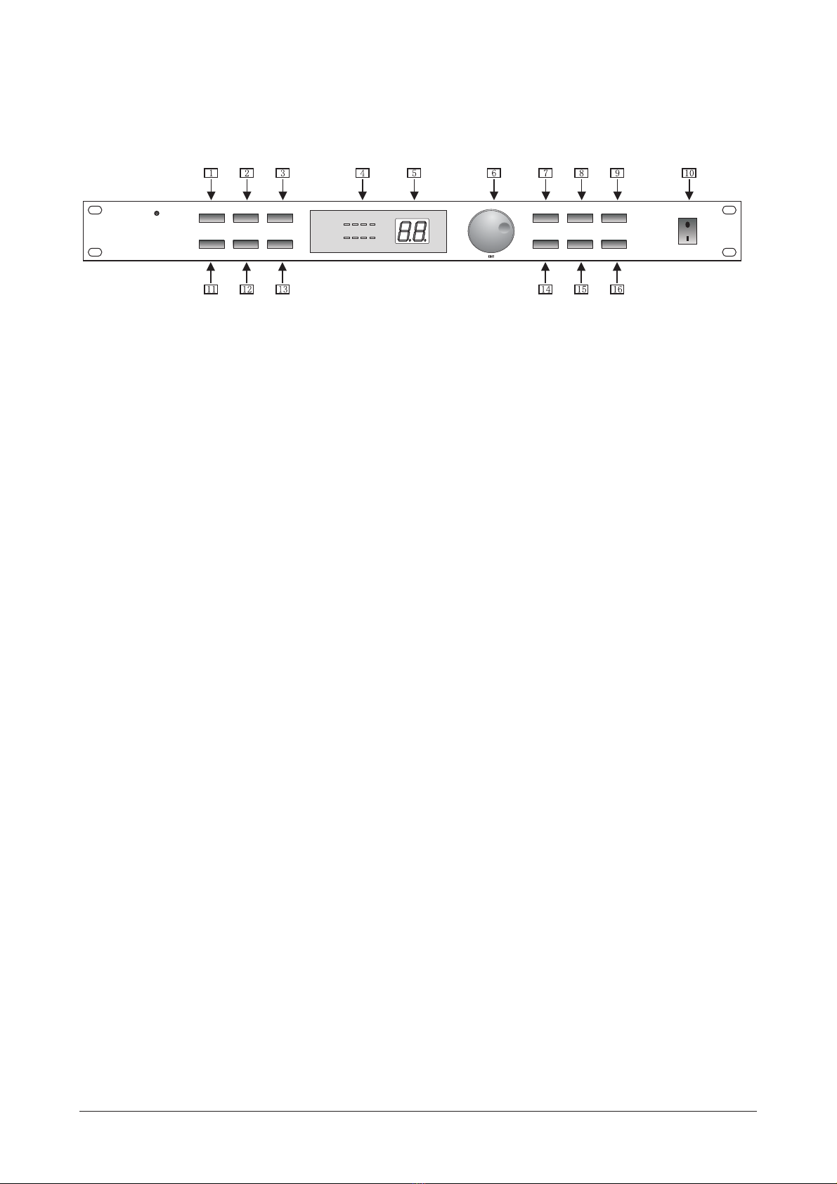
1. The Front Panel
1) Setup Button- <Program/Data>This button is used to select Configuration mode. Once pressed, use the
wheel to select a different effect configuration for the selected program.
2)Parameter 1/Predelay <Program/Data>-This button selects parameter 1 for editing in conjunction with the
wheel. It is also the Predelay parameter of the Reverb effect.
3)Parameter 2/Decay- <Program/Data>This button selects parameter 2 for editing in conjunction with the
wheel. It is also the Decay parameter of the Reverb effect.
4)Input Meter/Effect Display-In Program mode, this meter displays the input signal entering the unit. In Edit
mode, it will indicate which effect is being used.
5)Number Display-In Program mode, this number display will indicate program number(decimal point indicates
a user program). In Edit mode, the display will indicate effects and parameter values.
6)Program/Data Wheel-In Program mode, this wheel is used to change programs and when the unit is in Edit
mode it is used to select effects and change parameter.
7)Program Button-This button returns the DS100 to program mode when pressed.
8)Engine A- <Program/This button selects the Engine A effect module. Once this button is pressed, use the
-Data> wheel to change the effect used in this module.
9)Bypass-This button is used to Bypass all of the digital effects in the DS100 and allow the original dry signal
to pass through the DS100.
10)Power on/off.
11)EQ/Gate- This button(in conjunction with the four parameter buttons) are used to adjust the three band EQ
and Noise gate threshold and release. Press once to select the EQ and press twice to select the
noise gate.
12)Parameter 3/Damping- <Program/Data>This button selects parameter 3 for editing in conjunction with the
wheel. It is also the Damping parameter of the Reverb effect.
13)Parameter 4/Level- <Program/Data>This selects parameter 4(level) for editing in conjunction with the
wheel.
14)Mix/MIDI-This button is used to turn the Dry signal path On and Off and select the MIDI channel that
Page 4
POWER
DUAL ENGINE
MULTI-EFFECTOR
DIGISYNTHETIC
D 100S
SETUP
EQ/GATE
PARAM1 PARAM2
PARAM3 PARAM4
PROGRAM
MIX/MIDI
ENGINE A
ENGINE B
BYPASS
STORE
24 BIT DUAL ENGINE MULTI-EFFECTOR
48 KHZ SAMPLING RATE
CLIP
MOD
PITCH
DELAY REVERB OTHER
ENGINE A
ENGINE B
-10 -20 -30
-10 -20 -30
CLIP

program change information is received on.
15)Engine B- <ProThis button selects the Engine B effect module. Once this button has been pressed, use the
-gram/Data> wheel to change the effect used in the module.
16)Store Button-This button is used to store program modifications in the DS100.
2. The Rear Panel
LEFT IN LEVELRIGHT IN LEVEL
LEFT/MONO IN
RIGHT IN
LEFT/MONO OUT
RIGHT OUT
ALL INPUTS & OUTPUTS
FULLY BALANCED
TIP/PIN2
RING/PIN3
SLEEVE/PIN1
SERIAL NUMBER
DATE CODE
160-250VAC: T125mA
REPLACE WITH SAME TYPE FUSE AND RATING
FUSE:
ATTENTION:
RISK OF ELECTRIC SHOCK
DO NOT OPEN THE COVER OR BACK
20dB
4dB
FOOTSWITCHMIDI IN
20dB
4dB
1)AC Line Input-This is the AC adapter receptacle. Before you connect the unit, please make sure that the
displayed voltage corresponds to your Mains supply.
2)MIDI IN-This MIDI jack is used for receiving MIDI program change and CC information.
3)Footswitch Jack-This Jack is used for the insertion of the Digitech FS-300 footswitch that will control pro
-gram changes and Bypass the digital effects of the DS100.
4)Right Output-This is the DS100's right audio output. Use both left and right outputs to take advantage of
stereo effects.
5)Right Input Level-This knob controls the level of signal entering the DS100 from right. For optimal perfor
-mance, set this level so the Input level indicators(located on the front panel) occasionally
light the red LEDs.
6)Right Input-This is the Right Input jack for the DS100 that when used with Left input will preserve stereo
imaging.
7)Left/Mono Input-This Input jack is used for the Left or Mono input. When only the Left input jack is used,
the signal is sent to both Left and Right DS100 inputs.
8)Left Input Level-This knob controls the level of signal entering the DS100 from left. For optimal performance,
set this level so the Input level indicators(located on the front panel) occasionally light the
red LEDs.
9)Left/Mono Input-This Input jack is used for the Left or Mono input. When only the Left input jack is used,
the signal is sent to both Left and Right DS100 inputs.
3. Operation and Editing
This section will provide you with ll of the information necessary to get the most out of your DS100.
3.1 Program Mode
Page 5

When the DS100 is in program mode, you can move from one program to the next by either using the <Program
/Data> wheel, the optional Digitech FS-300 footswitch or incoming MIDI program change commands from
another device such as a sequencer or keyboard.
When the DS100 is in edit mode and you wish to abort and return to program mode, simply press the <Program>
button.
3.2 Storing Changes
When a program has been modified, the program number will blink in the number display when the unit is in
program mode. To store changes, press the button once. The display alternates between and the<Store>
user program location to be stored to. This simply means that DS100 is now giving you the option to store this
modified version of the program as a user program at any number from 1 to 99. At this point, you may use the
<Program/Data> wheel to change the storing position to another program number. When the target preset
location (shown in the display) is correct, press the button once again. The display will momentarily<Store>
read:-- indicating that the modified program is being stored.
3.3 Selecting Effect Configurations
The DS100 provides you with five different effect configurations that allow you ultimate flexibility and
versatility in effect routing.
Effect Module Size
Effect Configuration 1 uses one effect module because both processing engines are combined for maximum
processing power. This larger module allows you to have longer delay times and more dense sounding reverbs.
Effect configurations 2-5 use size effect modules which allow you to use two effects per program.Half
To select any one of these five different configurations, simply perform the following procedure:
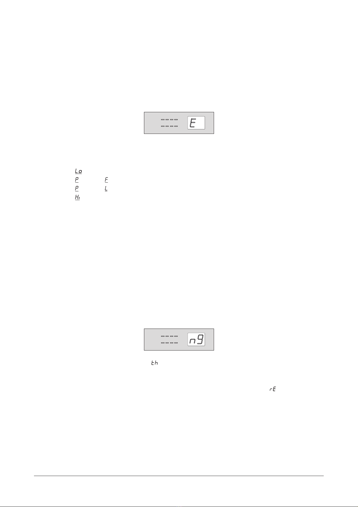
Press the button and the display will briefly read: indicating that you are in the configuration<Config>
select mode and now the display will appear something like this:
Now turn the wheel until the desired configuration appears ( - ) in the display.<Program/Data>
To exit the Effect configuration menu, simply press the button where the display will flash the<Program>
program number until the program change is stored or until you change to the next program.
3.4 Adjusting the Dry Path Global Mix
This editing procedure will allow you to globally turn a Dry signal path Off for use with a mixing consoles'
effects sends or On for use with single instrument input signals(such as guitar, saxophone and others). The
procedure is as follow:
Page 6
24 BIT DUAL ENGINE MULTI-EFFECTOR
48 KHZ SAMPLING RATE
CLIP
MOD
PITCH
DELAY REVERB OTHER
ENGINE A
ENGINE B
-10 -20 -30
-10 -20 -30
CLIP

To edit the Dry signal within the effect configuration of the DS100(turning it On or Off), press the <Mix/MIDI>
button once and the display will briefly read: indicating the dry path mix and then , indicating that the
Dry signal is on. If you wish to turn the dry path off, simply turn the wheel counter clockwise<Program/Data>
and the display will now read:
This now indicates that the Dry signal has been turned Off creating a 100% Wet signal globally in the DS100.
To exit this mode, press the button.<Program>
Note: The Dry path will automatically be turned off when either a Tremolo, Panner, Vocoder, Compressor,
Rotary Speaker or Reverse Reverb effect is used in a program, since the dry signal is already included
in these effects.
3.5 Selecting the MIDI Channel and MIDI CC Information
To select the MIDI channel in which the DS100 receives program change information, from Program mode,
press the button twice and the display will briefly read: (this indicates MIDI channel mode),<Mix/MIDI>
followed by:
Now turn the wheel to select the desired MIDI channel. The options for the MIDI channel<Program/Data>
selection ranges from: - , and (Off).
MIDI program change numbers will be as follows:
1-99 = Programs
100 = Effects Bypass
101 = Exit Effects Bypass
102 = Effect Bypass Toggle
103 = Selects User Program Bank
104 = Selects Factory Program Bank
To exit the MIDI channel menu, press the button.<Program>
3.6 MIDI CC Information
The DS100 will also receive MIDI CC information for parameter control of the following parameter:
- is turned On or Off by MIDI CC number - CC 7.Dry Level
3.7 EQ and Noise Gate Adjustments
This editing function allows you to make key EQ and Noise gate modifications to custom tailor your sound for
each program. The procedure for both is as follows:
Page 7
24 BIT DUAL ENGINE MULTI-EFFECTOR
48 KHZ SAMPLING RATE
CLIP
MOD
PITCH
DELAY REVERB OTHER
ENGINE A
ENGINE B
-10 -20 -30
-10 -20 -30
CLIP
24 BIT DUAL ENGINE MULTI-EFFECTOR
48 KHZ SAMPLING RATE
CLIP
MOD
PITCH
DELAY REVERB OTHER
ENGINE A
ENGINE B
-10 -20 -30
-10 -20 -30
CLIP
- EQ - Range for the Low EQ is from -12 to +12 dB.
- arametric requency - Range for the Parametric Frequency is from 1 to 26.
- arametric evel - Range for the Parametric Level is from -12 to +12 dB.
- EQ - Range for the High EQ is from -12 to +12 dB.
To modify any one these four parameters, simply press the respective button and then turn the
wheel.
Once the modifications are done, remember to store any changes and press the button to return
to Program mode.
The DS100 gives you the ability custom tailor the Noise gate parameters (Threshold and Release) for each pro
-gram by performing the following procedure:
Press the button twice. The display will appear something like this, indicating that you are in No
-ise Gate edit mode:
Now press the button and will appear prompting you to adjust the Noise gate Threshold
by turning the wheel. The range for the Noise gate Threshold is from Off, 99 to 0.
To adjust the Noise Gate Release , press the and the display will read: , prompting you
to use the wheel to adjust the Noise Gate Release parameter. Release range is from 1 to 10.
Once all Noise gate modifications have been made, remember to store the changes and press the
button to return to program mode.
Adjusting the EQ
<EQ/Gate>
<Parameter 1-4>
The DS100 offers a three band EQ with Lo EQ, Parametric Frequency, Parametric Level and Hi EQ parameters.
To adjust any one of these four, perform the following procedure:
Press the button once and the display will briefly read:
Now to make adjustments to the four different EQ parameters use the buttons. Parameter
and value range for each is listed below.
Because of its processing power, the DS100 gives you two Engine modules that are fully programmable. The
following section explains the simple procedure for Engine A and B editing.
Parameter 1
Parameter 2
Parameter 3
Parameter 4
<Parameter>
<Program/Data>
<Program>
Adjusting the Noise Gate
<EQ/Gate>
<Parameter 1>
<Program/Data>
<Parameter 2 >
<Program/Data>
<Program>
3.8 Editing Engine A and B Modules
Page 8
24 BIT DUAL ENGINE MULTI-EFFECTOR
48 KHZ SAMPLING RATE
CLIP
MOD
PITCH
DELAY REVERB OTHER
ENGINE A
ENGINE B
-10 -20 -30
-10 -20 -30
CLIP
24 BIT DUAL ENGINE MULTI-EFFECTOR
48 KHZ SAMPLING RATE
CLIP
MOD
PITCH
DELAY REVERB OTHER
ENGINE A
ENGINE B
-10 -20 -30
-10 -20 -30
CLIP

Selecting and Editing Effects
From Program mode, press either the or button. The current type of effect will light<Engine A> <Engine B>
the corresponding LED in the effect display and it's two letter abbreviation will appear in the number display
something .
Now turn the wheel to select the effect to be used. The effect display's abbreviation will ]<Program/Data>
change as the new effects are selected.
Once the effect to be used has been selected, you can use the edit buttons to modify the<Parameter 1-4>
parameters of the selected effect.
For a complete list of the effects available and their respective names, please see Section 3 on pages 13-16.
Once all of the edits have been made to the selected program, make sure to store any changes and then press
the button to return to the Program mode.<Program>
4. Effects and Parameters
This section provides you with a detailed description of the Digital effects in the DS100 and their parameters
and values. A complete list of these effects is also printed on the top of the DS100.
4.1 Modulation Effects
Effect Name Parameter 1 Parameter 2 Parameter 3 Parameter 4
Cborus- Speed- Depth- Delay- Level-
Flange- Speed- Depth- Feedback- Level-
Pbaser- Speed- Depth- Feedback- Level-
Tremolo- Speed- Depth- N/A Level-
Panner- Speed- Depth- N/A Level-
Rotary Speaker- Speed- Type- X-oveer Freq- Level-
The Modulation effects menu offers a vast list of modulating effects ranging from Chorus to a Rotary Speaker
simulator. These modulation effects are ideal producing lush sounding effects that can add dimension to any
signal. The parameters and values for the modulation effects are as follows:
Speed The Speed parameter controls the speed of the modulation in the effect.
Range is from 0 to 99 or Slow to Fast.
Depth This parameter controls the amount of depth of the modulation effect.
Range is from 0 to 40.
Delay This parameter controls the delay time within the modulation effect.
Range is from 0 to 40 milliseconds.
Feedback This parameter controls the amount of regeneration feedback in the
modulation effect. Range is from 0 to 97%.
Page 9

Type This parameter selects between six different modulation extremes.
Cross-over Frequency This parameter selects the frequency where the signal is split between
the Rotor and the Horn. Settings are1-4.
Level This parameter allows you to set the overall level of the selected effect.
Range is from 0 to 99.
4.2 Pitch Shifters
Effect Name Parameter 1 Parameter 2 Parameter 3 Parameter 4
Pitch Sbift- Sbift- Tracking- N/A Level-
Detuner- Detune Amt- N/A N/A Level-
The Pitch Shifting effects menu includes a Pitch Shifting effect that allows you to shift the original signal to
help produce Harmony effects, while the Detuner effect will help you thicken up any signal to add dimension to
your sound. Parameters for the Pitch Shifting Effects are as follow:
Shift This parameter sets how far the signal is shifted. Range is from -12 to +24 semi-tones.
Tracking This lets you select the tracking level of the Pitch shifter effects. Range is from 1 to 3.
Detune Amount This parameter sets the amount of Detune in the effect. Range is from-12 to +12 cents.
Level This parameter allows you to set the overall level of the selected effect. Range is from
0to99.
4.3 Delay
Effect Name Parameter 1 Parameter 2 Parameter 3 Parameter 4
Mono Delay- Delay Coarse- Delay Fine- Feedback- Level-
Stereo Delay- Delay Coarse- Delay Fine- Feedback- Level-
Ping Pong- Delay Coarse- Delay Fine- Feedback- Level-
Karaoke- Delay Time- N/A Repeats- Level-
The DS100 offers three different Delay effects including: Mono, Stereo and Ping Pong, offering ultimate flexi
-bility in digital delay applications. The DS100 also offers a Karaoke delay effect. The parameters and their
values are as follows:
When Delay effects are use in Effect Configuration 1(which is a Whole effect module), longer delayNote:
times are available. These Delay time differences are marked W(Whole) and H(Half) in the Maximum
delay time chart on the following page.
Maximum Delay times
D-1 (Half=1000 milliseconds and Whole=2000 milliseconds)
Page 10
(Half=700 milliseconds and Whole=1000 milliseconds)D-2
D-3 (Half=1000 milliseconds and Whole=2000 milliseconds)
Delay Coarse This parameter controls the length of the Delay Coarse time Range is from.
1 (which equals 100 milliseconds) to 2. 0 (which equals 2 seconds).
Delay Fine This parameter controls the length of the Delay Fine time. Range is from
0 to 99 milliseconds.
Delay Time This parameter controls the length of the Delay Time that is offered in
the Karaoke. Delay Time settings are 1-5.
Feedback This parameter controls the amount of delay repeats in the delay effect.
Range is from 0 to 99% and repeat-hold ( rh ).
Repeat This parameter controls the amount of delay repeats in the D-4 Karaoke
Effect. Range is from 1 to 10.
Level This parameter allows you to set the overall level of the selected effect.
Range is from 0 to 99.
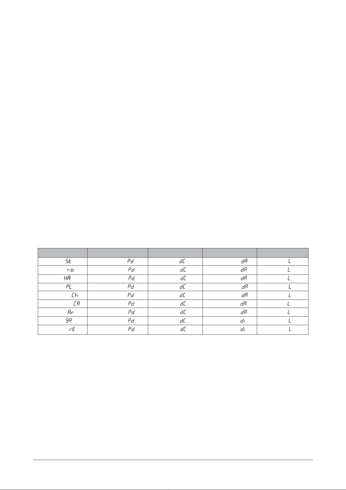
4.4 Reverb
Effect Name Parameter 1 Parameter 2 Parameter 3 Parameter 4
Stage- Predelay- Decay- Damping- Level-
Room- Predelay- Decay- Damping- Level-
Hall- Predelay- Decay- Damping- Level-
Plate- Predelay- Decay- Damping Level--
Chamber- Predelay- Decay- Damping- Level-
Cathedral- Predelay- Decay- Damping- Level-
Arena- Predelay- Decay- Damping- Level-
Gated- Predelay- Decay- Diffusion- Level-
Reverse- Predelay- Decay- Diffusion- Level-
Reverb is the perfect effect for adding dimension to any recording or live application where you need to emulate
the size and shapes of different types of rooms. The following explains the parameters that are available in the
Reverb effects.
Note: When Reverb effects are used in Effect Configuration 1(which is a Whole effect module) large and more
dense sounding Reverbs can be obtained.
Pre Delay This parameter controls the length of time before the reverb reflections are heard.
Range is from 0 to 99 ms.
Decay This parameter controls the decay length(reverb time) of the reverberation. Range
is from 1 to 10.
Page 11

Damping This parameter controls the high frequency decay of the reverb effect and
ranges from 1 to 10.
Diffusion This parameter controls the reverb smoothness and ranges from 1 to 10.
Level This parameter allows you to set the overall level of the selected effect.
Range is from 0 to 99.
4.5 Other Effects
Effect Name Parameter 1 Parameter 2 Parameter 3 Parameter 4
Ring Modulator- Frequency- N/A N/A Level-
Compressor- Threshold- Ratio- Attack- Gain-
Vocoder- Sibliance- Type- N/A Level-
The DS100 also offers and additional menu of hard to find effects including: a effect which takes aVocoder
vocal signal (using the Left input) and superimposes it onto another input signal such as a keyboard(using the
Right input) to produce a vocal effect that sounds more robotic than human. This menu also provides you with
a that can produce mathematically-based harmonic effects. And last but not least, we have alsoRing modulator
included a state-of-the-art that is ideal for making any signal stand out with the right amount ofCompressor
compression. The parameters for these effects are as follows:
Frequency This parameter sets the modulation frequency of the Ring Modulator effect.
Range is from 1 to 99.
Threshold This parameter sets threshold level of the compressor. Range is 60 to 0.
Ratio This parameter sets the compressor ratio. Range is from 1 to 19 and .
Attack This parameter controls the attack time of the compressor. Range is from 1
to 10.
Gain This parameter allows you to select the overall gain of the selected effect.
Range is from -19 to 20.
Type This parameter allows you to select the different types of Vocoder effect setting
in the DS100. Types include:1-5.
Sibilance This parameter allows you to set the amount of Essing that is passed through
the Vocoder effect. Range is from 0 to 99.
Level This parameter allows you to set the overall level of the selected effect. Range
is from 0 to 100.
5. Appendix
This section provides you with information to Factory Reset the DS100, a Specification page and a Program list.
Page 12

5.1 Resetting the DS100
This procedure will allow you to perform a complete factory reset on the DS100.
Warning-All previous program information will be deleted when the reset is performed
To perform a factory reset on the DS100, simply press and hold the button while applying power<Program>
to the unit and the display will briefly read:--and then appear like this:
Now release the button and immediately press the button and the DS100 will proceed<Program> <Config>
to reset. In the process of resetting, the DS100 will briefly display the current software version number and
then return to program mode.
Page 13
24 BIT DUAL ENGINE MULTI-EFFECTOR
48 KHZ SAMPLING RATE
CLIP
MOD
PITCH
DELAY REVERB OTHER
ENGINE A
ENGINE B
-10 -20 -30
-10 -20 -30
CLIP

6. Specifications
Frequency Response:
Signal-to-Noise Ratio:
THD:
Memory Allocations:
Sampling Rate:
A/D Converter:
D/A Converter:
External Signal Path Width:
Internal Signal Path Width:
Multiplier Size:
Inputs:
Outputs:
MIDI:
Power Consumption:
Power Requirements:
Net Weight:
20-20kHz+/-0.5dB
98dB(A-Weighted ref=Max signal 22kHz measurement bandwidth)
Less than 0.008%
99 User-99 Factory Programs
48kHz
24 bit,128 oversampled
24 bit, 128 oversampled
24 bits
24 bits
24 bits x 24 bits
Stereo(2)1/4" Unbalanced-Max In +18 dBu
Stereo(2)1/4"Impedance Balance- Max +18 dBu
MIDI In Program Changes
5 watts
Included external power supply(PS 750)
2kg
Page 14
All technical specifications in DIGISYNTHETIC products are subject to changes for product improvement
with withoutor NOTICE.
Table of contents
Other DIGISYNTHETIC Recording Equipment manuals


Popular Recording Equipment manuals by other brands

PS Engineering
PS Engineering PMA8000B--MP3 Installation and operation manual

ETC
ETC EchoAccess installation guide

lag
lag HyVibe H1 user manual

Adcom
Adcom GSP-560 owner's manual

Clear-Com
Clear-Com CCI-22 instruction manual

L3 Communications
L3 Communications Targa 4 Series Technical reference and installation guide


 user manual")


