FOR-A MFR-9SDIR User manual

MFR-9SDIR
MFR-9SDOR
1st Edition
OPERATION
MANUAL

2
Upon Receipt
Optional cards for MFR-4000R and MFR-6000R are fully inspected and adjusted prior to shipment.
Check your received items against the packing lists below. Check to ensure no damage has occurred
during shipment. If damage has occurred, or items are missing, inform your supplier immediately.
◆Option
ITEM
QTY
REMARKS
MFR-9SDIR
MFR-9SDOR
1
Installation Guide
1
This manual.

3
Prior to Starting
MFR-9SDIR is an input card for MFR-4000R/MFR-6000R units.
MFR-9SDOR is an output card for MFR-4000R/MFR-6000R units.
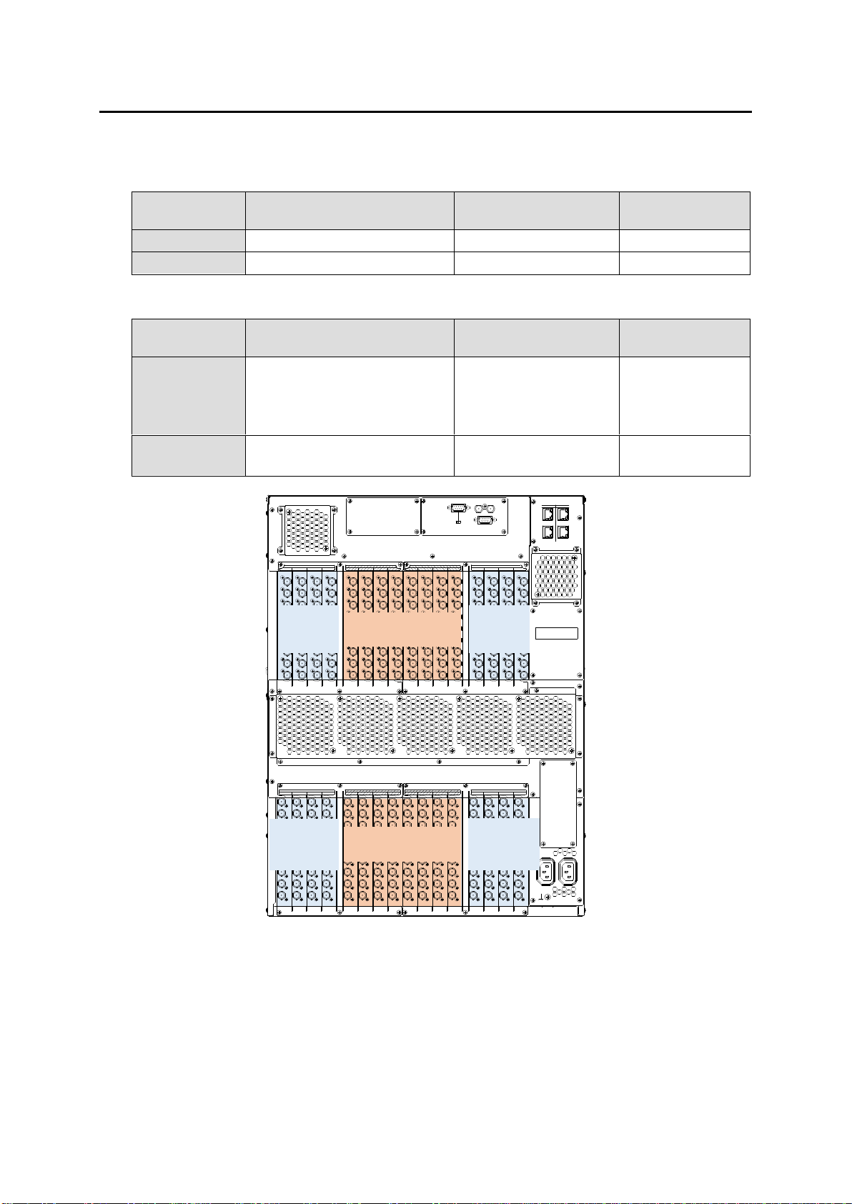
◆Available Slots and Number for MFR-4000R Input / Output Cards
Slot
Slot number
Installable cards
Installable number
of cards
Input slot
No.01-08 (INPUT1-8)
MFR-9SDIR
Up to 8 cards
Output slot
No.09-16 (OUTPUT1-8)
MFR-9SDOR
Up to 8 cards
◆Available Slots and Number for MFR-6000R Input / Output Cards
Slot
Slot number
Installable cards
Installable number
of cards
Input slot
No. 01-04 (INPUT1-4)
No. 13-16 (INPUT5-8)
No. 17-20 (INPUT9-12)
No. 29-32 (INPUT13-16)
MFR-9SDIR
Up to 16 cards
Output slot
No. 05-12 (OUTPUT1-8)
No. 21 -28 (OUTPUT9-16)
MFR-9SDOR
Up to 16 cards
232C 422
SERIAL
REF IN
ALARM
CPU1CPU2
PC-LAN
PC-LAN MFR-LAN
MFR-LAN
INPUTOUTPUT 5 6 7 85 6 7 8
OUTPUTINPUT
1 2 3 4 1 2 3 4
INPUT INPUTOUTPUT OUTPUT
AC100-240V 50/60 Hz IN
12
13 14 15 1613 14 15 16910 11 12910 11 12
1 1 1 1 1 1 1 1 1 1 1 1 1 1 1 1
1 1 1 1 1 1 1 1 1 1 1 1 1 1 1 1
2 2 2 2 2 2 2 2 2 2 2 2 2 2 2 2
2 2 2 2 2 2 2 2 2 2 2 2 2 2 2 2
3 3 3 3 3 3 3 3 3 3 3 3 3 3 3 3
3 3 3 3 3 3 3 3 3 3 3 3 3 3 3 3
4 4 4 4 4 4 4 4 4 4 4 4 4 4 4 4
4 4 4 4 4 4 4 4 4 4 4 4 4 4 4 4
5 5 5 5 5 5 5 5 5 5 5 5 5 5 5 5
5 5 5 5 5 5 5 5 5 5 5 5 5 5 5 5
6 6 6 6 6 6 6 6 6 6 6 6 6 6 6 6
6 6 6 6 6 6 6 6 6 6 6 6 6 6 6 6
7 7 7 7 7 7 7 7 7 7 7 7 7 7 7 7
7 7 7 7 7 7 7 7 7 7 7 7 7 7 7 7
8 8 8 8 8 8 8 8 8 8 8 8 8 8 8 8
8 8 8 8 8 8 8 8 8 8 8 8 8 8 8 8
9 9 9 9 9 9 9 9 9 9 9 9 9 9 9 9
9 9 9 9 9 9 9 9 9 9 9 9 9 9 9 9
Output 9-16
(Slot No.21-28)
Output 1-8
(Slot No.05-12)
Input 1-4
(Slot
No.01-04)
Input 5-8
(Slot
No.13-16)
Input 13-16
(Slot
No.29-32)
Input 9-12
(Slot
No.17-20)

4
1. Matrix Size Chart
1-1. MFR-4000R
◆Standard SDI Signal Routing
Matrix size varies depending on the number of installed MFR-9SDIR and MFR-9SDOR cards as
shown below. (72 x 72 to 9 x 9)
Number of cards: MFR-9SDOR
8
7
6
5
4
3
2
1
Number of cards:
MFR-9SDIR
8
72 x 72
72 x 63
72 x 54
72 x 45
72 x 36
72 x 27
72 x 18
72 x 9
7
63 x 72
63 x 63
63 x 54
63 x 45
63 x 36
63 x 27
63 x 18
63 x 9
6
54 x 72
54 x 63
54 x 54
54 x 45
54 x 36
54 x 27
54 x 18
54 x 9
5
45 x 72
45 x 63
45 x 54
45 x 45
45 x 36
45 x 27
45 x 18
45 x 9
4
36 x 72
36 x 63
36 x 54
36 x 45
36 x 36
36 x 27
36 x 18
36 x 9
3
27 x 72
27 x 63
27 x 54
27 x 45
27 x 36
27 x 27
27 x 18
27 x 9
2
18 x 72
18 x 63
18 x 54
18 x 45
18 x 36
18 x 27
18 x 18
18 x 9
1
9 x 72
9 x 63
9 x 54
9 x 45
9 x 36
9 x 27
9 x 18
9 x 9

5
1-2. MFR-6000R
◆Standard SDI Signal Routing
Matrix size varies depending on the number of installed MFR-9SDIR and MFR-9SDOR cards as
shown below. (144 x 144 to 9 x 9)
Number of cards: MFR-9SDOR
16
15
14
13
12
11
10
9
8
7
6
5
4
3
2
1
Number of cards: MFR-9SDIR
16
144
x
144
144
x
135
144
x
126
144
x
117
144
x
108
144
x
99
144
x
90
144
x
81
144
x
72
144
x
63
144
x
54
144
x
45
144
x
36
144
x
27
144
x
18
144
x
9
15
135
x
144
135
x
135
135
x
126
135
x
117
135
x
108
135
x
99
135
x
90
135
x
81
135
x
72
135
x
63
135
x
54
135
x
45
135
x
36
135
x
27
135
x
18
135
x
9
14
126
x
144
126
x
135
126
x
126
126
x
117
126
x
108
126
x
99
126
x
90
126
x
81
126
x
72
126
x
63
126
x
54
126
x
45
126
x
36
126
x
27
126
x
18
126
x
9
13
117
x
144
117
x
135
117
x
126
117
x
117
117
x
108
117
x
99
117
x
90
117
x
81
117
x
72
117
x
63
117
x
54
117
x
45
117
x
36
117
x
27
117
x
18
117
x
9
12
108
x
144
108
x
135
108
x
126
108
x
117
108
x
108
108
x
99
108
x
90
108
x
81
108
x
72
108
x
63
108
x
54
108
x
45
108
x
36
108
x
27
108
x
18
108
x
9
11
99
x
144
99
x
135
99
x
126
99
x
117
99
x
108
99
x
99
99
x
90
99
x
81
99
x
72
99
x
63
99
x
54
99
x
45
99
x
36
99
x
27
99
x
18
99
x
9
10
90
x
144
90
x
135
90
x
126
90
x
117
90
x
108
90
x
99
90
x
90
90
x
81
90
x
72
90
x
63
90
x
54
90
x
45
90
x
36
90
x
27
90
x
18
90
x
9
9
81
x
144
81
x
135
81
x
126
81
x
117
81
x
108
81
x
99
81
x
90
81
x
81
81
x
72
81
x
63
81
x
54
81
x
45
81
x
36
81
x
27
81
x
18
81
x
9
8
72
x
144
72
x
135
72
x
126
72
x
117
72
x
108
72
x
99
72
x
90
72
x
81
72
x
72
72
x
63
72
x
54
72
x
45
72
x
36
72
x
27
72
x
18
72
x
9
7
63
x
144
63
x
135
63
x
126
63
x
117
63
x
108
63
x
99
63
x
90
63
x
81
63
x
72
63
x
63
63
x
54
63
x
45
63
x
36
63
x
27
63
x
18
63
x
9
6
54
x
144
54
x
135
54
x
126
54
x
117
54
x
108
54
x
99
54
x
90
54
x
81
54
x
72
54
x
63
54
x
54
54
x
45
54
x
36
54
x
27
54
x
18
54
x
9
5
45
x
144
45
x
135
45
x
126
45
x
117
45
x
108
45
x
99
45
x
90
45
x
81
45
x
72
45
x
63
45
x
54
45
x
45
45
x
36
45
x
27
45
x
18
45
x
9
4
36
x
144
36
x
135
36
x
126
36
x
117
36
x
108
36
x
99
36
x
90
36
x
81
36
x
72
36
x
63
36
x
54
36
x
45
36
x
36
36
x
27
36
x
18
36
x
9
3
27
x
144
27
x
135
27
x
126
27
x
117
27
x
108
27
x
99
27
x
90
27
x
81
27
x
72
27
x
63
27
x
54
27
x
45
27
x
36
27
x
27
27
x
18
27
x
9
2
18
x
144
18
x
135
18
x
126
18
x
117
18
x
108
18
x
99
18
x
90
18
x
81
18
x
72
18
x
63
18
x
54
18
x
45
18
x
36
18
x
27
18
x
18
18
x
9
1
9
x
144
9
x
135
9
x
126
9
x
117
9
x
108
9
x
99
9
x
90
9
x
81
9
x
72
9
x
63
9
x
54
9
x
45
9
x
36
9
x
27
9
x
18
9
x
9

6
2. [MFR-4000R] I/ O Card Installation / Replacement
IMPORTANT
Contact FOR-A agent or service center for I/O Card installation and replacement work since such
work should only be conducted by qualified technical personnel.
2-1. How to Install a New Card
The following procedure shows how to install an output card into OUTPUT1 slot.
1. Unfasten to remove four fixing screws along the front panel as shown and detach the front
panel.
2. Loosen the four thumbscrews and detach the card stopper (Bottom).
3. Loosen the two thumbscrews on the card stopper (Top).
4. Loosen the three binding screws and detach the card stopper (Top).
5. Detach the OUTPUT1 slot blank panel.
6. Insert a new card firmly into the OUTPUT1 slot.
* Confirm the slot number and
direction before card insertion.
Point the connector
upward.
(2)
(3)
Card stopper (Bottom)
OUTPUT1 slot
(2)
(2)
(2)
(3)
(4)
Card stopper (Top)
MFR
MFR-4000
ROUTING SWITCHER R
POWER CPU1 CPU2
POWER 1 POWER 2
ON
OFF OFF
ON

7
7. Re-install the card stopper (Bottom) removed in Step 2.
Hook the four hooks into the holes on the side of the card rail.
8. Make sure that the four hooks are hooked on the rail bracket of the unit and fasten the four
thumbscrews.
9. Re-install the card stopper (Top) removed in Step 4. Hook the latches into the spaces on
either side, and fasten the two thumbscrews.
10.Fasten the three binding screws.
Holes on the side of
the card rail
Four hooks

8
11.Turn the OUTPUT1 slot ON using [SETTING > SLOT SHUTDOWN] menu in Menu display.
See MFR-4000R Operation Manual Sec. 4-2-2. “Turning ON/OFF an Input/ Output Card” for
details.
12.Verify that LEDs on the card installed into OUTPUT1 light up.
13.Re-install the front panel.
A new card installation is now complete.
To use the input/ output of the installed card, add assignment settings in the Source Assignment
screen and Destination Assignment screen in the Web GUI.

9
2-2. How to Replace a Card
The following procedure shows how to replace a card in INPUT1 slot to a new input card.
1. Detach all the BNC cables connected to the INPUT1 connector ports.
2. Unfasten to remove four fixing screws along the front panel and detach the front panel.
3. Shutdown the INPUT1 slot in [SETTING > SLOT SHUTDOWN] menu of Menu Display. See
Sec. 4-2-2. “Turning ON/OFF an Input/ Output Card” for details.
4. Remove the card stoppers (Top) and (Bottom). (See Sec. 2-1. “How to Install a New Card”
for details.)
5. Grab the INPUT1 slot card handle and slowly remove (pull out) the card.
6. Insert a new card firmly into the INPUT1 slot.
*Confirm the slot number and direction before card insertion. (See Step 4. in Sec. 2-1. “How to
Install a New Card.”)
7. Re-install the card stoppers (Top) and (Bottom) removed in Step 4.
8. Turn the INPUT1 slot ON using [SETTING > SLOT SHUTDOWN] menu in Menu display.
(See MFR-4000R Operation Manual Sec. 4-2-2. “Turning ON/OFF an Input/ Output Card” for
details.)
9. Verify that LEDs on the card installed into INPUT1 light up.
10. Re-install the front panel.
The card replacement is now complete.
INPUT1 slot
CPU 2
CP U 1
ALARM
SER IA L
232C 422
REF IN
AC1 0 0 - 2 40 V 5 0 /6 0 Hz IN
12
OUTPUT
1 2 3 4 5 6 7 8
INPUT
1 2 3 4 5 6 7 8
1
2
3
4
5
6
7
8
9
1
2
3
4
5
6
7
8
9
1
2
3
4
5
6
7
8
9
1
2
3
4
5
6
7
8
9
1
2
3
4
5
6
7
8
9
1
2
3
4
5
6
7
8
9
1
2
3
4
5
6
7
8
9
1
2
3
4
5
6
7
8
9
111 11111
2 2 2 2 2 2 2 2
33333333
4 4 4 4 4 4 4 4
55555555
6 6 6 6 6 6 6 6
77777777
8 8 8 8 8 8 8 8
99999999
Card stopper (Bottom)
Card stopper (Top)
INPUT1 slot

10
3. [MFR-6000R] I/ O Card Installation / Replacement
3-1. How to Install a New Card
The following procedure shows how to install an output card into OUTPUT1 slot.
1. Unfasten to remove four fixing screws along the front panel as shown and detach the front
panel.
2. Loosen the four thumbscrews and detach the card stopper (B).
3. Loosen the screw on the left side of the card stopper (A) and detach the card stopper (A).
4. Detach the OUTPUT1 slot blank panel.
5. Insert a new card firmly into the
OUTPUT1 slot.
* Confirm the slot number (See the
figure on page 3) and direction before
card insertion.
Point the connector down.
Slot 1-16
Slot 17-32
Point the connector
up.
(3)
OUTPUT1 slot
Card stopper (A)
(2)
(2)
(2)
(2)
Card stopper (B)
MFR
POWER 2
ON
OFF
POWER 1
ON
OFF
POWER
CPU1
CPU2
R
MFR-6000
ROUTINGSW ITCHER

11
6Re-install the card stopper (B) removed in Step 2.
Hook the four hooks into the holes on the side of the card rail.
7. Make sure that the four hooks are hooked on the rail bracket of the unit and fasten the four
thumbscrews.
8. Re-install the card stopper (A) removed in Step 3.
9. Turn the OUTPUT1 slot ON using [SETTING > SLOT SHUTDOWN] menu in Menu display.
See MFR-6000R Operation Manual Sec. 4-2-2. “Turning ON/OFF an Input/ Output Card” for
details.
10.Verify that LEDs on the card installed into OUTPUT1 light up.
11.Re-install the front panel.
A new card installation is now complete.
To use the input/ output of the installed card, add assignment settings in the Source Assignment
screen and Destination Assignment screen in the Web GUI.
(8)
(7)
(7)
(7)
(7)
Holes on the side of
the card rail
Four hooks

12
3-2. How to Replace a Card
The following procedure shows how to replace a card in INPUT9 slot to a new input card.
1. Detach all the BNC cables connected to the
INPUT9 connector ports.
2. Unfasten to remove four fixing screws along the
front panel and detach the front panel.
3. Shutdown the INPUT9 slot in [SETTING > SLOT
SHUTDOWN] menu of Menu Display.
See MFR-6000R Operation Manual Sec. 4-2-2.
“Turning ON/OFF an Input/ Output Card” for details.
4. Remove the card stoppers (A) and (B).
(See Sec. 3-1. “How to Install a New Card” for
details.)
5. Grab the INPUT9 slot card handle and slowly
remove (pull out) the card.
6. Insert a new card firmly into the INPUT9
slot.
*Confirm the slot number (See page 3) and
direction before card insertion.
(See Step 5. in Sec. 3-1. “How to Install a
New Card.”)
7. Re-install the card stoppers (A) and (B)
removed in Step 4.
(See Steps 6. to 8. in Sec. 3-1. “How to
Install a New Card.”)
8. Turn the INPUT9 slot ON using [SETTING
> SLOT SHUTDOWN] menu in Menu
display.
(See MFR-6000R Operation Manual Sec.
4-2-2. “Turning ON/OFF an Input/ Output
Card” for details.)
9. Verify that LEDs on the card installed into
INPUT9 light up.
10. Re-install the front panel.
The card replacement is now complete.
INPUT9 slot
INPUT9 slot
Card stopper (B)
Card stopper (A)


January 19, 2022 Printed in Japan
http://www.for-a.com/
FOR-A COMPANY LIMITED
Head Office 3-8-1 Ebisu, Shibuya-ku, Tokyo 150-0013, Japan
Overseas Division Tel: +81(0)3-3446-3936 Fax: +81(0)3-3445-5116
Japan Branch Offices Osaka/Okinawa/Fukuoka/Hiroshima/Nagoya/Sendai/Sapporo
R&D/Production Sakura Center/Sapporo Center
FOR-A Corporation of America Corporate Office/Service Center
11155 Knott Ave., Suite G, H & I, Cypress, CA 90630, U.S.A.
Tel: +1 714-894-3311 Fax: +1 714-894-5399
FOR-A Corporation of America Northeast Office
1360 Clifton Ave., Clifton, NJ 07012, U.S.A.
Tel: +1 973-220-8471 Fax: +1 714-894-5399
FOR-A Corporation of America Southeast Office
Tel: +1-305-773-7608
FOR-A Corporation of America Support Center
2400 N.E. Waldo Road, Gainesville, FL 32609, U.S.A.
Tel: +1 352-371-1505 Fax: +1 714-894-5399
FOR-A Latin America and the Caribbean Miami Office
Tel: +1 657-600-5759
FOR-A Latin America and the Caribbean Sao Paulo Office
Tel: +55 (0)11-99913-3751
FOR-A Europe S.r.l.
Via Volturno, 37, 20861, Brugherio MB, Italy
Tel: +39 (0)39-916-4811
FOR A UK Limited
Trident Court, 1 Oakcroft Road Chessington, KT9 1BD, U.K.
Tel: +44 (0)20-3044-2935 Fax: +44 (0)20-3044-2936
FOR-A Italia S.r.l.
Via Volturno, 37, 20861, Brugherio MB, Italy
Tel: +39 (0)39-881-086
FOR-A Corporation of Korea
1007, 57-5, Yangsan-ro, Yeongdeungpo-gu, Seoul 07271, Korea
Tel: +82 (0)2-2637-0761 Fax: +82 (0)2-2637-0760
FOR-A China Limited
1618 Huateng Building, No. 302, 3 District, Jinsong, Chaoyang, Beijing 100021, China
Tel: +86 (0)10-8721-6023 Fax: +86 (0)10-8721-6033
FOR-A Middle East Africa Office
Aurora Tower, Office 1407, Dubai Media City, P.O. Box 502688, Dubai, UAE
Tel: +971 (0)4 551 5830 Fax: +971 (0)4 551 5832
FOR-A India Private Limited. Mumbai Office
2nd Floor, Valecha Chambers, Link Road, Andheri (W), Mumbai 400053, India
Tel: +91-(0)22-2673-3623 Fax: +91-(0)22-2639-3415
FOR-A India Private Limited. Delhi Office
8th floor, World Trade Tower, Sector-16, Noida, Uttar Pradesh 201301, India
Tel: +91-(0)12-0423-8674
FOR-A South East Asia Office
Studio 09, Rm. A1, 3/F., Phase 1, Hang Fung Ind. Bldg., 2G Hok Yuen St., Hung Hom, Hong Kong
Tel: +852 2110-1352
This manual suits for next models
1
Table of contents
Other FOR-A Recording Equipment manuals