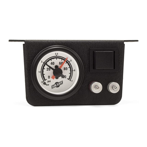
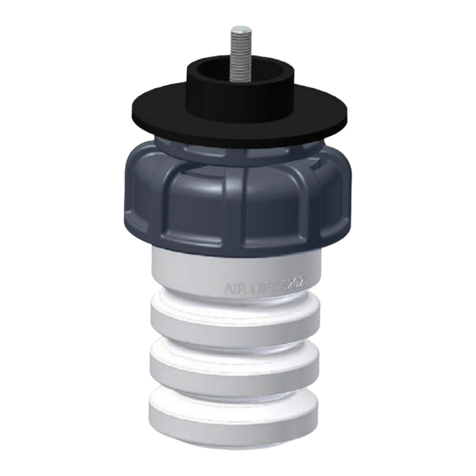
Air Lift RoadTamer 25325 User manual
Other Air Lift Automobile Accessories manuals

Air Lift
Air Lift Load Controller I User manual

Air Lift
Air Lift WirelessAIR 74100EZ User manual

Air Lift
Air Lift 1000 User manual

Air Lift
Air Lift LoadLifter 7500 XL User manual

Air Lift
Air Lift Ride Control 59544 User manual

Air Lift
Air Lift 1000 User manual

Air Lift
Air Lift AirCELL 52205 User manual

Air Lift
Air Lift 57200 User manual

Air Lift
Air Lift loadlifter 5000 User manual

Air Lift
Air Lift loadlifter 5000 User manual

Air Lift
Air Lift RideControl 59540 User manual

Air Lift
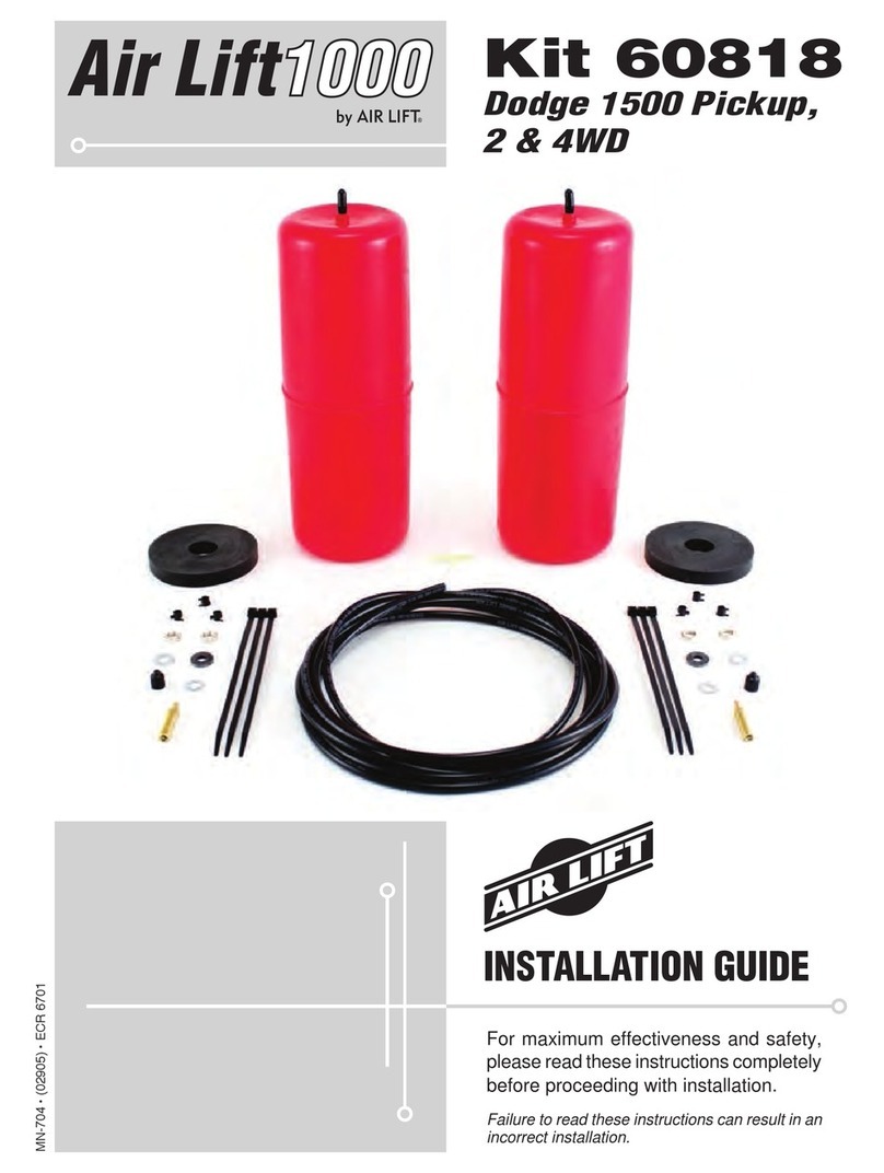
Air Lift Air Lift 1000 60818 User manual

Air Lift
Air Lift LoadLifter 5000 Ultimate User manual

Air Lift
Air Lift loadlifter 5000 User manual

Air Lift
Air Lift 1000 User manual

Air Lift
Air Lift Air Lift 1000 60713 User manual

Air Lift
Air Lift RideControl 59516 User manual

Air Lift
Air Lift LoadLifter 5000 Ultimate User manual

Air Lift
Air Lift Slam Air 59111 User manual

Air Lift
Air Lift LoadLifter 5000 Series User manual
Popular Automobile Accessories manuals by other brands

ULTIMATE SPEED
ULTIMATE SPEED 279746 Assembly and Safety Advice

SSV Works
SSV Works DF-F65 manual

ULTIMATE SPEED
ULTIMATE SPEED CARBON Assembly and Safety Advice

Witter
Witter F174 Fitting instructions

WeatherTech
WeatherTech No-Drill installation instructions

TAUBENREUTHER
TAUBENREUTHER 1-336050 Installation instruction


