Digital Electronics Corporation PL-FF020 User manual

‑1‑
PL‑FF020(フラッシュファイルディスクユニット)は㈱デジタル製パネ
ルコンピュータPL‑5700シリーズ(以下 PL と称します)用のフラッシュ
ファイルディスクです。
対応機種:PL‑5700シリーズ
下記のほか、本書に記載の商品名は、各社の商標・登録商標です。
Proface:(株)デジタル
MS‑DOS:米国Microsoft社
PL‑FF020PL‑FF020
PL‑FF020PL‑FF020
PL‑FF020
取扱説明書取扱説明書
取扱説明書取扱説明書
取扱説明書
安全に関する使用上の注意
警告
・PLへの取り付け時は感電の危険性がありますので、PLに電源が供給されてい
ないことを必ず確認して取り付けてください。
・PL‑FF020は改造しないでください。火災、感電の恐れがあります。
・PL‑FF020を取り付ける際には、本書の「2.取り付け」をよく読んで、正しく
取り付けてください。
・PLは航空機器、航空宇宙機器、幹線通信機器、原子力制御機器、生命の維持に
関わる医療機器などの極めて高度な信頼性・安全性が求められる用途への使用
を想定しておりません。これらの用途には使用できません。
・PLを運送機器(列車、自動車、船舶等)、防災防犯装置、各種安全装置、生命の
維持に関わらない医療機器などの、機能・精度において高い信頼性・安全性が
求められる用途で使用する場合は、組み込まれるシステム機器全般として、冗
長設計、誤動作防止設計等の安全設計を施す必要があります。
故障しないために
・PL‑FF020は精密機器ですので、衝撃を与えないでください。特に開梱後は倒し
たり、ぶつけたりしないでください。
・PL‑FF020に水や液状のものや金属が付着しないようにしてください。故障や感
電の原因になります。
・薬品が気化し、発散している空気や薬品が付着する場所での保管および使用は
避けてください。
・電源OFF後の電源再投入は、3秒以上経過した後行ってください。
・勝手に修理や改造を行わないでください。
・ファイル破損を防ぐため、必ずOSを終了してからコンピュータの電源を切るよ
うにしてください。

‑2‑
梱包箱には、以下のものが入っています。ご使用前に必ず確認してく
ださい。
■ ケーブル1 本
梱包内容
品質や梱包などには出荷時に際し、万全を期しておりますが、万一破
損や部品不足、その他お気付きの点がありましたら、直ちに販売店ま
でご連絡くださいますようお願いいたします。
取扱説明書
■ 取付けネジ 2 本
■ 取扱説明書 1 枚(本書)
PL‑FF020取扱説明書
■ PL‑FF020本体

‑3‑
ハードウエア仕様
1
■性能仕様
■環境仕様
製品型式 PL‑FF020
総記憶容量 20Mバイト
セクタ容量 512バイト
ロジカルヘッド数 4
ロジカルシリンダー数 344
ロジカルセクター数 32
消費電力 0.32W(TYP)
R/W時 0.27W(TYP)/0.32W(TYP
)
インターフェイス ATA‑2(IDE)
フラッシュの書き込み
/消去回数
250,000回
MTBF 500,000時間
製品型式 PL‑FF020
使用周囲温度 PL‑5700T1、PL‑5701T1:0〜45℃
PL‑5700S1、PL‑5701S1:0〜40℃
PL‑5700L1、PL‑5701L1:0〜40℃
保存周囲温度 ‑10〜60℃
周囲湿度 30〜85%RH(結露のないこと)
耐ノイズ性 ノイズ電圧:1500Vp‑p
(ノイズシミュレータによる) パルス幅:50ns、500ns、1μs
静電耐圧 5kV
耐振動性 動作時10〜25Hz
(X、Y、Z方向各30分19.6m/s2)
耐衝撃性
保管時 29400m/s
2
(0.2ms)<ユニット単体>

‑4‑
■書き込み寿命
通常フラッシュEPROMチップには書き込みおよび消去回数
に制限があります。よって、データの安全性・保全性に関す
る配慮(データのバックアップ)をする必要があります。
書き込み回数の詳細が必要な場合は(株)デジタルサポート
ダイヤルまで、お問い合わせください。
月〜金曜日9:00AM 〜5:00PM
東京 TEL(03)5821‑1105
名古屋 TEL(052)932‑4093
大阪 TEL(06)6613‑3115

‑5‑
取り付け
2
以下の方法でPL‑FF020をPL へ取り付けてください。
・ 感電の恐れがありますので、必ずPLの電源を切ってから作
業を行ってください。
警告
①PL 側面のネジ 1ヵ所を外し、
カバーを取り外します。
カバー
図はPL‑5700(3スロットタイプ)です。
カバーを取り外す。
コネクタ
②PL‑FF020付属のケーブルをコ
ネクタに差し込みます。赤い
線を目印に、図のように取り
付けてください。
赤い線側 ・取り付け時は、アースバン
ドの着用等、静電気対策を
行ってください。

‑6‑
③PL‑FF020を取り付け、ネジ
2ヵ所を止めます。
シールの貼って
ある面を上にし
て差し込む。
PL‑FF020
④ケーブルをPL‑FF020のコネ
クタに差し込みます。ピンの
位置に注意して図のように正
しく差し込んでください(差し
込んだとき、向かって右側の
ピン4 本が残る状態になりま
す)。
<PL‑FF020コネクタ正面図>
この部分にケーブル
を差し込む。*1
⑤カバーを元に戻し、ネジ止め
します。
接続方法を誤ると機器破損の恐れがあります。接続方法を誤ると機器破損の恐れがあります。
接続方法を誤ると機器破損の恐れがあります。
接続にはご注意ください。接続にはご注意ください。
接続にはご注意ください。
注意
××
*1

‑7‑
3ハードウエアセットアップ
① PL の電源を ON します。
② 画面左下にPress<F2>toEnterSETUPのメッセー
ジが表示されたら、[F2]キーを押し続けます。
セットアップユーティリティが起動し、次のような画面が表
示されます。
PhoenixBIOSSetup‑Copyright1985‑95PhoenixTechnologiesLtd.
Main Advanced Power Exit
SystemTime: [15:00:00]
SystemData: [08/25/1995]
DisketteA: [NotInstalled]
DisketteB: [NotInstalled]
IDEAdapter0Master (None)
IDEAdapter0Slave (None)
VideoSystem [EGA/VGA]
MemoryCache
MemoryShadow
Bootsequence: [C:thanA:]
SystemMemory: 640KB
ExtendedMemory: 7168KB
ItemSpecificHelp
<Tab>,<Shift‑Tab>,or
<Enter>selectsfield.
F1Help ↑↓SelectItem ‑/+ChangeValues F9SetupDefaults
ESCExit ←→SelectMenu EnterSelect Sub‑Menu F10PreviousValues
Advanced Power Exit
▲
キー操作一覧
セットアップで使用するキーの一覧です。
ヘルプ表示エリア
カーソルを合わせた項目の詳細が表示されます。
システム設定エリア
各メニューで設定するシステム項目が表示されます。
メニューバー
Main,Advanced,Power,Exitの4つのメニューがあります。

‑8‑
PhoenixBIOSSetup‑Copyright1985‑95PhoenixTechnologiesLtd.
Main Advanced Power Exit
ItemSpecificHelp
F1Help ↑↓SelectItem ‑/+ChangeValues F9SetupDefaults
ESCExit ←→SelectMenu EnterExecuteCommand F10PreviousValues
Attemptsto
automaticallydetect
thedrivetypefor
drivesthatcomplywith
ANSIspecifications.
AutotypeFixedDisk: [PressEnter]
Type: [None]
Cylinders:
Heads:
Sectors/Track:
WritePrecomp:
IDEAdapter0Slave(None)
③ IDEAdapter0Masterにカーソルを合わせ[Enter]キー
を押すと次頁のような画面が表示されます。
・セットアップユーティリティでのキー操作を以下に
示します。
[F1] :セットアップユーティリティ全体の説明を表示
します。[↑][↓]キーで表示がスクロールされ
ます。
[↑][↓] :カーソルを移動させ、メニュー項目を選択しま
す。
[‑][+] :カーソルを合わした項目の設定内容を変更しま
す。
[F9] :システム表示エリアの項目を初期設定値にしま
す。
[ESC] :Exitメニューを表示します。
[←][→] :メニュー画面の切り替えを行います。
[Enter] : のついた項目にカーソルが合っているとき
に[Enter]キーを押すと、サブメニューを表示
します。サブメニュー画面で[ESC]キーを押す
と、メインメニューに戻ります。
[F10] :システム表示エリアの項目を CMOSに記憶され
ている設定値にします。
▲

‑9‑
④ AutotypeFixedDiskのラインにカーソルを合わせ
[Enter]キーを押すとフラッシュファイルディスクのタイ
プが自動的に設定されます。
⑤ [ESC]キーを押してExit メニュー画面に入ります。
SaveChanges&Exit
DiscardChanges&Exit
GetDefaultValues
LoadPreviousValues
SaveChanges
ItemSpecificHelp
Exitafterwritingall
changedSETUPitem
valuestoCMOS.
F1Help ↑↓SelectItem ‑/+ChangeValues F9SetupDefaults
ESCExit ←→SelectMenu EnterExecuteCommand F10PreviousValues
PhoenixBIOSSetup‑Copyright1985‑95PhoenixTechnologiesLtd.
Main Advanced Power Exit
⑥ SaveChanges&Exitにカーソルを合わせ[Enter]
キーを押します。
ソフトウエアセットアップ
ハードウエアセットアップの後、実際にフラッシュファイルディス
クにデータや、アプリケーションを記録する為には、使用するオペ
レーティングシステム(MS‑DOS®等)でパーティション(記録区画)
の作成とフォーマット(初期化)が必要です。ご使用になるオペレー
ティングシステムの取扱説明書をよくお読みになり、正しくご使用くだ
さい。
4
株式会社 デジタル
〒559‑0031
大阪市住之江区南港東8‑2‑52
TEL(06)6613‑1101(代)
FAX(06)6613‑5888
お断りお断り
お断りお断り
お断り
本製品を使用したことによるお客様の損害お
よび免失利益、または第三者からのいかなる
請求につきましても、当社はその責任を負い
かねますのであらかじめご了承ください。
©Copyright 1998 Digital Electronics Corporation. All rights reserved.
050888H .PL‑FF020‑MM01 2000.7.1JM/C

‑1‑
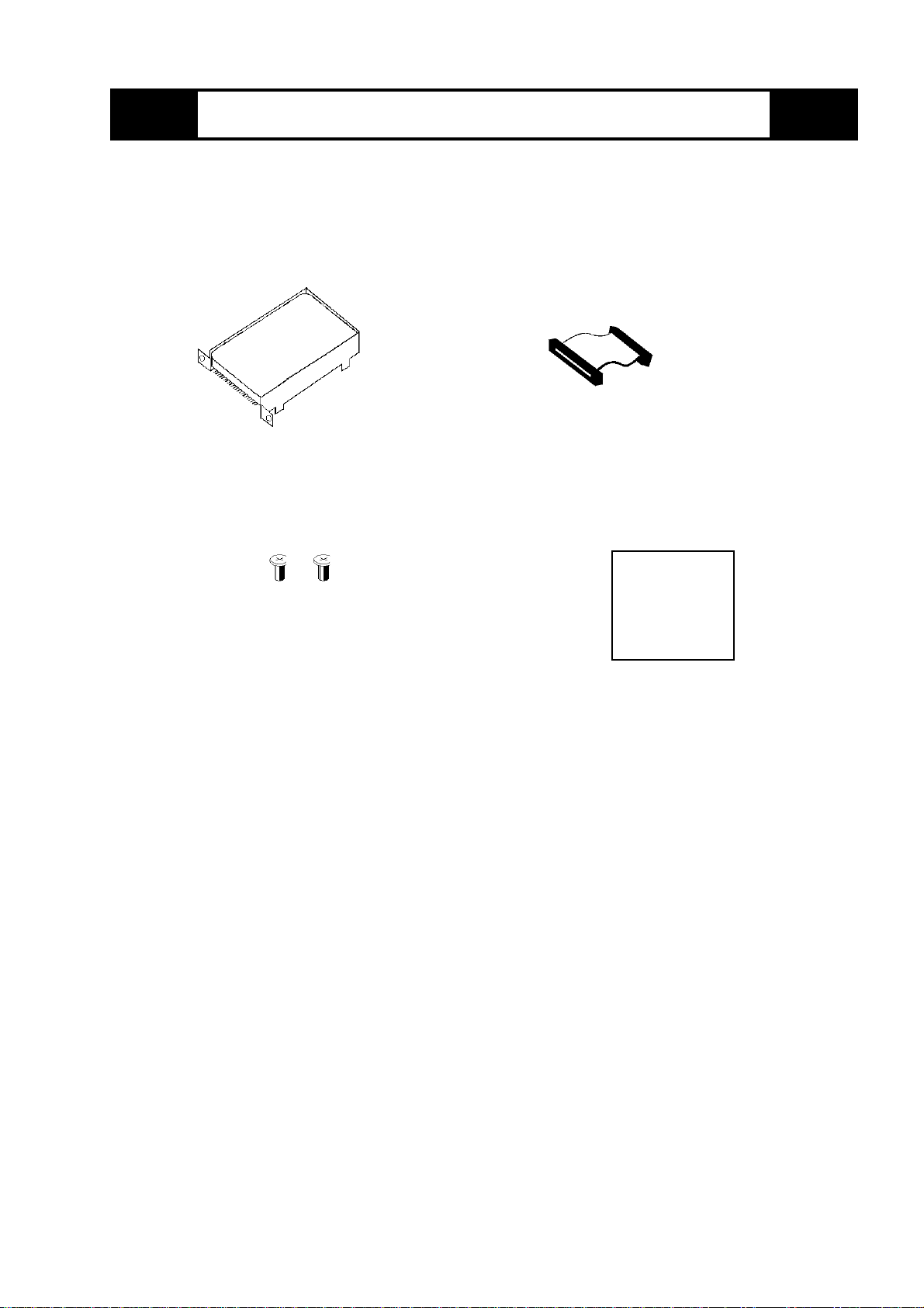
This flash file disk unit is made by the Digital Electronics Company for use with
its Panel Computer 5700Series devices.
(All product names that appear in this manual are the trademarks of
their respective companies)
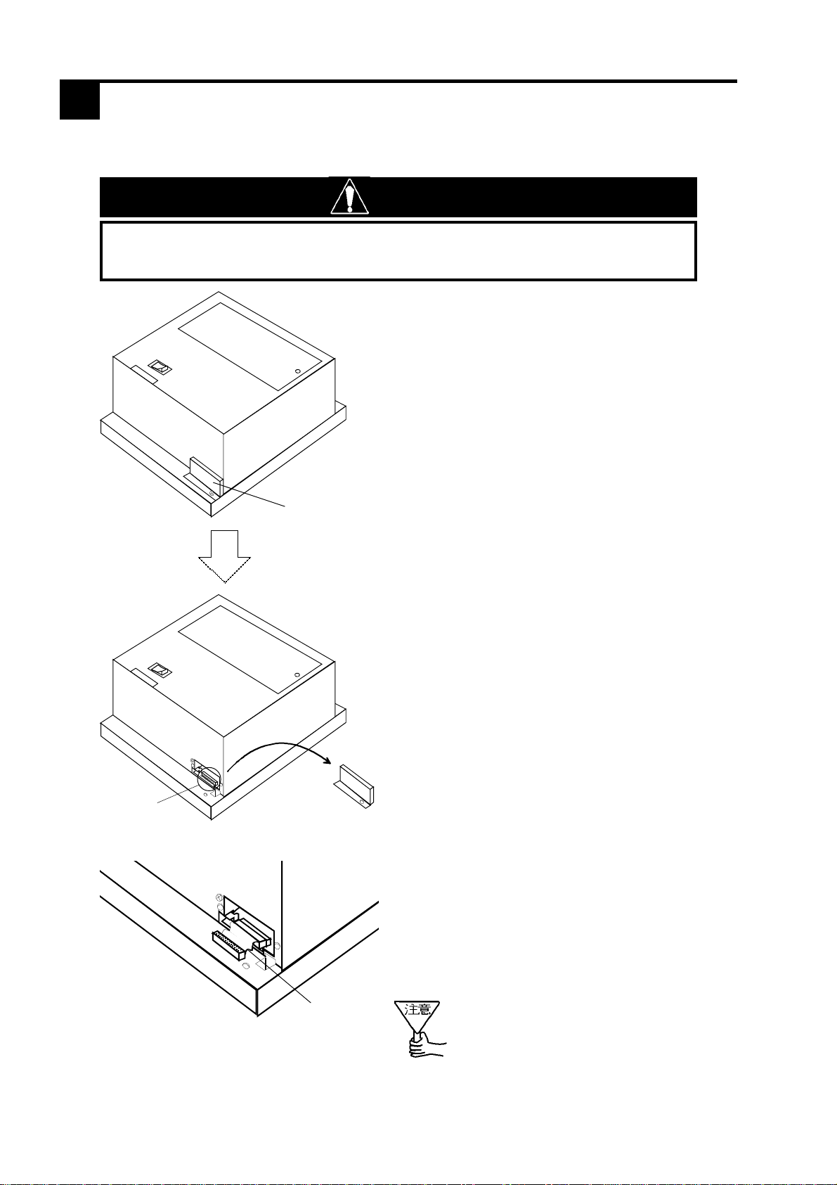
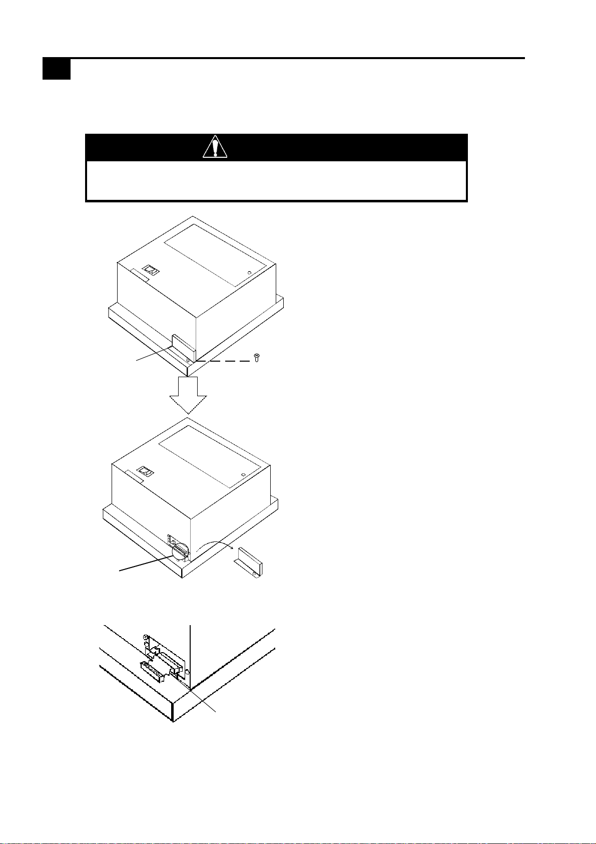
•Be sure not to jar or bump this unit when installing it in the Panel Computer.
Also, be sure to check that the Panel Computer’s power is disconnected be-
fore installing the unit, in order to prevent electrical shock.
•Do not attempt to modify or open the PL-FF020, due to the dangers of shock
and fire.
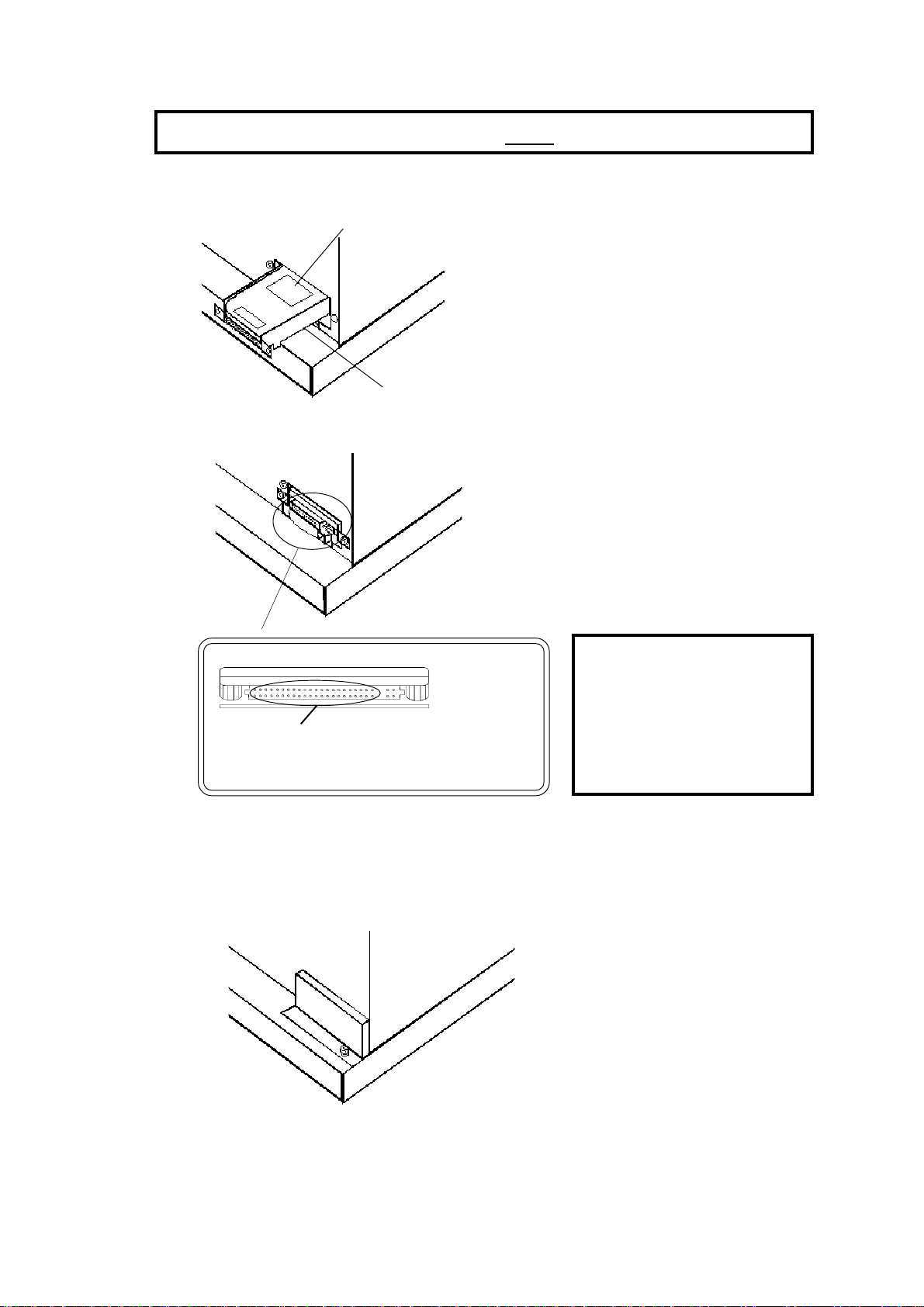
•When installing the PL-FF020, be sure to read the following “2. Installation”
section’s information completely to insure that the unit is correctly installed.
•The PL is not appropriate for use with aircraft control devices, aerospace
equipment, central trunk data trans-mission (communication) devices, nuclear
power control devices, or medical life support equipment, due to these devices
inherent requirements of extremely high levels of safety and reliability.
•When using the PL with transportation vehicles (trains, cars and ships), disas-
ter and crime prevention devices, various types of safety equipment, non-life
support re-lated medical devices, etc. redundant and/or failsafe sys-tem de
signs should be used to ensure the proper degree ofreliability and safety.
To Prevent Accidents
•Since the PL-FF020 is a precision instrument, be sure it is neither hit by nor
pressed strongly against another object. After unpacking, be sure the unit is not
dropped or jolted during installation. Also, any PL built in to a larger unit (i.e.
an operation panel) should be removed and packed separately prior to ship-
ping.
•Be sure water, liquids or metal particles are not allowed to enter the unit. Any of
these may cause either a breakdown or an electrical shock.
•After turning the unit OFF, wait 3 seconds before turning it ON again.
•Do not store or operate this unit near chemicals, or where there are chemical
fumes.
•Do not allow anyone other than Digital’s own service staff to perform mainte-
nance or adjustments to this unit.
•To prevent damage to file data, be sure to shut down the unit's OS before turn-
ing OFF the main power.
PL-FF020
Operation Instructions
Warning - Safety Precautions

‑2‑
■Connector Cable (1)
■PL-FF020 (1)
■Attachment Screws (2) ■Operation Instructions
(PL-FF020)
Operation
Instructions
Please check that the following items are all included in your package.
Digital has taken the utmost care to insure the quality of this
product when it was shipped, however, should, for any reason,
problems or damage have occurred during shipping, please
contact your Digital representative immediately for service.
Package Contents

‑3‑
■Features
■Environment
N a m e PL-FF020
Memory 20Mbytes
Sector Size 512 bytes
Logic Heads 4
Logical Cylinders 344
Logial Sectors 32
Electric Power 0.32W(TYP)
During Read/Write: 0.27W(TYP)/0.32W(TYP)
Interface ATA - 2 (IDE)
No. of Reads/Writes 250,000 per sector
MTBF 500,000 hours
Hardware Specifications
1
PL - FF020
Operating Temperature PL-5700T1,PL-5701T1:0 to 45 deg. C
PL-5700S1,PL-5701S1:0 to 40 deg. C
PL-5700L1,PL-5701L1:0 to 40 deg. C
Storage Temperature -10 to 60 deg. C
Ambient Humidity 30 to 85% (no condensation)
Noise Resistance Noise Voltage: 1500Vp-p
(Depends onNoise Simulator) Pulse Width:50ns, 500ms, 1us
Static Resistance 5kV
Vibration Resistance When moving - 10 to 25Hz
(X,Y, and Z dir.; each30 min. 19.6m/s2)
Shock Resistance (WhenStored) 29400m/s2(0.2ms)<Unit only>

‑4‑
Digital Electronics Corporation
559-0031
Osaka-shi, Suminoe-ku, Nanko-Higashi 8-2-52
Tel. (81-6) 6613 - 1101 (General no.)
FAX (81-6) 6613 - 5888
nConcerning the EPROM's Lifetime:
Normal flash EPROM chips have a limit to the number of
times they can write or delete data. As a result, data backups
should be performed regularly to ensure the safety and integrity
of the User's data.
nConcerning Error Rates
If the PL's OS detects an error in any of the Flash EPROM's
sectors, that sector is then labeled as bad and not written to
again.

‑5‑
Remove the HDD cover
HDD Connector
HDD
Cover This drawing is for the PL-5700
(3 slot) type
WARNING
Use the following steps to install the PL-FF020in the PL.
WARNING: Shock Danger! Be sure to unplug the PL unit prior to
installing the PL-FF020
1)
Remove the PL unit’s
hard disk drive cover’s
attachment screw.
Installation
2)Insert the PL-FF020unit’s
attachment cable into the HD
connector. Be sure the cable’s
red line is facing the direction
shown here.
Red Line
2

‑6‑
When the Heat Protector is NOT Needed
3) Attach the PL-FF020and
secure it in place with the
two screws given.
Be sure the side
with the seal is
facing up.
PL-FF020
4) Insert the cable into the PL -
FF00* unit’s connector. Be
careful that the pins are aligned
as shown in the drawing here.
(The four pins on the far right
will be unused)
5) Place the cover back in
place, and re-attach its
screws.
CAUTION:
If the pins are
insertedincorrectly,
the unit may be
damaged !
<PL-FF020Connector>
Connect cable here
NOTE: Attach a jumper plug to change from Master to Slave

‑7‑
PhoenixBIOSSetup‑Copyright1985‑95PhoenixTechnologiesLtd.
Main Advanced Power Exit
1) Turn the PL unit’s power ON.
2) When the “Press <F2> to enter SETUP”message
appears, press your PC’s F2 key.
The Setup utility will start and the following screen
will appear.
F1Help ↑↓SelectItem ‑/+ChangeValues F9SetupDefaults
ESCExit ←→SelectMenu EnterSelect Sub‑Menu F10PreviousValues
Operation Keys
Displays the keys used (enabled) during Setup, and their
function(s)
Help Information Display Area
Provides detailed information about the currently highlighted
(cursor position) item
System Settings Area
Displays the current System Settings for each Menu area
(Main, Advanced, Power, etc.)
Menu Bar
Shows the Setup program’s 4 menus. Use the cursor keys to
move to that area’s information.
SystemTime: [15:00:00]
SystemData: [08/25/1995]
DisketteA: [NotInstalled]
DisketteB: [NotInstalled]
IDEAdapter0Master (None)
IDEAdapter0Slave (None)
VideoSystem [EGA/VGA]
MemoryCache
MemoryShadow
Bootsequence: [C:thanA:]
SystemMemory: 640KB
ExtendedMemory: 7168KB
ItemSpecificHelp
<Tab>,<Shift‑Tab>,or
<Enter>selectsfield.
▲
Hardware Setup
3

‑8‑
The Setup Utility’s keys have the following functions:
[F1][F1]
[F1][F1]
[F1] Displays a detailed explanation of the Setup
area’s currently highlighted function. The
[↑][↓] arrow keys can then be used to scroll
through the information.
[[
[[
[↑↑
↑↑
↑][][
][][
][↓↓
↓↓
↓]]
]]
]Moves the cursor up or down; allows you to
select different menu items.
[‑][+][‑][+]
[‑][+][‑][+]
[‑][+] Used to change the value of the current item.
[F9] Returns System Display Items to their original
(default) setting(s).
[ESC] Displays the Exit menu.
[[
[[
[←←
←←
←][][
][][
][→→
→→
→]]
]]
]Changes (Moves between) menus
[Enter] When the cursor is on a menu item showing a
▲, pressing the [Enter] key will bring up a
sub-menu. Pressing the [ESC] key backs you
out to the main menu.
[F10] Pressing this displays the currently recorded
CMOS data for the selected item.
3) Placing the cursor on the “IDE Adaptor 0 Master”selection
and pressing the [Enter] key will bring up the following
screen.
ItemSpecificHelp
F1HelpF1Help
F1HelpF1Help
F1Help↑↓↑↓
↑↓↑↓
↑↓SelectItem‑/+ChangeValuesF9SetupDefaultsSelectItem‑/+ChangeValuesF9SetupDefaults
SelectItem‑/+ChangeValuesF9SetupDefaultsSelectItem‑/+ChangeValuesF9SetupDefaults
SelectItem‑/+ChangeValuesF9SetupDefaults
ESCExitESCExit
ESCExitESCExit
ESCExit←→←→
←→←→
←→SelectMenuEnterExecuteCommandF10PreviousValuesSelectMenuEnterExecuteCommandF10PreviousValues
SelectMenuEnterExecuteCommandF10PreviousValuesSelectMenuEnterExecuteCommandF10PreviousValues
SelectMenuEnterExecuteCommandF10PreviousValues
Attemptsto
automaticallydetect
thedrivetypefor
drivesthatcomply
withANSI
specifications.
AutotypeFixedDisk: [PressEnter]
Type: [None]
Cylinders:
Heads:
Sectors/Track:
WritePrecomp:
IDEAdapter0Slave(None)
PhoenixBIOSSetup‑Copyright1985‑95PhoenixTechnologiesLtd.
Main Advanced Power Exit

‑9‑
PhoenixBIOSSetup‑Copyright1985‑95PhoenixTechnologiesLtd.
Main Advanced Power Exit
4)Placing the cursor on top of the “Autotype Fixed Disk”
selection and pressing the [Enter] key will automatically
register the current hard disk’s type.
5) Pressing the [ESC] key will automatically display the Exit
Menu’s screen.
SaveChanges&Exit
DiscardChanges&Exit
GetDefaultValues
LoadPreviousValues
SaveChanges
ItemSpecificHelp
Exitafterwritingall
changedSETUPitem
valuestoCMOS.
F1Help ↑↓SelectItem ‑/+ChangeValues F9SetupDefaults
ESCExit ←→SelectMenu EnterExecuteCommand F10PreviousValues
6) To exit the Setup program, place the cursor on top of
the “Save Changes and Exit”selection and press the [Enter]
key.
Software Setup
4
After completing the hardware setup, in order to record
all data and application(s) use your OS (MS-DOS or
Windows) to create partitions and initialize the hard disk.
Please consult your OS’s operation manuals for details.
© Copyright 1998 Digital Electronics Corporation.
Note
Be aware that the Digital Electronics Corporation shall not be held liable for any real or
estimated damages or losses, or third party claims resulting from the use of this product.
Table of contents
Other Digital Electronics Corporation Industrial PC manuals

Digital Electronics Corporation
Digital Electronics Corporation PL-3600T Series User manual

Digital Electronics Corporation
Digital Electronics Corporation PL-3900T Series User manual

Digital Electronics Corporation
Digital Electronics Corporation PL-3700T Series User manual

Digital Electronics Corporation
Digital Electronics Corporation PS-2000B Series User manual