Digital Electronics Corporation PL-3900T Series User manual

1
PL-3900T Series
Installation Guide
Package Contents
(1) PL Unit (1)
(2) Installation Guide (1) <This Guide>
(3) Warning/Caution Information (1)
(4) Installation Gasket (Attached to the front
module) (1)
(5) Installation Fasteners (4 fasteners per
set) (3 set)
(6) USB Cable Clamp (2 ports) (2)
(7) USB Holder (fasteners: 1, screws: 2) (1 set)
(8) Power Connector (For AC type or DC
type) (1)
• Be careful when installing the PL notto
damage the built-in HDD.
This unit has been carefully packed, with
special attention to quality. However, should
you find anything damaged or missing,
please contact your local PL distributor
immediately.
When you order a PL unit built to your
specifications, that PL package should
include each optional item’s Installation
Guide. Please use that guide to check the
contents of each optional item’s package.
About the Manual
For the detailed information on PL series,
refer to the following manuals.
• PL3000 Series Hardware Manual
• PL3000 Series Reference Manual
•PL3000 Series API Reference Manual
Manual can be downloaded from Pro-face
Home Page.
URL
http://www.pro-face.com/otasuke/
• The drivers and utilities for PL can be
downloaded from Pro-face Home Page.
Caution
Be sure to read the “Warning/Caution
Information” on the attached sheet before
using the product.
For AC type For DC type

2
Part Names and Functions
Name Description
APower LED /
RAS status lamp (POWER)
B Disk access lamp (DISK)
CFrontcover —
DHardware reset switch
(RESET) Resets the PL unit and returns the system from Soft
OFF.*1
*1 The Soft OFF refers to the state when Windows®has been shut down and the power is provided
only for the electric circuit to boot system. This Soft OFF State is different from Windows®System
Standby.
EUSBinterface
1 port. USB2.0 compatible. Type-A connector is used.
Front AB
CDE
LED Indicates
Green (lit) Normal operation (power is on)
Green (blinking) Soft OFF state
Orange (lit) System monitor error (RAS error)
/ Touch Panel Self Test Error
Orange/Red
(blinking) Backlight burnout is detected.
Not lit Power is OFF
LED Indicates
Green (lit) When HDD or IDE is accessed
Not lit When neither HDD nor IDE is
accessed
Power supply voltage DC5V±5%
Output current 500mA (Max.)
Maximum
communication distance 5m
3
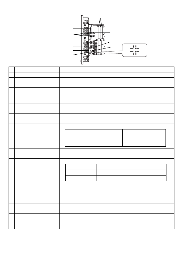
Name Description
F DVI-I interface (DVI-I) For analog RGB output only.*1
*1 DVI monitor cannot be connected.
GEthernet interface
(LAN1) 10BASE-T/100BASE-TX/1000BASE-T Auto Changeover. This
interface uses an RJ-45 type modular jack connector (8 pins).
HEthernet interface
(LAN2) 10BASE-T/100BASE-TX Auto Changeover. This interface uses
an RJ-45 type modular jack connector (8 pins).
I Expansion slot For expansion board (PCI). 2 slots or 4 slots.
J Expansion slot cover Expansion slot cover is removed when mounting expansion
board and DIM module.
K HDD slot For serial ATA HDD unit. HDD slot 0 and then HDD slot 1
from the left.
LUSB interface
(USB1/2/3/4)
4 ports. USB2.0 compatible. Type-A connector is used.
MSpeaker output
interface (SPK) Mini pin jack connector
NHDD status lamp
(HDD0/HDD1)
For HDD0 and for HDD1 from left to right.
OSerial interface
(COM1) D-Sub 9-pin plug type. RS-232C, RS-422, RS-485
Changeover. CI (RI)/+5V Changeover.
PSerial interface
(COM2) D-Sub 9-pin plug type. RS-232C. CI (RI)/+5V Changeover.
QSerial interface
(COM3/COM4) D-Sub 9-pin plug type. RS-232C. COM3 and then COM4
from the top.
R RAS interface (RAS) D-Sub 9 pin socket type.
SCFcardinterface IDE-type connection *2
CF card (Type I/II) is available.
*2 Since an IDE-type connection is used, the unit is not hot-swappable. When inserting/removing the
CF card, be sure that power is turned OFF.
Right side
(2 slot type)
F
IJ
L
M
O
P
S
R
N
BN
A
K
Q
H
G
D
Power supply voltage DC5V±5%
Output current 500mA (Max.)
Maximum communication distance
5m
LED Indicates
Green (lit) HDD mounted (Normal operation)
Not lit No HDD mounted
4
• When attaching peripheral units to the PL, be sure the PL’s power cord is
disconnected from the main power supply.
General Specifications
Electrical Specifications
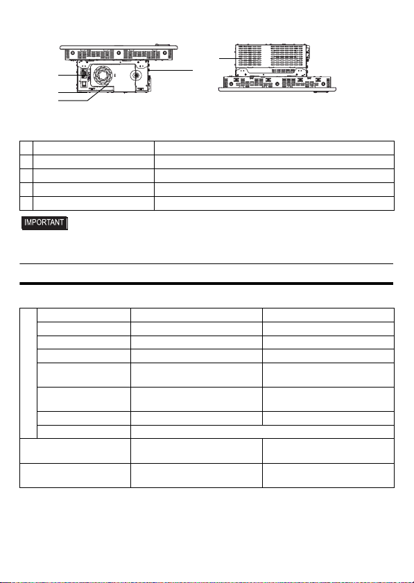
Name Description
T Fan cover System fan inside
U System fan A fan for cooling the PL unit.
V Power connector —
W Power switch AC type only.
Power Supply
DC type AC type
Input Voltage DC24V AC100 to 240V
Rated Voltage DC19.2 to 28.8V AC85 to 264V
Rated Frequency — 50/60Hz
Allowable Frequency
Range — 47 to 63Hz
Allowable Voltage
Drop 5ms or less 1 cycle or less (Voltage drop
interval must be 1s or more.)*1
Power Consumption 145W or less 145VA or less
In-Rush Current 40A or less
Voltage Endurance AC1000V 10mA for 1 minute
(
between charging and FG terminals
)AC1500V 20mA for 1 minute
(
between charging and FG terminals
)
Insulation Resistance DC500V 10MΩ(min.)
(
between charging and FG terminals
)DC500V 10MΩ(min.)
(
between charging and FG terminals
)
Bottom
(2 slot type)
T
V
Top
(2 slot type)
W
U
J
5
Environmental Specifications
• When using any of the PL’s optional devices, be sure to check that device’s specifica-
tions for any special conditions or cautions that may apply to its use.
• Be aware that not only does the Hard Disk have a fixed lifetime, but that accidents
can always occur. Therefore, be sure to back up your Hard Disk’s data regularly, or
prepare another Hard Disk unit that can be used for backup.
• The Hard Disk lifetime given here may be reduced due to unforeseen environmental
factors, however, generally speaking, the disk should last for 20,000 hours (of opera-
tion) or approximately 5 years, whichever comes first at an operating temperature of
20°C and 333 hours of operation per month. (HDD access frequency of 20% or less)
• Using the Hard Disk in an environment that is excessively hot and/or humid will
shorten the disk’s usage lifetime. A wet bulb temperature of 29°C or less is recom-
mended. This is equivalent to the following data.
• In order to extend the lifetime of the hard disk, Pro-face recommends you set the
Windows®2000’s [Control panel]-[Power Management option]-[Turn off hard disks]
selection or the Windows®XP’s [Control panel]-[Performance and Maintenance]-
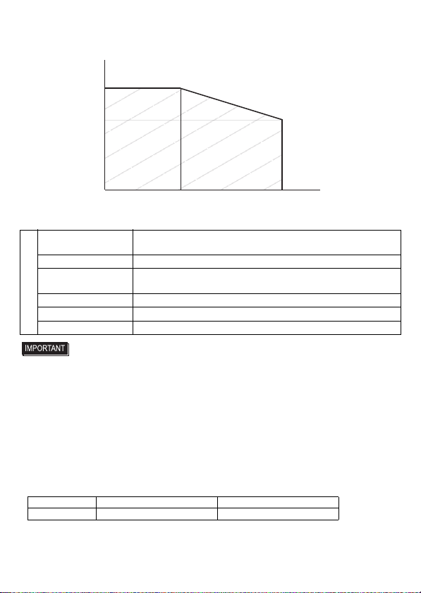
*1 When the total of the expansion slot power and theexternal load power exceeds 15W, the length of
the allowable voltage drop will be 20ms or less. For details, refer to the chart below.
Physical
Surrounding Air
Temperature 0 to 50°C :without HDD
5 to 50°C :with HDD
Storage Temperature -20 to +60°C
Ambient Humidity 10 to 90% RH (Not condensing, wet bulb temperature: 39°C or
less. Wet bulb temperature with HDD: 29°C or less.)
Storage Humidity 10 to 90% RH (Not condensing, wet bulb temperature:39°C or less.)
Dust Free of dust
Pollution Degree For use in Pollution Degree 2 environment
Temperature at 35°C at 40°C
Humidity no higher than 64% RH no higher than 44% RH
(ms)
20
14
035 40 (W)
15
Allowable Range
6
[Power Management option]-[Turn off hard disks] selection to turn the hard disk off
when the unit is not being operated. A setting of 5 minutes is recommended.
• Do not vibrate the hard disk continuously at the same frequency. Doing so may cause
the hard disk to reduce transfer speeds or stop temporarily.
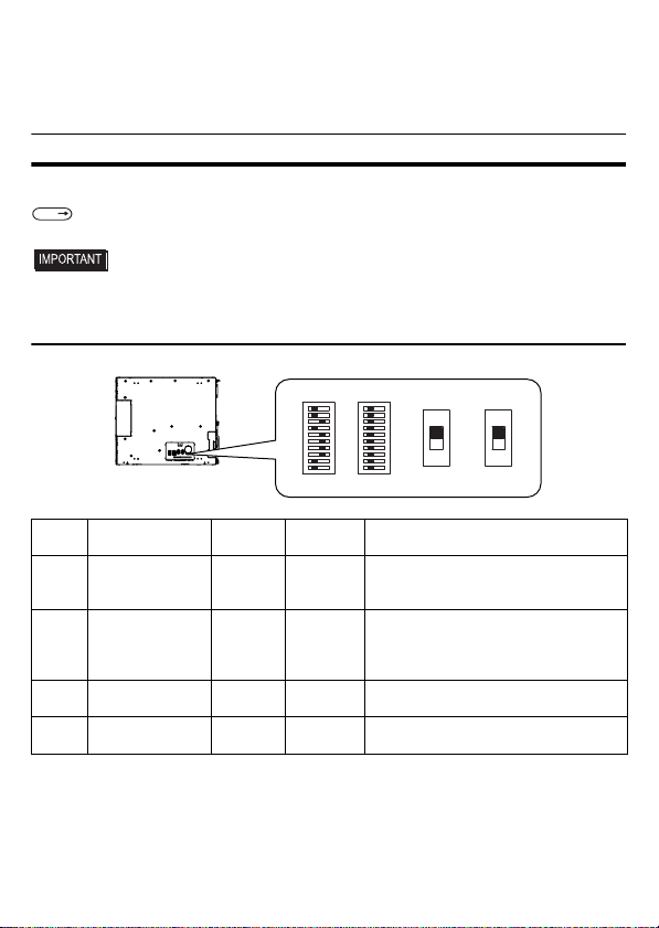
Internal Switches
To operate the internal switches, uninstall the control box and the front module.
• Make sure to turn off the power supply before using the switches. Adjusting the
switches while power is supplied may cause errors.
1. Internal switches of the control box
SEE
Installation/uninstallation of the front module and the control box (page 13)
Switch
Location
Switch Name
Compatible
I/F
Factory
Settings Description
SW1 System Set SW – See
System
Set Switch
10-point dip switch. For System Set
SW and the factory settings details,
see System Set Switch.
SW2 Serial Mode
Select SW COM1
All OFF
(RS-232C)
10-point dip switch. Designates COM1
communication settings. For Serial
Mode Select SW details, see Serial
Mode Select Switch.
SW3 CI(RI)/+5V
Changeover SW COM2 CI(RI) Changes # 9 pin (CI(RI) <---> +5V).
SW4 CI(RI)/+5V
Changeover SW COM1 CI(RI) Changes # 9 pin (CI(RI) <---> +5V).
1 10
1 10
SW4SW1 SW2 SW3
OFF
ON
ON
OFF
Bottom face of the control box
(CI)RI
5V

7
System Set Switch
Serial Mode Select Switch
Switch
No.
Description ON OFF
Factory
Settings
Notes
1 Internal setting.
Reserved Reserved
OFF Do not change. (Factory
setting)
2
Implements the
logical inversion
operation for RAS
output.
Normal
Close Normal
Open OFF
RAS output is a CLOSE state when
the SW and the system is ON. When
the SW is OFF, it is the opposite. The
RAS Output keeps Normal OPEN
when the Soft OFF state occurs or the
power turns OFF.
3
Sets up an enabled/
disabled state for the
front USB port execution
control function.
*1
*1 The Setting up an enabled/Disabled state for USB port execution control function is available for
only Windows®2000 and Windows®XP. Make sure to disable the function of the setting when
other OS is used.
Enabled Disabled ON
The front USB port is available
when the SW is ON. It is
unavailable when the SW is OFF.
4Internal setting.
Reserved Reserved
OFF Do not change. (Factory
setting)
5 to 8 ON
9 to 10
OFF
Switch
No.
Description ON OFF
RS-232C RS-422 RS-485
1
Internal setting.
Reserved Reserved OFF*1 OFF*1 OFF*1
2
Changes COM1’s
communication
method RS-422/RS-485 RS-232C
OFF ON ON
3
Changes COM1’s
communication
method RS-422/RS-485 RS-232C
OFF ON ON
4
Changes SD (TXD)
data’s output mode
SD (TXD) data
output is
controlled via the
RS (RTS) signal.
SD (TXD) data
output is NOT
controlledviathe
RS(RTS)signal.
(normally output)
OFF ON/
OFF ON/
OFF*2
5
Switches the SD
(TXD) termination
resistance ON/OFF
Inserts
termination
resistance of
220
Ω
between
SDA and SDB.
No termination
OFF ON ON/
OFF*3
8
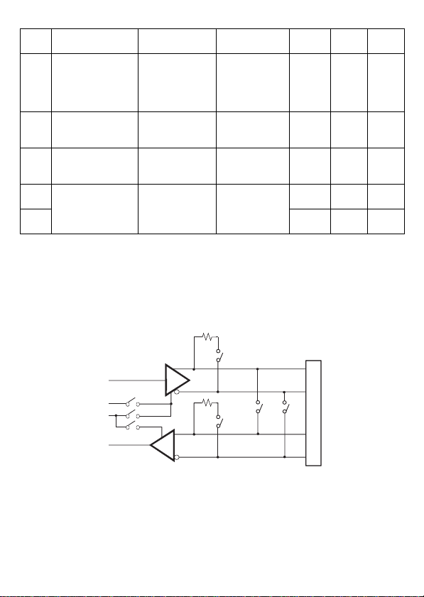
Serial Mode Select Switches (SW4 to SW10) operate as shown in the circuit diagram below.
6
Switches the RD
(RXD) termination
resistance ON/OFF
Inserts
termination
resistance of
220
Ω
between
RDA and RDB.
No termination
OFF ON ON/
OFF*3
7
Switches the
shorting of SDA and
RDA ON or OFF
Shorts SDA and
RDA
(RS-485 mode)
No shorting
(RS-422 mode)
OFF OFF ON
8
Switches the
shorting of SDB and
RDB ON or OFF
Shorts SDB and
RDB
(RS-485 mode)
No shorting
(RS-422 mode)
OFF OFF ON
9
RS(RTS)Automatic
control mode
(enabled only when
RS-485 mode)
The data is
automatically
controlled via the
RS (RTS) signal.
The data is not
automatically
controlledviathe
RS (RTS) signal.
OFF OFF ON/
OFF*2
10 OFF OFF ON/
OFF*2
*1 Be sure to keep the settings, “OFF”.
*2 Set switches number 9 and 10 to ON when the SD (TXD) output driver is automatically controlled
with RS (RTS). Set switch number 4 to OFF.
Set switches number 9 and 10 to OFF when the SD (TXD) output driver is controlled with the RS
(RTS) signal. Set switch number 4 to ON.
*3 If you use the termination resistance, base your settings on the connection specifications.
Switch
No.
Description ON OFF
RS-232C RS-422 RS-485
SW4
SW9
SW10
SW5
SW7
SW6
SW8
RT(RTS) Automatic
control
COM1
SD(TXD)
RT(RTS)
SDA
SDB
RDA
RDB
9
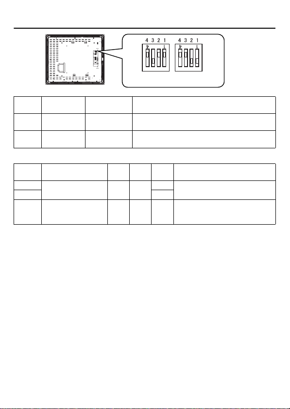
2. Internal switches of the front module
Touch Panel Set SW
Switch
Location
Switch Name Factory
Settings Description
SW1 Touch Panel
Set SW 1:ON, 2:ON,
3:OFF, 4:OFF 4-point dipswitch. For Touch Panel Set SW
details, see “Touch Panel Set SW”.
SW2 — 1:OFF, 2:OFF,
3:ON, 4:OFF Internal setting.
Do not change. (Factory setting)
SW1
SW2 ON
ON
Rear face of the front module
Switch
No. Description ON OFF
Factory
Settings
Notes
1 to 2 Internal setting
Reserved Reserved
ON Do not change. (Factory setting)
3OFF
4Cancellation function
of two point touch on
the touch panel*1
Enabled Disabled
OFF
The middle point is not considered to be
touched when the SW is ON. It is considered
to be touched when the SW is OFF.
*1 When two points are pushed, it is considered that middle point between the two points is touched
according to the nature of the analog resistive touch panel. When the switch, etc. is set on the middle
point,itwillbeenabledandmayoperate.Topreventsuchaswitchfrommalfunctionincaseofpushing
two points, turn ON the SW No.4 in advance, then the middle point will be disabled for two point touch.
10
External Interfaces
• This PL unit’s serial port is not isolated.
When the host (PLC) unit is also not
isolated, and to reduce the risk of dam-
aging the RS-232C/RS-422/RS-485
circuit, be sure to connect pin #5 SG
(Signal Ground) terminal.
• Never connect NC to COM1.
• Connect FG to shell.
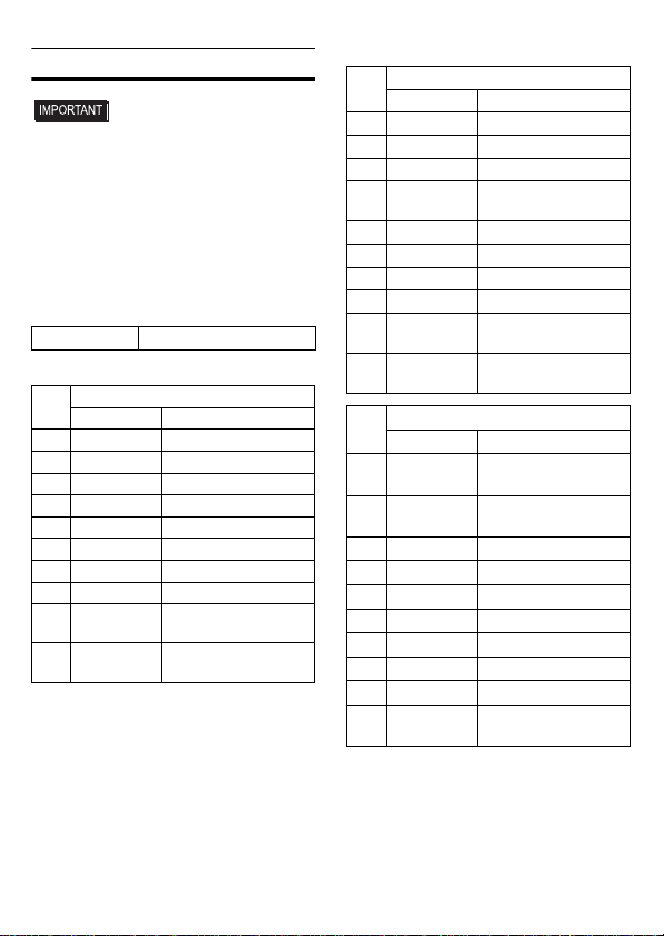
Serial Interface
(COM1, COM2, COM3, COM4)
COM1, COM2, COM3, COM4
COM1
*3 To change the communication method, set
the dip switch located on the circuit board in
the PL unit to the desired position.
For details, see [Internal Switches].
Interfit Bracket #4-40 UNC
Pin #
RS-232C
Signal Name
Meaning
1 CD Carrier Detect
2 RD(RXD) Receive Data
3 SD(TXD) Send Data
4 ER(DTR) Data Terminal Ready
5 SG Signal Ground
6 DR(DSR) Data Set Ready
7 RS(RTS) Request to Send
8 CS(CTS) Clear to Send
9CI(RI)/+5VCalled status display/
+5V Output 0.5A*1 *2
*1 Only COM1 and COM2 are available for
switchingto+5V.COM3andCOM4areused
exclusively for CI (RI).
*2 Slideswitchon the circuitboardin the PLunit
switches between CI (RI) and +5 V. For
details, see [Internal Switches].
Shell
FG Frame Ground
(Common with SG)
Pin #
RS-422 *3
Signal Name
Meaning
1 RDA Receive Data A(+)
2 RDB Receive Data B(-)
3 SDA Send Data A(+)
4ERA Data Terminal Ready
A(+)
5 SG Signal Ground
6 CSB Clear to Send B(-)
7 SDB Send Data B(-)
8 CSA Clear to Send A(+)
9ERB Data Terminal Ready
B(-)
Shell
FG Frame Ground
(Common with SG)
Pin #
RS-485*3
Signal Name
Meaning
1DATA+ Send/Receive Data
(+)
2DATA- Send/Receive Data
(-)
3 NC No Connection
4 NC No Connection
5 SG Signal Ground
6 NC No Connection
7 NC No Connection
8 NC No Connection
9 NC No Connection
Shell
FG Frame Ground
(Common with SG)
11
RAS Interface
• Be sure to use only the rated voltage
level when using pin #1 (+12V) for
external power output. Failure to do so
can lead to a unit malfunction or acci-
dent.
• For the circuit diagram, refer to “PL3000
Series Reference Manual”.
Installations
• Before installing the PL unit on the
panel, detach the control box from the
front module to configure the settings
of the internal switches.
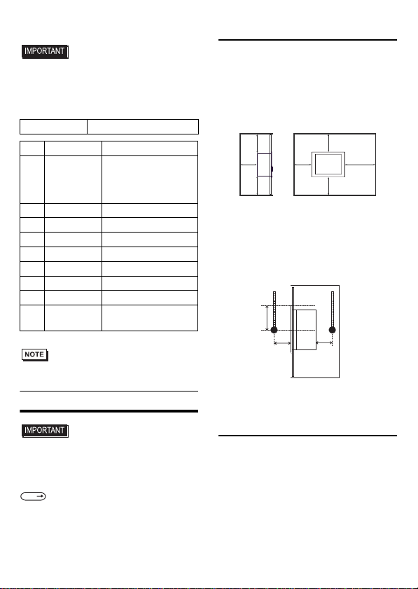
1. Installation Requirements
• For easier maintenance, operation, and
improved ventilation, be sure to install the
PL at least 50mm [1.97 in.] away from
adjacent structures and other equipment.
For the face to which the cable is con-
nected, however, a space of 120 mm [4.72
in.] or more is necessary for cable curve.
• Be sure that the surrounding air temperature
and the ambient humidity are within their
specified ranges.
When installing the PL on the panel of a
cabinet or enclosure, “Surrounding air tem-
perature” indicates both the panel face and
cabinet or enclosure’s internal temperature.
• Be sure that heat from surrounding equip-
ment does not cause the PL to exceed its
standard operating temperature.
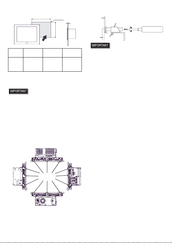
2. PL Installation
(1) Create a Panel Cut following the dimen-
sions in the following table. Also, deter-
mine the panel thickness according to the
panel thickness range with due consider-
ation of panel strength.
Interfit Bracket #4-40 UNC
Pin #
Signal Name
Meaning
1 +12V
Output Current:
100mA or less
Output Voltage:
12V
±
5%
2 DOUT0(+) Data out 0(+)
3 DOUT1(+) Data out 1(+)
4 DIN0(+) Data in 0(+)
5 DIN1(+) Data in 1(+)*1
*1 Can be used as reset input.
6 GND Ground
7 DOUT0(-) Data out 0(-)
8 DOUT1(-) Data out 1(-)
9DINCOM Data in ground
common
SEE
Installation/uninstallation of the
front module and the control
box, Internal Switches
Unit:mm[in.]
120
[4.72]
50
[1.97]
50
[1.97]
50
[1.97]
50
[1.97]
50
[1.97]
50
[1.97]
Panel face Cabinet
interior
30
[1.18] 30
[1.18]
unit:mm[in.]
50
[1.97]
12
(2) Confirm that the installation gasket is
attached to the PL unit and then place the
PL unit into the panel from the front.
• It is strongly recommended that you
use the installation gasket, since it
absorbs vibration in addition to repel-
ling water.
For the procedure for attaching the
installation gasket, refer to “PL3000
Series Hardware Manual”.
(3) Insert each fastener’s hook into the slot
and tighten it with a screwdriver. Tighten
the 12 screws gradually in an even, criss-
cross pattern.
• Tightening the screws with too much
force can damage the PL unit.
• The torque required to tighten these
screws is 0.8 N•m.
PL X Y
Panel
thickness
PL-3900T
Series
419.5
[16.52 ]
352.5
[13.88 ]
1.6[0.06] to
10.0[0.39]
PL
X
Unit:mm[in.]
Y
Under
4-R3[0.12] Panel
thickness
+1
-
0
+
0.04
-
0
+1
-
0
+
0.04
-
0
Insertion
Slots
Panel
Hook
PL
Installation Fastener
Tighten against
the board.

13
Installation/uninstallation of the
front module and the control box
• To avoid an electric shock, prior to instal-
lation/uninstallation of the front module
and the control box, confirm that the PL
unit’s power supply is completely turned
OFF, via a breaker, or similar unit.
1. Uninstalling the front module and
the control box
(1) Unscrew the three attachment screws to
detach the cover for the flexible cable.
(2) Disconnect the flexible cable.
(3) Remove four screws on the installation
fasteners for the control box.
(4) Slide the control box in direction shown
by the arrow.
(5) Lift the control box and remove the front
module tabs from the slot on the installa-
tion fasteners for the control box. Then
remove the control box.
2. Installing the front module and the
control box
Install the control box to the front module
in the reverse order of the uninstallation
steps. The necessary torque is 0.5N•m to
0.6N•m in every step.
Flexible Cable
Cover
Flexible Cable
Use the bridge
position as a guide.

14
Wiring
• To avoid an electric shock, prior to con-
necting the PL unit’s power cord terminals
to the power terminal block, confirm that
the PL unit’s power supply is completely
turned OFF, via a breaker, or similar unit.
• Any other power level can damage
both the PL and the power supply.
• Since DC type has no power ON/OFF
switch, be sure to attach a breaker-
type switch to its power cord.
• When the FG terminal is connected, be
sure the wire is grounded.
1. Wiring the AC type power supply cable
• When the FG terminal is connected, be
sure the wire is grounded. Not
grounding the PL unit will result in
excessive noise. Use your country’s
applicable standard for grounding.
Power Cord Specifications
Use copper conductors only.
Wiring
When connecting the power code, use the
following items when performing wiring.
(Items are made by Phoenix Contact.)
• Accompanying power supply connector is
a CA7-ACCNL-01 of Pro-face or FKC2,5/
3-STF-5,08 of Phoenix Contact.
Connecting the Power Cord
(1) Confirm that the power is not supplied to
the PL unit.
(2) Push the Opening button by a small and flat
screw driver to open the desired pin hole.
(3) Insert each pin terminal into its each
hole. Release the Opening button to
clamp the pin place.
(4) After inserting all three pins, insert the
Power Plug into the Power Connector at
PL. Fix the plug with two minus screws.
• Confirm that all wires are connected
correctly.
• The torque required to tighten these
screws is 0.5 to 0.6 N•m [5-7Lb•In].
• To prevent the possibility of a terminal
short, use a pin terminal that has an
insulating sleeve.
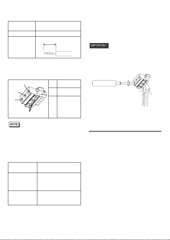
2. Wiring the DC type power supply cable
• When the FG terminal is connected, be
sure the wire is grounded. Not ground-
ing the PL unit will result in excessive
noise. Use your country’s applicable
standard for grounding.
Power Cord
Diameter 0.75 to 2.5mm2
(18 - 12 AWG)
Conductor Type
Simple or Stranded Wire*1
*1 IftheConductor’send(individual)wiresarenot
twistedcorrectly,theendwiresmayeithershort
against each other, or against an electrode.
Conductor
Length
Recommended
Driver SZS 0.6x3.5 (1205053)
10mm [0.39in]
Recommended
Pin Terminals
AI 0.75-10GY(3201288)
AI 1-10RD (3200182)
AI 1.5-10BK (3200195)
AI 2.5-12BU (3200962)
Recommended
Pin Terminal
Crimp Tool CRIMPFOX ZA3
(1201882)
L
N
FG
Opening button
Black
White
Green/Yellow
AC power supply cable
15
Power Cord Specifications
Use copper conductors only.
Power Connector (Plug) Specifications
• Accompanying power supply connector is
CA5-DCCNL-01 of Pro-face or
GMVSTBW2.5-3-STF-7.62 of Phoenix
Contact.
When connecting the power code, use the
following items when performing wiring.
(Items are made by Phoenix Contact.)
Connecting the PL Power Cord
(1) Confirm that the power is not supplied to
the PL unit.
(2) Loosen three screws in the center of the
Power Connector (plug).
(3) Strip the power cord, twist the conductor’s
wire ends, insert them into the pin terminal
and crimp the terminal. Attach the terminal
to the Power Connector.
• Use a flat-blade screwdriver (Size 0.6 x
3.5) to tighten the terminal screws.
The torque required to tighten these
screws is 0.5 to 0.6 N•m [5-7Lb•In.].
• Do not solder the cable connection.
(4) Attach the Power Connector (plug) to the
PL and fix it to the PL main unit with
right/left tightening screws.
3. Power Supply Cautions
• Input and Output signal lines must be sepa-
rated from the power control cables for
operational circuits.
• To improve the noise resistance, be sure to
twist the ends of the power cord wires
before connecting them to the Power con-
nector (Plug).
• The PL unit’s power supply cord should
not be bundled with or kept close to main
circuit lines (high voltage, high current), or
input/output signal lines.
• To reduce noise, make the power cord as
short as possible.
• If the supplied voltage exceeds the PL
unit’s range, connect a voltage transformer.
• Between the line and the ground, be sure to
use a low noise power supply. If there is an
excess amount of noise, connect a noise
reducing transformer.
Power Cord
Diameter 0.75 to 2.5mm2
(18 - 12 AWG)
Conductor Type
Simple or Stranded Wire
*1
*1 If the Conductor’s end (individual) wires are not
twistedcorrectly,theendwiresmayeithershort
against each other, or against an electrode.
Conductor
Length
+ 24V
-
0V
FG
Grounding
Terminal
connected
to the PL
chassis
Recommended
Driver SZF 1-0.6x3.5
(1204517)
Recommended
Pin Terminals
AI 0.75-8GY (3200519)
AI 1-8RD (3200030)
AI 1.5-8BK (3200043)
AI 2.5-8BU (3200522)
Recommended
Pin Terminal
Crimp Tool CRIMPFOX ZA 3
(1201882)
7mm
[0.28in]
+
Insertion Direction
−
FG
FG
+
-
16
• The temperature rating of field installed
conductors: 75°C only.
• Use voltage and noise reducing trans-
formers with capacities exceeding
Power Consumption value.
• Branch Circuit Protective device shall be
use for rating 20A for DC24V input device.
• Connect a surge absorber to handle
power surges.
• Be sure to ground the surge absorber
(E1) separately from the PL unit (E2).
Select a surge absorber that has a maxi-
mum circuit voltage greater than that of
the peak voltage of the power supply.
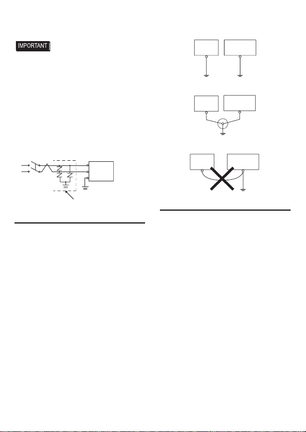
4. Grounding Cautions
• Be sure to create an exclusive ground for the
Power Cord’s FG terminal. Use a grounding
resistance of 100Ω, a wire of 2mm2or thicker,
or your country’s applicable standard.
• The SG (signal ground) and FG (frame
ground) terminals are connected internally
in the PL unit.
When connecting the SG line to another
device, be sure that the design of the system/
connection does not produce a shorting loop.
• The grounding wire should have a cross
sectional area greater than 2mm2. Create
the connection point as close to the PL unit
as possible, and make the wire as short as
possible. When using a long grounding
wire, replace the thin wire with a thicker
wire, and place it in a duct.
5. Input/Output Signal Line Cautions
• All PL Input and Output signal lines must
be separated from all operating circuit
(power) cables.
• If this is not possible, use a shielded cable
and ground the shield.
• To improve noise immunity, it is recommended
to attach a ferrite core to the power cord.
Lightening Surge Absorber
E1 E2
FG
PL
Other
Equipment
Exclusive Grounding
(BEST)
PL unit
Other
Equipment
Common Grounding (OK)
PL unit
Other
Equipment
Common Grounding
(Not OK)
PL unit
17
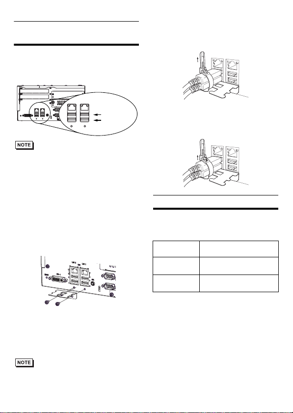
To prevent the USB cable
from coming off
Attaching the USB Cable Clamp
(1) Place the PL unit face-down on a flat sur-
face as shown below. Your PL unit has
four USB connectors.
• When using two or more USB ports, be sure
to first connect one USB cable to the lower
USB connector, and then connect the sec-
ond USB cable to the upper USB connector.
• When using only one of the USB ports, be
sure to use the lower USB connector. This
allows you to securely clamp the USB
cable in the cable clamp.
• The USB cable clamp is not compatible
with the USB connector on the front face.
(2) Fix the USB holder with two screws.
The torque required to tighten these
screws is 0.5 to 0.6 N•m.
(3) As the figure shows, pass the USB Cable
Clamp’s band around the depressed sur-
face of the holder, twist the USB Cable
Clamp’s band around the USB cable, pull
the band in the direction of the arrow,and
then fasten the band using the clamp.
• Be sure the clamp is securely holding the
USB cable’s plug and collar.
• Be sure the clamp is positioned as shown
below, with the clamp pointing upwards - not to
the side. This is to keep the clamp from interfer-
ing with nearby connectors and their cables.
Removing the USB Cable Clamp
(1) To remove the clamp from the USB cables,
push down on the clamp strap’s clip to
release it while pulling up on the clamp.
UL/c-UL Approval
The following units are UL/c-UL listed
products:
(UL File No.E220851)
These products conform to the following
standards:
UL508
Industrial Control Equipment
CSA-C22.2 No.142-M1987
(c-UL Approval)
Process Control Equipment
<Cautions>
Be aware of the following items when
building the PL into an end-use product:
1
24
3
USB
LAN1 LAN2
1
24
3
USB
LAN1 LAN2
SPK
DV1-I
RESET
LowerUSB
Interface
UpperUSB
Interface
Product
Model No.
UL/c-UL
Registration Model No.
APL3900-TA 3582302-0
Front Module:3620003-03
APL3900-TD 3582302-11
Front Module:3620003-03
18
• The PL unit’s rear face is not approved as
an enclosure. When building the PL unit
into an end-use product, be sure to use an
enclosure that satisfies standards as the
end-use product’s overall enclosure.
• The PL unit must be used indoors only.
• Install and operate the PL with its front
panel facing outwards.
• If the PL is mounted so as to cool itself
naturally, be sure to install it in a vertical
panel. Also, according to the installation
requirements, create space around the rear
face of the PL unit. The temperature must
be checked on the final product in which
the PL unit is installed.
• For use on a flat surface of a Type 1 Enclo-
sure.
CE Marking
• APL3900-TA unit is CE marked product
that conforms to EMC directives and Low
Voltage Directives EN55011 Class A,
EN61000-6-2, and EN60950-1.
• APL3900-TD unit is CE marked product
that conforms to EMC directives EN55011
Class A and EN61000-6-2.
Digital Electronics Corporation
8-2-52 Nanko-higashi
Suminoe-ku, Osaka 559-0031
JAPAN
TEL: +81-(0)6-6613-3116
FAX: +81-(0)6-6613-5888
http://www.pro-face.com/
© Copyright 2007 Digital Electronics
Corporation. All rights reserved.
Inquiry
Do you have any questions about
difficulties with this product?
Please access our site anytime that
you need help with a solution.
http://www.pro-face.com/otasuke/
Please be aware that Digital Electronics
Corporation shall not be held liable by the
user for any damages, losses, or third
party claims arising from the uses of this
product.
Note
Table of contents
Other Digital Electronics Corporation Industrial PC manuals

Digital Electronics Corporation
Digital Electronics Corporation PL-3700T Series User manual

Digital Electronics Corporation
Digital Electronics Corporation PS-2000B Series User manual

Digital Electronics Corporation
Digital Electronics Corporation PL-3600T Series User manual

Digital Electronics Corporation
Digital Electronics Corporation PL-FF020 User manual
Popular Industrial PC manuals by other brands


Beckhoff
Beckhoff CP6500-2000-0100 manual

IEI Technology
IEI Technology IVS-300-ULT3-i5/4G user manual

IBASE Technology
IBASE Technology SI-58 Series user manual

Advantech
Advantech UBC-310 quick start guide

Advantech
Advantech Watchdog Timer UNO-2170 user manual

Avalue Technology
Avalue Technology EPS-AT270 Quick reference guide