Digital Equipment VAX 10000 Setup guide
Other Digital Equipment Desktop manuals
Digital Equipment
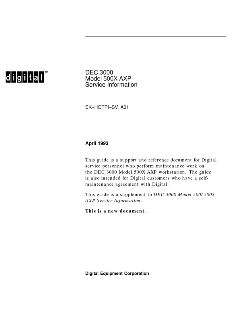
Digital Equipment DEC 3000 500X AXP Operating and installation instructions

Digital Equipment
Digital Equipment DECstation 5000 Model 200 User manual

Digital Equipment
Digital Equipment DECstation 212LP User manual
Digital Equipment
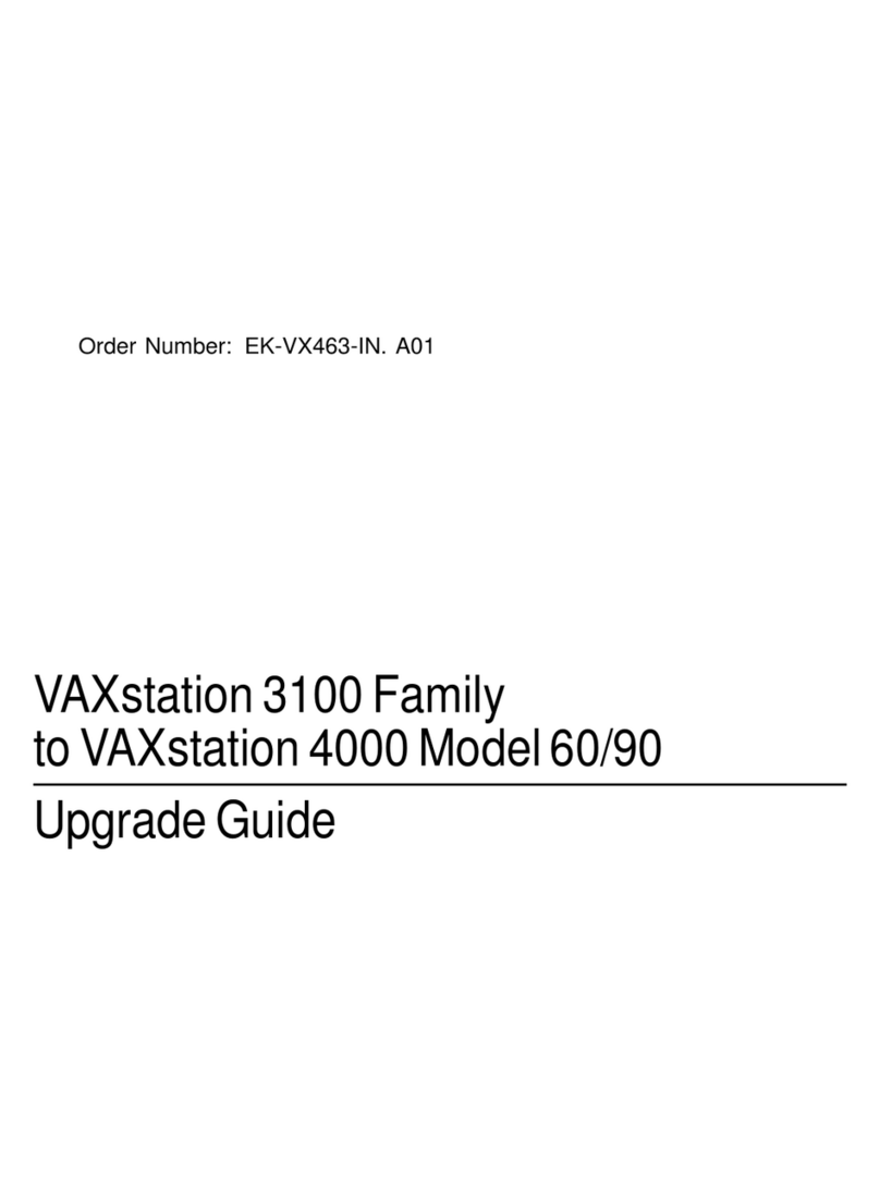
Digital Equipment VAXstation 3100 Series Installation and operation manual
Digital Equipment
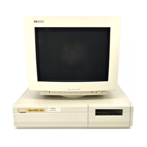
Digital Equipment MicroVAX 3100 Model 30 Quick start guide

Digital Equipment
Digital Equipment VT100 User manual
Digital Equipment
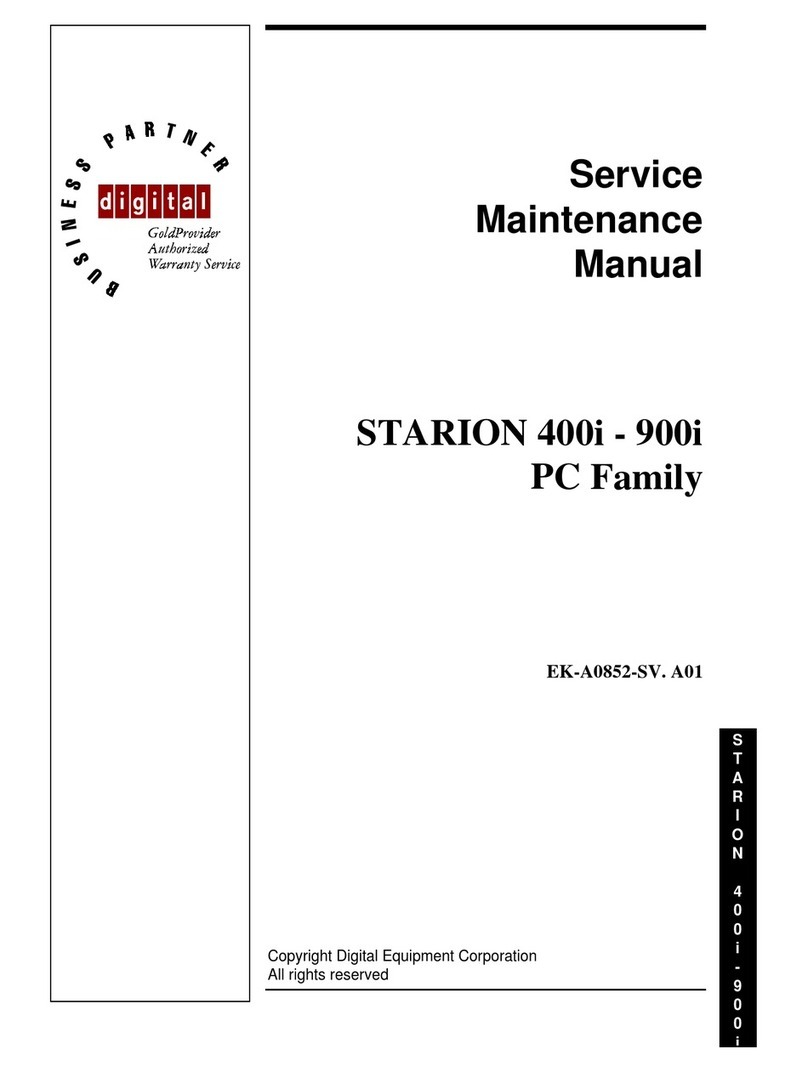
Digital Equipment Starion Series User manual
Digital Equipment
Digital Equipment VAXft Systems 810 Operating and installation instructions

Digital Equipment
Digital Equipment Venturis FX User manual
Digital Equipment
Digital Equipment VAXft 810 Service manual
Digital Equipment
Digital Equipment VAX 4000 500A User manual
Digital Equipment
Digital Equipment 7000 AXP System User manual

Digital Equipment
Digital Equipment DEC 3000 User manual
Digital Equipment
Digital Equipment DEC 3000 300 AXP Series User instructions
Digital Equipment
Digital Equipment VAX 4000 Model 500A User manual
Digital Equipment
Digital Equipment 300 Series AXP User manual

Digital Equipment
Digital Equipment STARION 200i User manual

Digital Equipment
Digital Equipment DEC 3000 500X AXP User manual
Digital Equipment
Digital Equipment microvax II 630qy User manual

Digital Equipment
Digital Equipment STARION 20 Series User manual
Digital Equipment
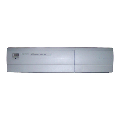
Digital Equipment VAXstation 4000 Model 60 Installation and operation manual
Digital Equipment
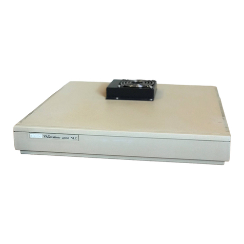
Digital Equipment VAXstation 4000/60 Operating and installation instructions
Digital Equipment
Digital Equipment DECpc LP User manual
Digital Equipment
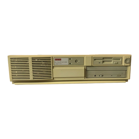
Digital Equipment Digital AlphaStation 200 Series Manual


