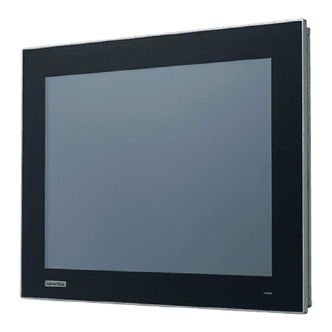
Digital Equipment FP-2500T User manual

FP-2500/FP-2600 Series
User Manual
Digital Electronics Corporation

1FP-2500/FP-2600 Series User Manual 1
1) It is forbidden to copy the contents of this manual, in whole or in part, except for the
user'spersonaluse,withouttheexpresspermissionofDigitalElectronicsCorpora-
tionofJapan.
2) Theinformationprovidedinthismanualissubjecttochangewithoutnotice.
3) Thismanualhasbeenwrittenwithcareandattentiontodetail; however,shouldyou
findanyerrorsoromissions, pleasecontactDigitalElectronicsandinformthemof
yourfindings.
4) Regardlessoftheaboveclause,DigitalElectronicsCorporationshallnotbeheld
responsibleforanydamagesorthird-partyclaimsfordamagesorlossesresulting
fromthe use ofthis product.
AllCompany/Manufacturer namesusedinthismanualaretheregisteredtrademarks of
theirrespectivecompanies.
©2004,DigitalElectronicsCorporation
Thankyou for purchasingDigital’sTFT type colordisplaypanel,the FP-2500/FP-
2600 Series unit (hereafter referred to as the FP unit or FP Series).
Pleaseread thismanual completelyto ensure thecorrect useand complete under-
standingoftheFPunit'sfunctions.
Preface
<Note>

2FP-2500/FP-2600 Series User Manual
Essential Safety Precautions
Thismanual describes safetyinstructionsfor correct useofthe FP unit.Pleasekeepthis
manual close at hand and refer to it when necessary.
Thefollowingsymbolsareused throughout this manual toensure thesafe useoftheFP
unit. Pleasebesuretofollowallinstructionsgivensincetheyexplainimportantsafety
points.
Indicatessituationswhereseverbodilyinjury,deathor
majorequipmentdamagewilloccur.
Indicates situations where bodily injury or machine
damagecan occur.
Warning
Caution
• Prior to connecting the FP-2500/FP-2600 Series (hereaf-
ter referred to as the “FP”or FP unit) unit’s power cord
terminals to the Terminal Block, be sure to check that
the FP unit’s power supply is completely turned OFF, via
a breaker, or similar unit.
• Do not use voltage levels that exceed the FP unit’s speci-
fied voltage range. Doing so may cause a fire or an elec-
tric shock.
• Since the FP unit contains high voltage parts, an electric
shock can occur when opening the unit. Therefore, be
sure to unplug the power cord before opening it.
• Do not modify or remodel the FP unit. Doing so may lead
to a fire or electric shock.
• Do not use FP unit touch panel switches in human-safety-
related or important disaster prevention situations. For
safety-related switches, such as an emergency stop
switch, be sure to use a separately installed mechanical
switch.
• Do not use the FP unit as a warning device for critical
alarms that can cause serious operator injury, machine
damage or production stoppage. Critical alarm indica-
tors and their control/activator units must be designed
using stand-alone hardware and/or mechanical inter-
locks.
Essential Safety Precautions
WARNINGS

FP-2500/FP-2600 Series User Manual 3
Essential Safety Precautions
•After the FP unit’s backlight burns out, unlike the FP unit’s
“Standby Mode”, the touch panel is still active. If the op-
erator fails to notice that the backlight is burned out and
touches the panel, a potentially dangerous machine op-
eration error can occur. Therefore, do not use FP touch
switches for the control of any equipment safety mecha-
nisms, such as Emergency Stop switches, etc. that pro-
tect humans and equipment from injury and damage.
If your FP unit's backlight suddenly turns OFF, use the
following steps to determine if the backlight is actually
burned out.
1) If your current FP application is not set to turn the back-
light OFF, and the screen has gone blank, your back-
light is burned out.
2) If your current FP application is set to turn the back-
light OFF, and if touching the screen does not cause
the display to reappear, your backlight is burned out.
• If substantial amounts of metallic dust, water or liquids
enter the FP unit, turn OFF the power supply immedi-
ately, unplug the power cord, and contact your local FP
distributor.
• When installing the FP unit, be sure to follow the instruc-
tions given in “Chapter 3 Installation and Wiring".
• Do not use the FP in an environment where flammable
gases are present, since operating the FP may cause an
explosion.
•Do not use the FP with aircraft control devices, aerospace
equipment, central trunk data transmission (communica-
tion) devices, nuclear power control devices, or medical
life support equipment, due to these devices’ inherent
requirements of extremely high levels of safety and reli-
ability.
• When using the FP with transportation vehicles (trains,
cars and ships), disaster and crime prevention devices,
various types of safety equipment, non-life support re-
lated medical devices and others, be sure to use redun-
dant and/or failsafe system designs to ensure the appro-
priate degree of system reliability and safety.
• To prevent operator injury or machine damage, be sure
to design your machine operation system so that the
machine will not malfunction due to a communication fault
between the FP unit and its PC host controller.
WARNINGS


4FP-2500/FP-2600 Series User Manual
Essential Safety Precautions
• Do not strike the FP unit’s touch panel with a hard or heavy
object, or press on the touch panel with too much force,
since it may damage the display.
• When the surface of the display screen becomes dirty or
smudged, clean the display with a cloth soaked in a neu-
tral detergent. Do not use paint thinner or organic sol-
vent.
• Do not press on the touch panel's face with sharp ob-
jects, such as a mechanical pencil or screwdriver, since
it might damage the LCD panel.
• Do not use or store the FP in direct sunlight, excessively
dusty or dirty environments, or where chemicals or their
vapors are present in the air.
• Do not restrict the FP unit's natural ventilation, or store or
use the FP in an environment that will increase the FP's
internal temperature.
• Do not use the FP in areas where sudden, large changes
in temperature may occur. These changes can cause con-
densation to form inside the unit, possibly leading to a
malfunction.
• When the product is disposed of, it should be done so
according to your country's regulations for similar types
of industrial waste.
Notes on the FP unit's Liquid Crystal Display (LCD)
• The FP unit's LCD contains a strong irritant. If the panel
is damaged and the LCD unit's liquid contacts your skin,
be sure to wash it with running water for at least 15 min-
utes. If any of this liquid should enter your eye, be sure
to flush the eye with running water for more than 15 min-
utes, and see a doctor immediately.
• The brightness of the LCD screen will depend on the
screen's current display and the LCD unit's contrast ad-
justment. Any brightness variations that result are nor-
mal for LCD displays.
• There are minute grid-points on the LCD surface. These
points are not defects.
CAUTIONS

FP-2500/FP-2600 Series User Manual 5
Documentation Conventions
• The displayed color will look different when viewed from
an angle outside the specified view angle. This is also
normal.
• Displaying a single screen image for long periods of time
can cause an afterimage to remain. To correct this, turn
the unit OFF for 5 or 10 minutes, then turn it ON again.
This phenomenon is a common attribute of the LCD unit's
and not a defect. To prevent this effect, you can:
- use the Display OFF feature, if the same image is to be
displayed for a long period of time.
- change the screen display periodically to prevent the display-
ing of a single image for a long period of time.
Documentation Conventions
Symbol Meaning
Indicatesimportantinformationorproceduresthatmustbefollowedfor
correctandrisk-freesoftware/deviceoperation.
Referstousefulorimportantsupplementalinformation.
Providesuseful orimportantsupplemental information.
*1 Indicatesusefulorimportantsupplementalinformation.
1) , 2) Indicatesstepsinaprocedure.Besuretoperform thesestepsin the
ordergiven.
The list below describes the documentation conventions used in this
manual.

FP-2500/FP-2600 Series Models/ Features
6FP-2500/FP-2600 Series User Manual
High Quality TFT Color LCD Display
The FP-2500 Series units are equipped with a 10.4 inch TFT type color LCD and the
FP-2600 Series units are equipped with a 12.1 inch TFT type color LCD. Both have
superbbrightness and wideviewingangles,notfoundin ordinarylaptop-typeTFT
LCDs.
TheFP-2500 Series unitsscreen's maximumresolutionis 640(H)X480(W) pixelsand
the FP-2600 Series units are 800(H) X 600(W) pixels. Bothe can display 260,000
colors.
Easy Installation In User Cabinets and Panels
TheFP unit's slim andcompactdesign makes installationasnap.These panels are
designedspecificallyfor IA(IndustrialAutomation)orOA(OfficeAutomation)moni-
tor. Theflatfrontpanelprovides protection equivalent to IP65f.Even withoutits
optionalprotectivecover the frontpanelishighly resistant to bothwateranddust.
Panel can be used as a Display
Since the FP is equipped with an analog RGB interface and a DVI-D Interface, it can
be connected to a PC and other similar devices easily. (The PC's dot clock frequency,
however,must be within the standard range.)
Easy-to-use Built-In Touch Panel
TheFPunit'sbuilt-in touch panel isstandard equipment,allowingtouchpaneldatato be
output to a host PC via input/output commands and an RS-232C or USB cable. This is
idealforsystemsrequiringbothtouch paneloperationanddatamonitoring.
FP-2500/FP-2600 Series Features
FP-2500/FP-2600 Series Models
The FP-2500/FP-2600 Series refers to the following FP model numbers:
Series Model
Name Model Type Power Input
Type Standards
FP2500-T12 AC
FP2500-T42-24V DC UL/c-UL/CSA Approved,
CEMarked
FP2600-T12 AC
FP2600-T42-24V DC UL/cUL Approved,
CEMarked
FP-2500 FP-2500T
FP-2600 FP-2600T

Connecting the FP to a PC/What is IP65f?
FP-2500/FP-2600 Series User Manual 7
• When a signal timing value not compatible with the FP
unit is entered, or if the entered timing value is larger than
can be displayed by the dot clock, an "OUT OF RANGE"
message is displayed. If this occurs, consult your
computer's manual and enter a value that is compatible
with this device.
• If no signal (synchronized signal) is entered, a "NO SIG-
NAL" message is displayed.
The FP-2500 Series units are designed for standard VGA mode display and the FP-
2600 Series units are designed as a standard SVGA display.
Be aware that some types of VGA/SVGA equipment may not be within the ranges
specified in this document, and, therefore, cannot be connected to the FP.
Also, if you change your PC's VGA/SVGA board, there is the possiblity that the new
board may not be able to be connected to the FP.
2.3 Interface Specifications
Connecting the FP to a PC
Thiscode indicates thedegree of ingressprotection provided fromthe front faceof the
FP, and assumes that the FP is securely mounted into a metal panel.
Thisunit'sprotectionratingofIP65fisactuallyacompositecode,consistingofthe
internationallyrecognizedBritish"IngressProtection"standard(BSEN60529:1992)-
"IP65", and the standard developed by the Japanese Electronics Manufacturer's Asso-
ciation(JEM)-"f". This code isusedinthismanual to identify thisproduct'sdegreeof
structuralresistancetoavarietyofenvironmentalelementsandthus,preventproblems
or accidents related to the inappropriate product use.
Theindividual meaningofeachcharacterofthiscodeisexplained below.
(1) Designatesthetypeof protection provided.
(2) Indicates the degree of protection provided to the human body by the unit, and the
degreeofprotection provided bytheunit'sfrontfacefromparticles/dustintrusion
intotheinterioroftheunit.
Here,"6"indicatesthattheunit iscompletelyprotectedfrom dustintrusion.
(3) Indicates the degree of protection provided by the unit's front face from water
intrusionintotheinterioroftheunit.
Here,"5"indicates that theunitisprotected from water intrusionfromadirect water
jet.
(4)Indicates the degreeof protection providedby the unit'sfrontface fromoilparticle
intrusionintotheinterioroftheunit.
Here,"f"indicatesthattheunitiscompletelyprotectedfromoilintrusionviaeitheroil
particlesoroilsplashesfrom any direction (to thefront panel).
IP 6 5 f
(1) (2) (3) (4)
What is IP65f?

8FP-2500/FP-2600 Series User Manual
Package Contents
The FP unit's packing box contains the items listed below. Please check to be sure each
itemisincludedandisnotdamaged.
FP unit (1) CD-ROM (1)
(FP2500-T12/FP2600-T12/ (FP-2500/FP-2600 Series User Manual &
FP2500-T42-24V/FP2600-T42-24V) TouchPanelCommunicationPrograms
For MS-DOS®)
Installation Gasket (1) Installation Fasteners (4)
(Attached to the FP unit)
Installation Guide (1) USB Cable Strap (1)
(Japanese/English)
Theseitemshaveallbeencarefullypacked with special attention to productquality. However,
shouldyoufindanythingdamagedormissing,pleasecontactyourlocalFPdistributorimmedi-
atelyforprompt service.
Package Contents
Installation
Guide

UL/c-UL/CSA Application Notes/CE Marking Notes
FP-2500/FP-2600 Series User Manual 9
UL/c-UL/CSA Application Notes
The FP2500-T42-24V/FP2600-T42-24V units are UL/c-UL listed products (UL File No.
E182139).
TheFP conforms as acomponentto the followingstandards:
UL508 Industrial Control Equipment
UL1604 Electrical Equipment for use in Class 1 & 2 - Division 2, and Class III
Hazardous(classified)locations.
CAN/CSA-C22.2, No.1010-1 Measuement and Control Equipment Safety require-
ments for electrical equipment for measurement and
laboratory use.
FP2500-T42-24V (UL Registration Model No.:3280033-02)
FP2600-T42-24V (UL Registration Model No.:3280033-04)
<Cautions>
BeawareofthefollowingitemswhenbuildingtheFPintoanend-useproduct:
• The FP unit's rear face is not approved as an enclosure. When building the FP unit into an end-
use product, be sure to use an enclosure that satisfies standards as the end-use product's overall
enclosure.
• The FP unit must be used indoors only.
•Thisunitshould be installed inthefrontfaceofa metal panel.
•If theFP unit isinstalled soas to coolitself naturally, besure to mountit ina vertical panel.Also,
be sure that the FP unit is installed at least 100 mm away from any adjacent structures or
machineparts. Iftheseconditions arenot met, theheat generated bythe FP unit'sinternal
componentsmay causetheunit tofail to meetUL standards.
UL1604 Conditions of Acceptability and Handling Cautions:
1.Power,inputand output (I/O)wiringmust be in accordancewithClass I, Division2wiring
methods - Article 501- 4(b) of the National Electrical Code, NFPA 70 within the United
States, and in accordance with Section 18-152 of the Canadian Electrical Code for units
installedwithinCanada.
2. Suitable for use in Class I, Division 2, Groups A, B, C and D, Hazardous Locations.
3.WARNING:Explosionhazard-substitutionofcomponentsmayimpairsuitabilityforClassI,
Division2.
4. WARNING: Explosion hazard - when in hazardous locations, turn power OFF before replac-
ingorwiringmodules.
5.WARNING: Explosionhazard - do not disconnectequipment unlesspower hasbeen switched
OFF, or the area is known to be non-hazardous.
6.WARNING: Explosion hazard- donot connect/disconnect equipmentunless area isknown to
be nonhazardous.
The FP2500-T42-24V/FP2600-T42-24V are CE marked products that conform to EMC direc-
tives EN55011 Class A and EN61000-6-2.
FordetailedCEmarkinginformation,pleasecontactyourlocalFPdistributor.
CE Marking Notes

10 FP-2500/FP-2600 Series User Manual
CD-ROM Data
CD-ROM Data
The following data and programs are contained in the FP-2500/FP-2600 Series unit's
CD-ROM.
FP2000-MMCD-02
[Manual] User Manual
[Eng]fp2000e.pdf
[Jpn]fp2000j.pdf
[Reader] Acrobat®Reader
[Eng] ar505enu.exe
[Jpn]ar505jpn.exe
[Utility] Utility Setup <Supported OS>
[Touch] Touch Panel Communication Program *1 MS-DOS®
FPATPH.CAL
FPATPH.EXE
FPCALIB.EXE
*1 These programs are only for MS-DOS®and FP-2500 series unit. When using
Windows®95, WindowsNT®4.0, Windows®98, Windows®2000 and Windows®XP,
the Mouse Emulator V2 (PL-TD000) is required.
1.2 Optional Equipment
Therevisionversioncanbedeterminedbytheidentificationlabelorrevisionstickers
thatare placed onthe main unitof the FP. Thecharactersand numeralsinthe "REV"
area that are replaced with asterisks (*), or marked with a marker indicate the revision
version.
Inthe example below,the asterisks "*"areplaced at positions "D","1",and "2", which
indicatestherevisionversionas"D, 1, 2".
Identification Label
Revision Version

Table of Contents
FP-2500/FP-2600 Series User Manual 11
Table of Contents
Preface.....................................................................................................................1
Essential Safety Precautions.................................................................................2
Documentation Conventions.................................................................................5
FP-2500/FP-2600 Series Models ............................................................................6
FP-2500/FP-2600 Series Features .........................................................................6
Connecting the FP to a PC.....................................................................................7
What is IP65f? .........................................................................................................7
Package Contents ..................................................................................................8
UL/c-UL/CSA Application Notes ............................................................................9
CE Marking Notes ...................................................................................................9
Revision Version...................................................................................................10
CD-ROM Data ........................................................................................................10
Chapter 1 Introduction
1.1 System Design ............................................................................ 1-1
1.2 Optional Equipment................................................................... 1-2
Chapter 2 Specifications
2.1 General Specifications .............................................................. 2-1
2.1.1 Electrical ........................................................................................2-1
2.1.2 Environmental.................................................................................2-2
2.1.3 Structural .......................................................................................2-2
2.2 Functional Specifications .......................................................... 2-3
2.2.1 Performance...................................................................................2-3
2.2.2 Display...........................................................................................2-3
2.3 Interface Specifications............................................................. 2-4
2.3.1 AnalogRGBInterface ....................................................................2-4
2.3.2 DVI-DInterface.............................................................................2-7
2.3.3 RS-232C Interface.........................................................................2-9
2.3.4 USBInterface ..............................................................................2-10

Table of Contents
12 FP-2500/FP-2600 Series User Manual
2.4 Cable Diagrams ....................................................................... 2-11
2.4.1AnalogRGBInterfacePinConnections(Optionalcable)................ 2-11
2.4.2DVI-D Interface PinConnections(Optional cable) ........................2-12
2.4.3 RS-232C Interface Pin Connections (Optional cable) ....................2-13
2.4.4 USB Interface Cable Pin Connections (Option cable) ....................2-13
2.5 Names and Functions of FP Parts ......................................... 2-14
2.6 FP Dimensions.......................................................................... 2-15
2.6.1 ExternalDimensions ....................................................................2-15
2.6.2 ExternalDimensions(withInstallationFasteners) ...........................2-16
2.6.3 InstallationFasteners ....................................................................2-17
2.6.4 FPPanelCutDimensions .............................................................2-17
Chapter 3 Installation and Wiring
3.1 Installation...................................................................... 3-1
3.1.1 InstallationProcedures....................................................................3-1
3.2 Wiring Cautions......................................................................... 3-6
3.2.1 Connecting the Power Cord ...........................................................3-6
3.2.2 ConnectingtheUSBCableStrap Attachment .................................3-8
3.2.3 Connectingthe PowerSupply ........................................................3-9
3.2.4 Precautions: Grounding ................................................................3-10
3.2.5 Precautions: Input/OutputSignalLines .........................................3-10
Chapter 4 Setting up and Adjusting the FP unit
4.1 Operation Mode Setup .............................................................. 4-1
4.1.1 Dip Switch Preset Settings and Adjustments ...................................4-1
4.1.2 Status of Front LED in Operation Modes........................................4-2
4.2 Screen Display Adjustment....................................................... 4-2
4.2.1 CalibrationofOSDDisplayPosition ...............................................4-2
4.2.2 OSDSetting Icons .........................................................................4-3
4.2.3 OSDSettingItemDetails................................................................4-4

Table of Contents
FP-2500/FP-2600 Series User Manual 13
Chapter 5 Touch Panel Data
5.1 Touch Interface Data................................................................. 5-1
5.2 Touch Panel Communication Programs For MS-DOS® .... 5-4
5.2.1 FPATPH.EXE (TouchPanelHandler) ............................................5-4
5.2.2 FPCALIB.EXE (TouchPanelDataFPCalibration) ........................5-8
Chapter 6 Troubleshooting
6.1 Troubleshooting ......................................................................... 6-1
6.1.1 PossibleDeviceProblems...............................................................6-1
6.1.2 No Display ....................................................................................6-2
6.1.3 Touch Panel Does Not Respond ...................................................6-4
6.2 Error Message ........................................................................... 6-5
6.2.1 Error Message List .......................................................................6-5
Chapter 7 Maintenance
7.1 Regular Cleaning...................................................................... 7-1
7.1.1 CleaningtheDisplay .......................................................................7-1
7.1.2 InstallationGasketReplacement......................................................7-2
7.2 Periodic Check Points ............................................................. 7-3
7.3 Backlight Replacement............................................................ 7-4
7.3.1 ReplacingGP577RT-BL00-MS .....................................................7-6
7.3.2 ReplacingPS600-BU00 .................................................................7-8
7.3.3 ReplacingCA3-BLU12-01 ..........................................................7-10

14 FP-2500/FP-2600 Series User Manual14
Memo

1.1 System Design
1-1FP-2500/FP-2600 Series User Manual
The FP unit’s dip switches set the type of communication method used for sending
touch data and commands (USB or RS-232C), and also for outputing image signals
(DVI-D or Analog RGB).
4.1.1 Dip switch setting
USB Interface Cable
FP-US00<5m>
A-B type Cable
For Touch data and Command transmission
RS-232CInterface Cable
FP61V-IS00-O<5m>
Straight Cable : Dsub 9-pin female
For Touch data and Command transmission
DVI-DCable
FP-DV01-50<5m>
For image signal output
Analog RGB Interface Cable
FP-CV00<2.5m>,FP-CV01<5m>
FP-CV02-45<4.5m>
For image signal output
Chapter 1
Introduction
1. System Design
2. Optional Equipment
1.1 System Design
PS-2000B
or
Windows®compatible PC
FP unit
The FP can be connected to Pro-face's PS-2000B or to a Windows®compatible PC.
Image Signal Output
Touch Panel Communication

1.2 Optional Equipment
1-2 FP-2500/FP-2600 Series User Manual
1.2 Optional Equipment
AlloptionalitemslistedbelowareDigitalElectronicsCorporationproducts.
Item Model Number Description
RS-232C Cable FP61V-IS00-O (5m)
Serial interface cable used for touch panel data
transmission between the host and the FP or
command transmission to the FP. This is a
straight Dsub 9-pin female cable.
Analog RGB Cable FP-CV00 (2.5m)
FP-CV01 (5m)
FP-CV02-45 (4.5m)
Analog RGB interface cable used when image
signals are output to the FP from the host.
(Dsub 15-pin male).
USB Cable FP-US00 (5m)
USB interface cable used for touch panel data
transfer between the host and the FP or
command transmission to the FP. A-B type
cable.
DVI-D Cable FP-DV01-50 (5m) Digital Visual Interface cable used to send the
image signal from the host to the FP. XGA
specification DVI-D 24-pin male.
Cables
Maintenance Parts
Item Model Number Corresponding FP Rev. Description
Installation
Fasteners GP070-AT01 FP-2500 Series
FP-2600 Series -Metal installation
fasteners.
Rubber Gasket GP570-WP10-MS FP-2500 Series
FP-2600 Series -
Replacement rubber
gasket, used when
installing the FP. Same as
the FP unit's original
gasket.
Screen Protection
Sheet PSL-DF00 FP-2500 Series
FP-2600 Series -
Disposable, dirt resistant
sheet for the FP unit's
screen. The FP unit's
touch panel can be used
with this cover
sheet attached.
(5 sheets/set)
GP577RT-BL00-MS FP-2500 Series - Replacement backlight for
FP-2500 Series units.
FP2600-T12 Rev.1 is not
marked.*1
FP2600-T42-24V Rev.1 is not
marked.*1
FP2600-T12 Rev.1 is
marked.*1
FP2600-T42-24V Rev.1 is
marked.*1
Replacement backlight for
FP-2600 Series units.
Backlight PS600-BU00
CA3-BLU12-01
*1The corresponding backlight unit differs depending on FP-2600 Series unit's
marked Revision.
For more information on how to determine the revision version,
see "Revision Version" (Page 10).

1.2 Optional Equipment
1-3FP-2500/FP-2600 Series User Manual
Item Model Number Description
Mouse Emulator V2 *1 PL-TD000 Mouse emulation software for the FP.
Available Software
*1 OS can be Windows®95, WindowsNT®4.0, Windows®98, Windows®2000 or
Windows®XP .

1.2 Optional Equipment
1-4 FP-2500/FP-2600 Series User Manual
Memo

FP-2500/FP-2600 Series User Manual 2-1
2.1.1 Electrical
1. General Specifications
2. Functional Specifications
3. Interface Specifications
4. Cable Diagrams
5. Names and Functions of FP
Parts
6. FP Dimensions
Chapter 2
Specifications
2.1 General Specifications
Rated Voltage AC100VtoAC 240V
Rated Voltage Range AC85Vto AC 264V
Rated Frequency 50/60Hz
Rated Frequency Range 47 Hzto 63 Hz
Allowable Voltage Drop 20msorless
Power Consumption 50VA(ACIN100V)/85VA(ACIN 240V)
Voltage Endurance AC1500V20mAfor1 minute
(between chargingand FG terminals)
Insulation Resistance 10MΩorhigheratDC500V
(between chargingand FG terminals)
FP2500-T12/FP2600-T12
FP2500-T42-24V/FP2600-T42-24V
Rated Voltage DC24V
Rated Voltage Range DC19.2 to DC28.8V
Allowable Voltage Drop 10msorless
In-rush Current 30Aorless
Power Consumption 50Worless
Voltage Endurance AC1000V20mAfor1 minute
(between chargingand FG terminals)
Insulation Resistance 10MΩorhigheratDC500V
(between chargingand FG terminals)
This manual suits for next models
1
Table of contents
Other Digital Equipment Industrial Monitor manuals
Popular Industrial Monitor manuals by other brands

Austin Hughes
Austin Hughes RP-F821 user manual

Advantech
Advantech IDS-3319 Series user manual

VETEC
VETEC P1001 Series manual

Curtis
Curtis enGage IV manual

Moxa Technologies
Moxa Technologies MD-215 Series Quick installation guide

Total Controls
Total Controls QuickPanel jr. QPKSxDN0000 Series installation instructions