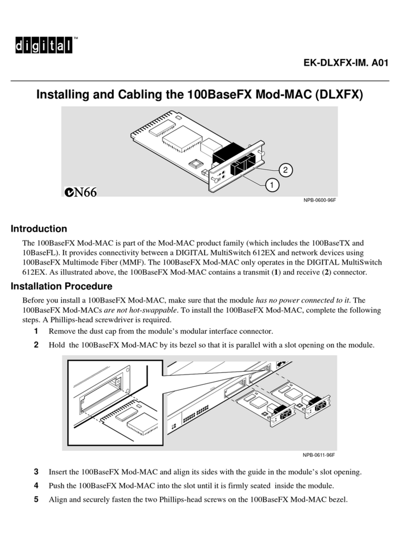
3Insert the 10BaseFL Mod-MAC and align its sides with the guide in the module’s slot opening.
4Push the 10BaseFL Mod-MAC into the slot until it is firmly seated inside the module.
5Align and securely fasten the two Phillips-head screws on the 10BaseFL Mod-MAC bezel.
6Insert the transmit and receive 10BaseFL Mod-MAC connectors into the transmit (1) and receive (2)
10BaseFL Mod-MAC port connectors, respectively.
When the module is powered on, the following 10BaseFL Mod-MAC LEDs become operational:
Reference
If the LEDs do not operate as described, refer to the troubleshooting information in the DIGITAL MultiSwitch
612EX Installation and Configuration manual. The manual provides safety and product specification information.
The informationisalso available onthe DigitalEquipmentCorporationNetworkProducts Engineering Home Page
on the World Wide Web at the following addresses:
North America: http://www.networks.digital.com
Europe: http://www.networks.europe.digital.com
Australia: http://www.digital.com.au/networks
© Digital Equipment Corporation 1997. All rights reserved.
Digital, and the DIGITAL logo are trademarks of Digital Equipment Corporation.
Item Name Description
1 Activity LED Flickers in response to traffic on this port.
2 Port Status Is turned off if there is no connection; blinks if the port has
been management disabled.
NPB-0607-96F
1
2
NPB-0608-96F
1
2
