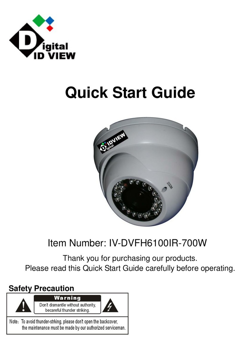
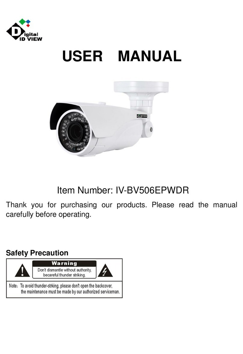
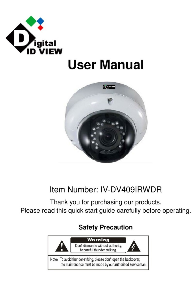
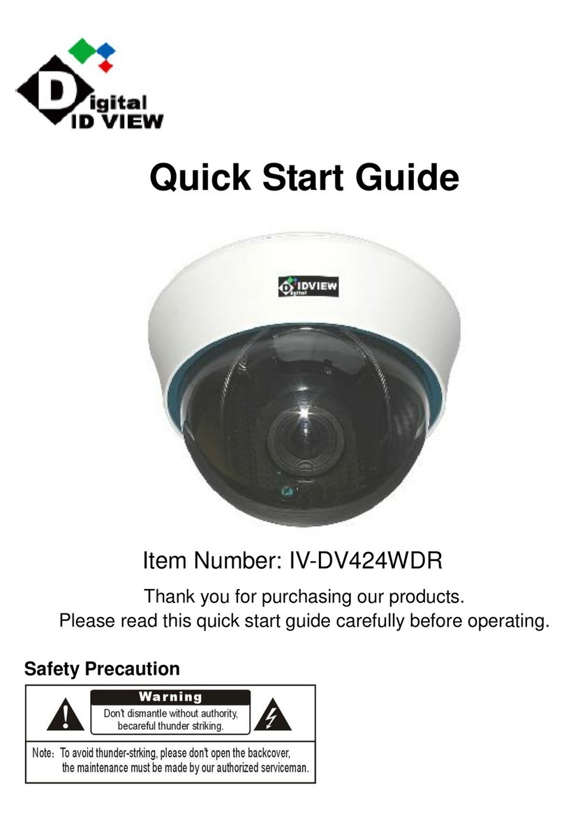
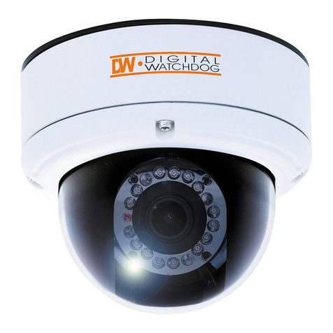
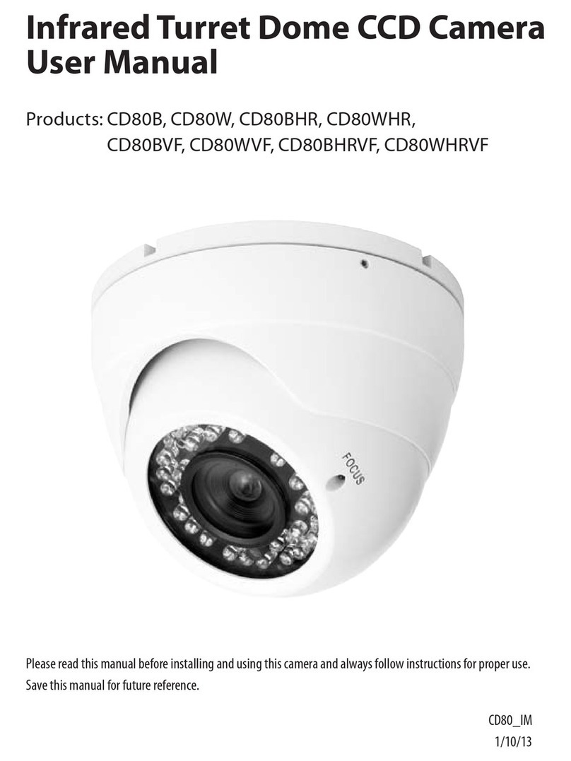
Digital ID View Mega-Pix IV-LC-D331MP User manual

Before trying to connect or operate this product, please read this manual completely
INSTALLATION &
OPERATION MANUAL
Mega-Pix IP Fixed Dome

1
Table Of Contents
SAFETY PRECAUTIONS .............................................................................3
1. PRODUCT FEATURES.............................................................................4
1.1 PRODUCT INSTRUCTIONS .....................................................................4
1.2 PRODUCT FEATURES ...........................................................................5
2. DESCRIPTION OF THE DEVICE .............................................................8
2.1 NAME OF PARTS ..................................................................................8
2.2 THE CONNECTORS ..............................................................................9
2.3 THE USB FUNCTION ..........................................................................10
2.4 POE (POWER OVER ETHERNET).........................................................11
2.5 LENS ADJUSTMENT ............................................................................12
2.6 INSTALLATION ....................................................................................13
3. UPDATING SYSTEM SOFTWARE ........................................................15
4. Network Configuration..........................................................................17
4.1 CABLE CONNECTIONS........................................................................17
4.2 CONFIGURE YOUR IP CAMERA NETWORK SETTINGS ...........................17
4.2.1 Enable DHCP Function.....................................................................................................................17
4.2.2 Set IPAddress ...................................................................................................................................18
4.3 TCP/IP COMMUNICATION SOFTWARE .................................................19
4.4 TCP/IP INSTALLATION .......................................................................21
4.5 TCP/IP CONFIGURATION SETTING ......................................................22
4.6 CONNECTION TESTING.......................................................................23
5. Operating Instructions for Image Software and Network..................25
5.1 MICROSOFT INTERNET EXPLORER ......................................................26
5.1.1 Connecting the IP camera ................................................................................................................26

2
5.1.2 Live Video........................................................................................................................................27
5.1.3 Setup.................................................................................................................................................31
5.2 THE IP CAMERA CMS (CENTRAL MANAGEMENT SYSTEM)...................82
5.2.1 Introduction to the CMS ..................................................................................................................82
5.2.2 Install the CMS in your PC..............................................................................................................83
5.2.3 Login the IP Camera software..........................................................................................................84
5.2.4 Operation..........................................................................................................................................86
6. ADVANCED OPERATION....................................................................100
7. SPECIFICATIONS.................................................................................102
8. Functions of client PC.........................................................................103
APPENDIX 1. –IP camera UPnP How To................................................104
APPENDIX 2. –The ARP function ...........................................................114
APPENDIX 3. –Register as a DDNS member ........................................116
APPENDIX 4. –MPEG4 Bit Rate Lookup Table of IP camera...............120
APPENDIX 5. –PoE Installation Method ................................................121
APPENDIX 6. –FAQ..................................................................................124

3
SAFETY PRECAUTIONS
All the following safety and operational instructions to prevent harm or injury to the operator(s) or
other persons should be read carefully before the unit is activated.
WARNING
To prevent fire or shock hazard, avoid exposing this unit to rain or moisture.
Do not block ventilation openings.
Do not place anything on top of the unit that might spill or fall into it.
Do not attempt to service this unit yourself, as opening or removing covers may
expose you to dangerous voltage or other hazards. Please refer all servicing to
your distributor / retailer.
Do not use liquid cleaners or aerosols for cleaning.
To prevent fire or electric shock, do not overload wall outlets or extension cords.
This unit must be grounded to reduce the risk of electric shocks.
CAUTION
RISK OF EXPLOSION IF BATTERY IS REPLACED BY AN INCORRECT TYPE.
DISPOSE OF USED BATTERIES ACCORDING TO THE INSTRUCTIONS.

4
1. PRODUCT FEATURES
1.1 Product Instructions
The freshly designed MJPEG and MPEG4 multi-stream compression codec Mega-Pix IP Fix ed
Dome provides simultaneous video codec streams of MJPEG and MPEG4. This IP camera not
only supports the 30 / 25 fps frame rate ( in the NTSC / PAL system ), motion detection and a built-in
microphone, but also the day and night, pre- and post-alarm, and PoE functions. The images from
this device have no interlace, and the camera sensor used is the 1/3" VGA CMOS sensor.
In addition, this IP camera hosts the powerful multi profile function which enables the simultaneous
use of different rates of resolution while allowing two video codecs to connect with computers at the
same time. Apart from this, the camera brings you the user-friendly PnP operations, and captures
alarm and scheduled recordings by using an SD card. Besides, the IP camera is equipped with a
vandal-proof body for day and night surveillance. With the specific 3-axis mechanical design, this
dome camera provides a flexible installation for ceiling or wall mounting, and wide angled viewing
which pans 360°and tilts 180°.
This new generation mega-pix IP fixed dome offers a more progressive digitalized image
technology and a user-friendly, controlled interface in the IE Browser to thoroughly update your
surveillance capabilities.

5
1.2 Product Features
Camera
Image sensor SONY 1.3M CMOS Sensor (IMX035)
Image co-processor Sony CMOS Sensor IMX035
Lens type CS (C mount adaptor can be used)
Shutter time AES:1/30 ~1/1000
Sensor resolution 1280 x 960
Auto iris type DC drive
S/N Ratio 50db with AGC off
Day & Night Mechanical IR filter
Day & Night mode Auto/Day/Night/Schedule
Video Signal
Video output type BNC
Video output level 1.0 Vpp +/-10% 75Ω, composite, Negative (BNC unbalanced)
Synchronization Internal
Video Codec
Video compression MPEG-4 Part2 (ISO/IEC 14496-2)
Motion JPEG
Resolutions 960P/ 720P / 640 x 480 / 320 x 240 /160 x120 (NTSC : PAL / 60Hz : 50Hz)
Video streaming Simultaneous MPEG-4 (960P/ 720P / 640 x 480 / 320 x 240 /160 x120)
Video Codec – MPEG4
MPEG-4 Frame rate Up to 30 fps at 1280 x 960
MPEG-4 frame rate control Yes
Customized MPEG-4 bit
rate Yes
MPEG-4 bit rate control Yes
MPEG-4 quality level 5
Video Codec – MJPEG
Motion JPEG frame rate Up to 30 fps at1280 x 960
Motion JPEG rate control Yes
Motion JPEG quality level 5
Audio Signal
Number of tracks Mono 1 channel
Audio sample rate G.711 / G.726
Audio output 1K ohms
Audio input Built-in Microphone / LINE in10k ohms 1.0Vpp
2-Way Audio Full-duplex /Half –duplex/audio off
Image
White Balance Auto / Outdoor / Indoor / Fluorescent
Max AGC control 8X,16X,32X,64X
Mirror Yes
Flip Yes
Exposure Time Adjustable
High speed shutter 1 / 8000 second
Saturation Adjustable
Sharpness Adjustable
Contrast Adjustable
WDR level Adjustable
Brightness Adjustable
Privacy Area Programmable 3 independent zones
Motion Detection Programmable 96 independent zones
Motion Detection Sensitivity 5 levels
Customized motion detection sensitivity Yes
Digital PTZ Yes

6
OSD IP Address/Date/Time/ICON
Timestamp Title/Date/Time
Software Platform
Operation System Linux-based system
System Integration
System Requirement Microsoft Windows XP
Remote Access Software Microsoft Internet Explorer 6.0 or above
Network API SDK/CGI/DLL
Recording Software 16 channel free-bundled CMS
Alarm
Alarm triggers Motion Detection, Schedule, Alarm input, System Boot
Alarm application SD recording, SMTP, FTP, Network Storage, CMS recording
Alarm duration Programmable
Schedule counts 3
Hardware
Processors Texas Instruments DaVinci
High performance 32-bit RISC CPU
DDRII memory DDRII 1Gbit
Flash memory 256Mb
Real-time clock Built-in
Real-time clock battery Built-in
Watchdog Built-in
Firmware upgrade SD Card/HTTP
Fan Yes
Heater Yes
Approvals
FCC Yes
CE Yes
RoHS Yes
Power
DC 12V Yes Max (TBD Watt)
AC 24V Yes
PoE Power over Ethernet (IEEE 802.3af)
Physical Property
Height 50mm
Width 62mm
Length 95mm
Weight 360 g
MTBF 1350000 Hours
Operating Temperature -20℃to 50℃(-4℉to 122℉)
Operations Humidity 30% to 80 %
Storage Temperature -20℃to 60℃(-4℉to 140℉)
USB
Type 2.0 * 1
Capacity 24Mbit
Network settings configurable Yes
Network
Ethernet Ethernet (10/100 Base-T), RJ-45 connector
MDIX Yes
Security
2-Level password protection
IP address filtering
User access log
Protocol HTTP, HTTPS, TCP, RTSP, RTP, RTCP, DHCP, UPnP, ARP, DNS,
DDNS, NTP, PPPoE, 3GPP, FTP, SMTP
Management console Full function
Throughput 19M bit/second
Bandwidth control Yes
Simultaneous users 8

7
DDNS Dyndns
IE recording support Yes
Storage
SD Card Support MMC/SD/SDHC 2.0 32MB~32GB
Pre-alarm Yes
File system FAT32/16/12
Recording format JPG/AVI
Network play-back Yes
SD card brand verified A-Data, PQI, Toshiba, Transcend, A-Pacer, Photo Fast
Multi-lingual User Interface
Languages
English, Traditional Chinese, Simplified Chinese, Czech, Dutch
Finland, French, German, Italian, Polish, Portuguese, Spain, Swedish,
Hungarian, Rumanian, Turkish
Device Indicator
Ethernet Link Yes
Ethernet Active Yes
System Operation Yes
System Warning Yes
Accessories
Accessories
USB cable
CD-Rom
C-Mount ring
Power Adapter
Quick installation guide
PTZ Support
Protocol Pelco-D /Pelco-P
I/O Ports
USB 2.0 x1
DHCP/Static IP switch 1
DC IRIS/AES switch 1
Factory Reset Yes
RS-485 Yes
Alarm input 1
Alarm output 1
Audio I/O IN *1 / OUT *1
Ground 1
DC-OUT 1
The Surface:

8
2. DESCRIPTION OF THE DEVICE
2.1 Name of parts
1. SD CARD slot:
This is used for system software updating and archiving / accessing critical images.
2. 5pin MINI USB Port:
You can use a USB device cable to connect the IP camera to the USB port on the PC.
3. RESET :
Recover to factory default.
3

9
2.2 The Connectors
1. VIDEO OUT BNC Connector:
The connector provides the unit’s composite video signals to a monitor.
2. ETHERNET 10/100 Connector (PoE):
This is a standard RJ-45 connector for 10/100 Mbps Ethernet networks. PoE (Power over
Ethernet) function: Provides power to the device via the same cable as used for the network
connection.
3. DC12V :
A DC 12V inlet that connects to an external power supply.
4. I/O-B 4 PIN:
5. I/O- A 4 PIN:
6. AC24V 2 PIN:

10
2.3 The USB function
By connecting the IP camera with a PC via the USB connector, the IP camera can provide two
different functions.
1. Insert an SD card: As a card reader.
Insert an SD card into the IP camera, then connect to the PC. You might transfer files between
the SD card and the PC. Once you've connected your IP camera to your computer, the
Windows system will detect the connection and ask you what you want to do with your SD
card.
In other words, if the user connects the IP camera with an SD card and the PC via the USB
connector, the IP camera can be used as a normal card reader.
2. Remove an SD card: As a configuring tool.
Before using the USB configuration setting page, please remember to remove the SD card or
your PC will read the SD card and won’t show this window.
DHCP ON
DHCP OFF
(default)
NOTE: After changing the settings, please click the “Apply” button. All of the options
will be effective after removing the USB connector.
NOTE: After the IP address has been changed, please unplug the network cable, then
plug it once again to make sure the network connection is in normal mode.
Network
Setting

11
2.4 PoE (Power over Ethernet)
These technologies will enable the development of new networked appliances, by providing
power as well as data over existing Ethernet cables.
The Summary Comparison of PoE Standards (Table 1) is listed as follows.
Table 1. Summary Comparison of PoE Standards
SOURCE
Ethernet RJ-45 connector pin number * LOAD
STANDARD Source
Voltage 1 2 3 4 5 6 7 8 Load
Voltage
DC Load
Connector
REMARKS
IEEE
802.3af
using data
pairs
48 V DC,
protected
RX,
DC+
RX,
DC+
TX,
DC- spare spare TX,
DC- spare spare (embedded)
Industry
Standard
for
embedded
PoE
IEEE
802.3af
using spare
pairs
48 V DC,
protected RX RX TX DC+ DC+ TX DC- DC- (embedded)
Industry
Standard
for
embedded
PoE
The compatible PoE Hubs (Table 2), which can be used with the unit, are shown in the tables
below.
Table 2. Compatible PoE HUB
Manufacturer Model Port Note
FSP-804P 4 Port PoE HUB
PLANET POE-151 1 Port PoE HUB
D-Link DWL-P200 1 Port PoE HUB
Connect to a PoE HUB
The Standard RJ-45 PIN configuration for connecting with a PoE HUB is shown below.

12
2.5 Lens adjustment
Before adjusting the lens, the user has to remove the cover of the dome. 1) Loosen the screws
holding the camera mount and then 2) carefully lift the cover up. After all adjustments
completion, attach the dome cover to the camera.
Focus adjustment:
(1) Loosen the fixing screws on the Zoom ring and Focus ring.
(2) Adjust the angle of view with the Zoom ring and adjust the focus with the Focus ring for
the best picture resolution.
(3)After lens adjustment completion, tighten both the Zoom ring fixing screw and the Focus
ring fixing screw.
Zoom ring
Focus ring

13
2.6 Installation
Hardware Installation
Follow the steps below to install the dome network camera:
Figure 1.
Figure 2.
Step 1.
Secure the mount base to the
wall / ceiling and rotate the
mount cap into the mount base
( see figure 1 ).
Step 2.
Use the 3 rotating screws to fix
the dome camera bottom tightl
y
( see figure 2 ).

14
Figure 3. Step 3.
Pass the cable through the
mount base, then rotate the
dome camera into the cap. The
installation is complete ( see
figure 3 ).

15
3. UPDATING SYSTEM SOFTWARE
Please follow the instructions and the diagram below to set up the system.
If the system software of the IP camera needs to be upgraded, please take the following steps to
safely process it.
Important: Before carrying out the following procedures, please ensure the SD card is
working and the file of the system firmware is intact
1. Create a directory named UPGRADE (upper-case or lower-case letters are no difference) in the
SD card if it does not exist.
2. Copy the file of UPDATE.BIN to the UPGRADE -directory.
3. If the IP Camera is running, please power it off first.
4. Insert the SD CARD into the IP Camera.
5. Remove the Ethernet cable from the RJ-45 port and then power on the IP Camera.
6. In 5 to 10 seconds, a message reading "UPDATE PROCESSING" will show up on the screen on
a blue background; if not, please check out steps 1 to 6 carefully or else inform your technical
support while ignoring the following steps.
7. DO NOT power off the IP Camera while this update process is running until the message
"UPDATE OK RESET PLEASE" appears on the screen; it might take 15 to 30 seconds to
appear.
8. If the message "UPDATE NG RESET PLEASE" appears rather than "UPDATE OK RESET
PLEASE", please write down the error messages shown on the screen and inform your
technical support, while ignoring the following steps.
9. Power off the IP Camera when this update process is finished, then remove the SD card from
the IP Camera.
10. Reconnect the Ethernet cable to the RJ-45 port if necessary.
11. Power ON the IP Camera and it will work normally if the entire update procedure goes correctly.
12. Verify the version of the system software.

16
WARNING:
Steps 1 to 2 have to be done on a PC.
Make sure the file of UPDATE.BIN is a correct one in step 2, or the IP Camera will not
work normally after being updated.
If the power of the IP Camera is suddenly lost in step 7, please remove the SD card
first and turn on the IP Camera next to test its operation. If the IP Camera remains
working normally, please go back to step 3; otherwise, please inform your technical
support.
In step 9, if the SD card is not removed and the IP Camera does not get online as well,
the updating process must be repeated again after rebooting the IP Camera.
Make sure that the SD card is inserted in a correct position in step 4, or the IP Camera
will suffer permanent physical damage.
If the message "CSUM ERROR" appears in step 7, it implies a problem in the file of
UPDATE.BIN.
Don’t interrupt the process while the unit is updating itself; proceed with an SD
card not including any system software of the unit, or else the unit will crash.

17
4. Network Configuration
4.1 Cable Connections
Please follow the instructions below to connect your IP camera to a computer or a network and to
choose a proper RJ-45 cable configuration for connections.
Physical specifications of the RJ-45 cable for Ethernet
Wire Type Cat. 5
Connector Type RJ-45
Max. Cable Length 100 m
Hub Wiring Configuration Straight Through
PC Wiring Configuration Straight Through
4.2 Configure Your IP Camera Network Settings
Upon connecting with the network hardware, you need to activate the network function and
configure the proper network settings of the IP camera.
4.2.1 Enable DHCP Function
This function can onlywork if the LAN, which the unit is connected to, has a DHCP server. If the
DHCP server is working, please turn on to use the DHCP protocol; now the IP CAMERA will
obtain an IP address automatically from the DHCP server. In this instance, please skip section
4.2.2 (Set IP address) and follow section 4.3 (TCP/IP Communication Software).
Note: T he IP D ome camera so ftware default s etting is DH CP OF F. Users ca n buil d the
camera working en vironment with a st atic IP address. T he defa ult st atic I P is
192.168.1.168. You can set a n IP a ddress f or t he camera if t he L AN u nit isn’ t
connected to a DHCP ser ver. Or turn on t o u se the DHCP p rotocol if t he D HCP
server is working in the LAN, The camera will obtain an IP address automatically
from the DHCP server. The camera is linked by its Video Out connection via a BNC
connector to a monitor's Video In c onnection. If this connection is there, you can
see som e inf ormation on t he monitor screen, such as t he camera fac tory d efault
Static IP address.

18
4.2.2 Set IP Address
You need to set an IP address for the unit if the LAN unit isn’t connected to a DHCP server.
Otherwise, please follow the instructions given below:
Set the IP, MASK and GATEWAY. The following is a sample setting.
IP: 192.168.1.X
MASK: 255.255.255.0
GATEWAY: 0.0.0.0
NOTE: When only one unit of the IP camera is connected to a computer or LAN, you can
freely assign an IP address for the IP camera. For example, there is a range of IP
camera IP addresses from 192.168.1.1 to 192.168.1.255. You can pick one for use
from the range of the IP. It’s not necessary to set MASK and GATEWAY; leave the
settings as default.
When an IP camera is connected to a WAN, you must acquire a unique,
permanent IP address and correctly configure the MASK and GATEWAY settings
according to your network architecture. If you have any questions regarding
those settings, please consult a qualified MIS professional or your ISP.
NOTE: When connecting to a network, each connected IP camera must be assigned a
unique IP, which must be in the same class type as your network address. IP
addresses are written as four sets of numbers separated by periods; for example,
192.168.1.1 Therefore, if the connected network is identified as Class C, for
example, the first three sets of numbers of the IP camera IP address must be the
same as the network address. If the connected network is identified as Class B,
the first two sets of numbers of the IP camera IP address must be the same as the
network address. If you have any questions regarding these settings, please
consult a qualified MIS professional or your ISP.

19
4.3 TCP/IP Communication Software
Follow the procedure below to install the TCP/IP communication program in your computer.
1. Click Start, and then click Control Panel.
2. Double click the Network Connections icon to enter the windows.
Table of contents
Other Digital ID View Security Camera manuals
