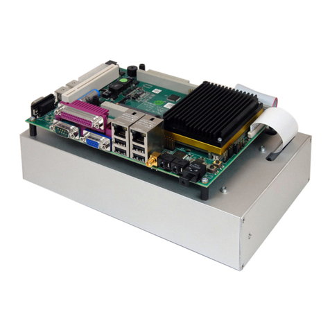
DIGITAL-LOGIC MICROSPACE PCC-P5 User manual

TECHNICAL USER'S MANUAL FOR:
SLOTCARD
PC/104 plus
PCC-P5
Nordstrasse 11/F
CH- 4542 Luterbach
Tel.: ++41 (0)32 681 58 00
Fax: ++41 (0)32 681 58 01
Email: [email protected]
Homepage: http://www.digitallogic.com

DIGITAL-LOGIC AG PCCP5 Manual V2.3
2
COPYRIGHT 1995- 2001 BY DIGITAL-LOGIC AG
No part of this document may be reproduced, transmitted, transcribed, stored in a retrieval system, in any
form or by any means, electronic, mechanical, optical, manual, or otherwise, without the prior written permis-
sion of DIGITAL-LOGIC AG.
The software described herein, together with this document, are furnished under a license agreement and
may be used or copied only in accordance with the terms of that agreement.
REVISION HISTORY:
Prod.-Serialnumber:
From: To: Product
Version Document
Version Date / by: Modification:
Remarks, News, Attention:
V1.1 V1.0 01.97 FK
V1.01 01.97 FK Different Modifications
V1.1 05.97 FK HD-PIO Modes
V1.11 07.97 FK Corrections
V2.1a V2.1 08.97 FK New Board PCC586
V2.11 08.97 FK Modified, Layout
V2.12 09.97 FK Modification DLG
V2.13 03.98 JM I/O&Memory Map corrected
V2.14 03.98 JM Detailed corrections
V2.15 05.98 JM Jumper table corrections
V2.16 06.98 JM AMIBIOS Setup description in-
cluded
V2.2 V2.20 02.99 FK Update, New Board PCC-P5
V2.21 02.99 FK VID4-VID0 Core Voltage added
V2.22 03.99 JM Thermoscan pics added
V2.23 03.99 TS Related APP-NOTES
V2.24 09.99 MAJ V2.2 designs added
V2.25 11.99 FK Jumpers mod. , AMD BFx
V2.26 01.00 STP Video in pins changed
V2.3 V2.27 04.2000 STP Jumperlist, connectors added,
minor corrections
V2.3 V2.3 03.2001 STP Few updates and corrections
Registration Form:
Please register your product under:
http://www.digitallogic.com -> SUPPORT -> Product Registration
After registration, you will receive driver & software updates, errata information, customer information and
news from DIGITAL-LOGIC AG products automatically.

DIGITAL-LOGIC AG PCCP5 Manual V2.3
3
Table of Contents
1PREFACE......................................................................................................................................................................................6
1.1 TRADEMARKS........................................................................................................................................................................6
1.2 DISCLAIMER...........................................................................................................................................................................6
1.3 WHO SHOULD USE THIS PRODUCT ......................................................................................................................................6
1.4 RECYCLING INFORMATION..................................................................................................................................................7
1.5 TECHNICAL SUPPORT ...........................................................................................................................................................7
1.6 LIMITED WARRANTY............................................................................................................................................................7
2OVERVIEW .................................................................................................................................................................................8
2.1 STANDARD FEATURES..........................................................................................................................................................8
2.2 UNIQUE FEATURES................................................................................................................................................................8
2.3 BLOCK DIAGRAM..................................................................................................................................................................9
2.4 PCC-P5 SPECIFICATIONS...................................................................................................................................................10
2.5 THERMOSCAN......................................................................................................................................................................14
2.6 ORDERING CODES...............................................................................................................................................................14
2.7 BIOS HISTORY....................................................................................................................................................................15
2.8 RELATED APPLICATION NOTES.........................................................................................................................................15
2.9 THIS PRODUCT IS “YEAR 2000 CAPABLE” ..............................................................................................15
2.10 PCC-P5L INCOMPATIBILITIES TO A STANDARD PC/AT............................................................................................15
2.11 MECHANICAL DIMENSIONS...............................................................................................................................................16
3THE ISA AND PC/104 BUS SIGNALS..............................................................................................................................17
3.1 EXPANSION BUS..................................................................................................................................................................20
4DETAILED SYSTEM DESCRIPTION..............................................................................................................................21
4.1 POWER REQUIREMENTS.....................................................................................................................................................21
4.2 CPUS, BOARDS AND RAMS..............................................................................................................................................21
4.2.1 CPUs of this MICROSPACE Product....................................................................................................................21
4.3 INTERFACES.........................................................................................................................................................................22
4.3.1 PS/2-Keyboard...........................................................................................................................................................22
4.3.2 PS/2-Mouse Interface...............................................................................................................................................22
4.3.3 Line Printer Port LPT1.............................................................................................................................................22
4.3.4 Serial Ports COM1-COM2......................................................................................................................................23
4.3.5 Floppy disk interface................................................................................................................................................24
4.3.5.1 Supported floppy formats.........................................................................................................................................24
4.3.5.2 Floppy interface connector.......................................................................................................................................24
4.3.6 Speaker interface.......................................................................................................................................................25
4.4 CONTROLLERS.....................................................................................................................................................................26
4.4.1 Interrupt Controllers................................................................................................................................................26
4.5 TIMERS AND COUNTERS.....................................................................................................................................................26
4.5.1 Programmable Timers..............................................................................................................................................26
4.5.2 Battery backed clock (RTC)....................................................................................................................................27
4.5.3 Watchdog....................................................................................................................................................................27
4.6 BIOS......................................................................................................................................................................................28
4.6.1 ROM-BIOS Sockets...................................................................................................................................................28
4.6.1.1 Standard BIOS FLASH 29F010...............................................................................................................................28
4.6.1.2 VGA BIOS FLASH 29F010....................................................................................................................................28
4.6.2 EEPROM Memory for Setup...................................................................................................................................29
4.6.3 CMOS RAM Map.......................................................................................................................................................30
4.6.4 BIOS CMOS Setup....................................................................................................................................................36
4.6.5 CMOS Setup Harddisk list.......................................................................................................................................37
4.6.6 Harddisk PIO Modes................................................................................................................................................37
4.6.7 EEPROM saved CMOS setup..................................................................................................................................38
4.7 DOWNLOAD THE VGA-BIOS AND THE CORE-BIOS..................................................................................................39
4.7.1 VGA- BIOS Download Function............................................................................................................................40
4.8 MEMORY ..............................................................................................................................................................................41
4.8.1 Onboard DRAM Memory.........................................................................................................................................41
4.8.2 System Memory Map.................................................................................................................................................41

DIGITAL-LOGIC AG PCCP5 Manual V2.3
4
4.8.3 System I/O Map..........................................................................................................................................................42
4.9 BIOS DATA AREA DEFINITIONS.......................................................................................................................................57
4.9.1.1 Compatibility Service Table.....................................................................................................................................63
4.10 VGA, LCD...........................................................................................................................................................................64
4.10.1 VGA / LCD Controller C&T65554 and C&T65555...........................................................................................64
4.10.2 VGA / LCD BIOS for 65555 and(69000 not supported) ..................................................................................65
4.10.3 Memory 65554/65555/CRT/TFT Panels...............................................................................................................66
4.10.4 Memory 65554/65555 Color STN-DD Panels....................................................................................................67
4.10.5 Memory 65554/65555 Mono STN-DD Panels.....................................................................................................68
4.10.6 Supported Standard VGA Modes..........................................................................................................................69
4.10.7 VGA CRT/LCD Display Driver...............................................................................................................................70
4.10.7.1 65554/65555 HiQV64 VGA Driver Resolutions.................................................................................................71
4.10.8 Video Input Board V2.1a and older with the VPX3220....................................................................................71
4.11 HIQ VIDEO MULTIMEDIA SUPPORT ..............................................................................................................................72
4.11.1 HiQVideo Series Programming Examples..........................................................................................................73
4.11.1.1 Introduction.........................................................................................................................................................73
4.11.1.2 Video Playback through PCI/VL Bus..................................................................................................................73
4.11.1.3 Video Capture and Playback Through Video Port ..............................................................................................73
4.11.1.4 ZoomUp...............................................................................................................................................................73
4.11.1.5 Video Capture Using the Video Port...................................................................................................................73
4.11.2 How to enable video capture and playback module (Init) .................................................................................74
4.11.3 How to disable video playback and capture module (Exit) ...............................................................................75
4.11.4 How to start video capture......................................................................................................................................75
4.11.5 How to stop video capture.......................................................................................................................................76
4.11.6 How to set input video color format.......................................................................................................................77
4.11.7 How to set interlaced or non-interlaced video input..........................................................................................77
4.11.8 How to enable/disable double buffer......................................................................................................................78
4.11.9 How to scale input video (before acquiring into frame buffer) .........................................................................78
4.11.10 How to crop input video (programming of acquisition rectangle)...............................................................79
4.11.11 Video Input boardV2.2 and newer with the SAA7111 VIP........................................................................84
4.11.11.1 Features of the SAA7111A VideoInput Processor..............................................................................................84
4.11.11.2 Operation of the SAA7111A VideoInput Processor...........................................................................................85
5DESCRIPTION OF THE CONNECTORS.......................................................................................................................86
5.1 JUMPERS ON THIS MICROSPACE PRODUCT .................................................................................................................99
5.1.1 CPU core voltages selection, (since V2.2) .....................................................................................................101
5.2 JUMPERAND CONNECTOR LOCATIONS..........................................................................................................................103
PCC-P5 V2.1.............................................................................................................................................................................103
5.2.2 PCC-P5 V2.2...........................................................................................................................................................105
5.2.3 PCC-P5 V2.3...........................................................................................................................................................107
6LED CRITERIONS:.............................................................................................................................................................109
7CABLE INTERFACE...........................................................................................................................................................109
7.1 THE FLOPPY DISK CABLE................................................................................................................................................109
7.2 THE HARDDISK CABLE 40 PINS.......................................................................................................................................110
7.3 THE HARDDISK CABLE 44 PINS.......................................................................................................................................111
7.4 THE COM 1/2 SERIAL INTERFACE CABLE....................................................................................................................112
8SPECIAL PERIPHERALS, OPTIONAL FUNCTIONS............................................................................................113
8.1 SPECIAL PERIPHERALS.....................................................................................................................................................113
8.1.1 Multifunction latch.................................................................................................................................................113
9ETHERNET LAN..................................................................................................................................................................114
9.1 ETHERNET IO-ADDRESS AND IRQ SELECTION.............................................................................................................114
9.2 ETHERNET HARDWARE CONFIGURATION.......................................................................................................................115
9.3 UTILITIES FOR PROGRAMMING EEPROM AND DIAGNOSTICS..............................................................................116
9.4 ETHERNET-DRIVERS.........................................................................................................................................................116
9.4.1 INT 15h SFR Functions.........................................................................................................................................117
10 SCSI INTERFACE (OPTION)......................................................................................................................................123
10.1 SCSI DRIVERS FOR OPERATING SYSTEM SUPPORT ......................................................................................................124

DIGITAL-LOGIC AG PCCP5 Manual V2.3
5
11 SOUNDPORT DRIVER INSTALLATION.............................................................................................................125
11.1 DOS DRIVER......................................................................................................................................................................125
11.2 WIN311, OS2, WIN95, WIN98, WIN NT...................................................................................................................126
11.3 AD1816 SOUND CHIP .......................................................................................................................................................127
11.3.1 Driver for WIN 3.11...............................................................................................................................................127
11.3.2 Driver for WIN 95..................................................................................................................................................128
11.3.3 Driver for NT4.0 .....................................................................................................................................................128
11.3.4 Bundled Applications, MediaRack ......................................................................................................................128
12 INSTALLING THE FLASHDISK DOC2000...........................................................................................................129
12.1 ENABLING AND FORMATTING OF THE DISKONCHIP-MODULES................................................................................129
13 BUILDING A SYSTEM...................................................................................................................................................130
13.1 STARTING UP THE SYSTEM ..............................................................................................................................................130
13.2 ERROR ON BOOT TIME......................................................................................................................................................132
14 DIAGNOSTICS..................................................................................................................................................................133
15 AMIBIOS®HIFLEX SETUP DESCRIPTION.........................................................................................................136
15.1 ENTERING BIOS SETUP ...................................................................................................................................................136
15.2 STANDARD CMOS SETUP ...............................................................................................................................................138
15.3 ADVANCED CMOS SETUP ..............................................................................................................................................139
15.3.1 A short description of this screen's items follows:............................................................................................139
15.4 ADVANCED CHIPSET SETUP ............................................................................................................................................141
15.4.1 A Short description of the screen's items follows:............................................................................................141
15.5 POWERMANAGEMENT SETUP ........................................................................................................................................142
15.5.1 A short description of this screen's items follows:............................................................................................142
15.6 PCI / PLUG AND PLAY SETUP .........................................................................................................................................144
15.6.1 A short description of this screen's items follows:............................................................................................144
15.7 PERIPHERAL SETUP...........................................................................................................................................................146
15.7.1 A short description of this screen's items follows:............................................................................................146
16 INDEX...................................................................................................................................................................................147

DIGITAL-LOGIC AG PCCP5 Manual V2.3
6
1PREFACE
This manual is for integrators and programmers of systems based on the MICROSPACE card family. It con-
tains information on hardware requirements, interconnections, and details of how to program the system.
The specifications given in this manual were correct at the time of printing; advances mean that some may
have changed in the meantime. If errors are found, please notify DIGITAL-LOGIC AG at the address shown
on the title page of this document, and we will correct them as soon as possible.
1.1 Trademarks
MICROSPACE, MicroModule DIGITAL-LOGIC AG
DOS Vx.y, Windows Microsoft Inc.
PC-AT, PC-XT IBM
NetWare Novell Corporation
Ethernet Xerox Corporation
DR-DOS, PALMDOS Digital Research Inc. / Novell Inc.
ROM-DOS Datalight Inc.
1.2 Disclaimer
DIGITAL-LOGIC AG makes no representations or warranties with respect to the contents of this manual and
specifically disclaims any implied warranty of merchantability or fitness for any particular purpose. DIGITAL-
LOGIC AG shall under no circumstances be liable for incidental or consequential damages or related ex-
penses resulting from the use of this product, even if it has been notified of the possibility of such damage.
DIGITAL-LOGIC AG reserves the right to revise this publication from time to time without obligation to notify
any person of such revisions. If errors are found, please contact DIGITAL-LOGIC AG at the address listed on
the title page of this document.
1.3 Who should use this Product
-Electronic engineers with know-how in PC-technology.
-Without electronic know-how we expect you to have questions. This manual assumes, that you have a
general knowledge of PC-electronics.
-Because of the complexity and the variability of PC-technology, we can’t give any warranty that the prod-
uct will work in any particular situation or combination. Our technical support will help you to may get a
solution.
-Pay attention to the electrostatic discharges. Use a CMOS protected workplace.
-Power supply OFF when you are working on the board or connecting any cables or devices.
This is a high-technology product.
You need know-how in electronics and PC-technology to
install the system !

DIGITAL-LOGIC AG PCCP5 Manual V2.3
7
1.4 Recycling Information
Hardware: - Print: epoxy with glass fiber
wires are of tin-plated copper
- Components: ceramics and alloys of gold, silver
check your local electronic recycling
Software: - no problems: re-use the diskette after formatting
1.5 Technical Support
1. Contact your local DIGITAL-LOGIC Technical Support in your country first !
2. Use the Internet Support Request form at http://www.digitallogic.com -> Support -> Support Request
Form
3. Send a FAX or an E-mail to DIGITAL-LOGIC AG with a description of your problem.
DIGITAL-LOGIC AG
smartModule DesignIn Center
Nordstr. 11/F
CH-4542 Luterbach (SWITZERLAND)
Fax: ++41 32 681 58 01
E-Mail: [email protected]
Internet www.digitallogic.com
èSupport requests will only be accepted with detailed information of the product (BIOS-, Board- Version) !
1.6 Limited Warranty
DIGITAL-LOGIC AG warrants the hardware and software products it manufactures and produces to be free
from defects in materials and workmanship for one year following the date of shipment from DIGITAL-LOGIC
AG, Switzerland. This warranty is limited to the original purchaser of product and is not transferable.
During the one year warranty period, DIGITAL-LOGIC AG will repair or replace, at its discretion, any defec-
tive product or part at no additional charge, provided that the product is returned, shipping prepaid, to
DIGITAL-LOGIC AG. All replaced parts and products become property of DIGITAL-LOGIC AG.
Before returning any product for repair, customers are required to contact the company.
This limited warranty does not extend to any product which has been damaged as a result of accident, mis-
use, abuse (such as use of incorrect input voltages, wrong cabling, wrong polarity, improper or insufficient
ventilation, failure to follow the operating instructions that are provided by DIGITAL-LOGIC AG or other con-
tingencies beyond the control of DIGITAL-LOGIC AG), wrong connection, wrong information or as a result of
service or modification by anyone other than DIGITAL-LOGIC AG. Neither if the user has not enough knowl-
edge of these technologies or has not consulted the product manual or the technical support of DIGITAL-
LOGIC AG and therefore the product has been damaged.
Except, as expressly set forth above, no other warranties are expressed or implied, including, but not limited
to, any implied warranty of merchantability and fitness for a particular purpose, and DIGITAL-LOGIC AG ex-
pressly disclaims all warranties not stated herein. Under no circumstances will DIGITAL-LOGIC AG be liable
to the purchaser or any user for any damage, including any incidental or consequential damage, expenses,
lost profits, lost savings, or other damages arising out of the use or inability to use the product.

DIGITAL-LOGIC AG PCCP5 Manual V2.3
8
2OVERVIEW
2.1 Standard Features
The MICROSPACE PC is a miniaturized modular device incorporating the major elements of a PC/AT com-
patible computer. It includes standard PC/AT compatible elements, such as:
-Powerful PENTIUM CPU 100 MHz up to 200 MHz,
Supports optional 2.9V CPU’s like INTEL-MMX, AMD and CYRIX
-FLASH BIOS , downloadable
-DRAM 4 - 128 MByte
-256k burst piplined second level cache
-Timers
-DMA
-Real-time clock with CMOS-RAM and battery buffer
-LPT1 parallel port
-COM1, COM2 serial port
-PS/2 keyboard interface
-PS/2 mouse Interface
-SVGA/LC Display interface
-Floppy disk Interface
-E-IDE harddisk interface
-ISA-Bus
-Optional SCSI-2 with 10MB/s
-Optional Ethernet-LAN, 10 Base-2
-Optional Video Input for 3 sources, PAL/NTSC
-Optional Soundport
2.2 Unique Features
The MICROSPACE PCC-P5 includes all standard PC/AT functions plus unique DIGITAL-LOGIC AG en-
hancements, such as:
-Low-power consumption, 17 watt
-Single 5 volt supply
-Watchdog
-Power-fail circuit
-EEPROM setup and configuration
-Video Input for 3 video sources PAL or NTSC
-DiskOnChip Flashdisk up to 72MByte
-PC/104+ PCI extension
-UL approved parts

2.3 Block Diagram
Ethernet LAN
SMC 91C94/96
P5-166MHz
CPU
CACHE
256 kByte TXC
HX DRAM
4 - 128 MByte
3,3V
2,9V switched
PIIX3
EIDE LCD/VGA
Controller 65554/65555
VideoRAM
1, 2 MByte
opt. 4 MByte
SCSI Controller
NCR53C810
SCSI
PCI-BUS
Speaker
LCD CRT DA
Video-Input
ISA-BUS
PC/104 KB Mouse
EEPROM
2kByte
Soundport
AD1816
ESS1816 (V2.2)
RTC
Watchdog
Temp.
Sensor
10Base-2
LiBAT
ISA-BUS
HOST BUS
Super I/O
37C666
MAX2ll
X
FD LPT1
MAX2ll
COM1 COM2
IDE
KB Mouse
10Base-T
L R
Speaker MIC
PCI-BUS
PC/104-Plus
BIOS
128kByte
ADM
489 ADM
489
USB
(Notsup-
ported)
Watchdog

DIGITAL-LOGIC AG PCCP5 Manual V2.3
10
2.4 PCC-P5 Specifications
CPU:
CPU 64 Bit: Pentium 100MHz up to 200MHz
CPU 16 Bit: None
Mode: Real / Protected
Compatibility: 8086 – 80486
Word Size: 32 Bits
Physical Addressing: 32 lines
Virtual Addressing: 16 Gbytes
Clock Rates: 100 / 133 / 166 / 200 MHz
Socket Standard: Socket 7 with 324 pins, 3.3V switched, (Option: 2,9V sw/ 3.3V lin)
Since V2.2: free programmable CPU-Voltage 1.6V to 3.5V
2nd. Level Cache:
available 256k onboard, burst pipelined SRAM for max. performance
PC-Chipset:
Intel HX430 (TRITON)
DMA:
8237A comp. 4 channels 8 Bits
3 channels 16 Bits
Interrupts:
8259 comp. 8 + 7 levels, PC compatible
Timers:
8254 comp. 3 programmable counter/timers
Memory:
DRAM 2 x 72 pin SIMM, 60ns, 4,16, 32, 64, 128MByte
Video Output:
Controller: 65554 / 65555 from C&T
BUS: 32 Bit highspeed 33 MHz PCI bus
Enhanced BIOS: Multi VGA / LCD BIOS
Video-Memory: 2 MByte - 32 bit, expandable up to 4MByte
CRT-Monitor: up to 1600 x 1280 pixels
Flatpanel: TFT: 640 x 480, 800 x 600, 1024 x 768
STN: 640 x 480 color and monochrome
Plasma: up to 1280 x 1024
EL: 640 x 350, 640 x 480
Flatpanelinterface: Standard: 65554/65555 = TTL
Optional: 68554 = C&T PanelLink
Controller Modes: CRT only; Flatpanel only or simultaneous CRT and Flatpanel
Drivers: Windows 3.11, WIN95, NT3.5, NT4.0 and other applications

DIGITAL-LOGIC AG PCCP5 Manual V2.3
11
Video Input: (option)
Controller: 65554 / 65555 from C&T
BUS: 32 Bit highspeed 33 MHz PCI bus
Videoinput Norm: 3 channels with PAL or NTSC (composite video sources = CVBS)
2 channels YC sources (=SVHS)
2 channels CVBS and 1 channel SVHS
V2.1A: may be programmed into the ITT VPX 3220A
Since V2.2: Philips SAA7111
Driversupport: DOS, WIN95 (demosoftware)
Resolution: 320 x 240 with 65554 / 69000
optional: 568 x 720 with 65555 or 69000
Capture speed: up to 30 images/second
PAL/NTSC Decoder: until V2.1A ITT VPX 3220A
since V2.2: Philips SAA7111A
Y-C resolution: 4:4:4 or 4:2:2 or 4:1:1
RGB resolution: 4:4:4 (16 Bit), gamma corrected
Mass Storage:
FD: Floppy disk interface, for max. 2 floppies, 34pin connector
HD: E-IDE interface, 40pin interface up to 12MByte fast IDE transferrates
SCSI Devices: PCI 10MB/s FAST SCSI-2 up to 7 devices, removable boot media
NCR 53C810 PCI SCSI controller
Standard AT interfaces:
Serial: Name FIFO IRQs Addr. Standard Option
COM1
COM2 yes
yes IRQ4
IRQ3 3F8
2F8 RS232C
RS232C RS422/RS485
RS422/RS485
(Baudrates: up to 115kBaud), RS485 is an assembling option
Parallel: LPT1 printer interface, in the EPP Mode bidirectional
Keyboard: PS/2
Mouse: PS/2
Speaker: 0.1W output drive
RTC: 146818A compatible RTC with CMOS-RAM 128Byte
Backup current: < 5µA
Battery: Lithium 3V (48mAh)
LAN - Ethernet: (option)
Type: IEEE 802.3
Controller: SMC 91C94 / 96
Compatibility: ODI-Novell
Driver: ODI, packet-driver IEEE 802.3, NT3.5, OS/2, NDIS, NT4.0
Connector: 10Base-T (optionally assembled)
10Base-2 (standard assembled)
Data Rate: 10 MB/sec
Data-Bus: 16 Bit
Cable Type: RG/58A/U 50 ohms
Remote Boot Socket: none
RAM Buffer: 4k
Configuration: with EEPROM

DIGITAL-LOGIC AG PCCP5 Manual V2.3
12
Sound I/O: (option)
Controller: Until V2.1A: AD1816 8Bit Soundblaster compatible
Since V2.2: ESS1869 8Bit Soundblaster compatible, with LM1877
Driver Support: DOS, WIN 3.11, WIN95, NT4
Output channels: Stereo Output Line Level
Input: Microphone, Line
Features: - Compatible with: SoundBlasterPro 8 Bit, AD-Lib,
MicroSoft-Windows Sound System
- OPL3 Synthesizer built in
- 3D Stereo Enhancement
- Digital mixer
- Game Port, Midi Interface
- Programmable IRQs, DRQs and I/O addresses
- Supports 16 Bit type F DMA playback
Supervisory:
Watchdog: LTC1232 with power-fail detection
USB external:
Controller: 430HX / PIIX3
Transferrate: 12.5MBps / 1.5 MBps
BUS internal:
PCI IEEE-996 standard bus, by Intel
Clock: 33MHz with 32bit data path and 100MB/s transferrate
BUS external:
ISA IEEE-996 standard bus
Clock: 8 MHz or programmable
Embedded BUS:
PC/104 IEEE-996 standard bus
Clock: 8 MHz or programmable
PC/104+ PCI 32bit, 33Mhz bus, this is an assembling option
Power Supply:
Working: 5 Volts ±5%
Current: 3.4A nominal, using P5-166 MHz
Suspend: 2.5A
Rise Time: >100µs from 0V to 4.75V

DIGITAL-LOGIC AG PCCP5 Manual V2.3
13
Physical Characteristics:
Dimensions: Length: 200 mm / 7.9"
Depth: 120 mm / 4,7"
Height: 50 mm / 1.95"
Weight: 360 gr
PCB Thickness: 1.6 mm / 0.0625 inches nominal
PCB Layer: Multilayer
Operating Environment:
Relative humidity: 5 - 90% non condensing
Vibration: 5 to 2000 Hz
Shock: 10 G
Temperature: Operating: Standard version: -25°C to +60°C
Enhanced temp. range: -25°C to +70°C -E27
Storage: -55°C to +85°C
Cooling:
Standard: 5V Fan, with feedback (frequency sensor)
Temperaturesensor: onboard, located in the center below the CPU
Option: passive with air flow > 1000ft/Min.
EMI / EMC (IEC1131-2 refer MIL 461/462):
ESD Electro Static Discharge: IEC 801-2, EN55101-2, VDE 0843/0847 Part 2
metallic protection needed, separate Ground Layer
included,15kV single peak
REF Radiated Electromagnetic Field: IEC 801-3, VDE 0843 Part 3, IEC770 6.2.9.
not tested
EFT Electric Fast Transient (Burst): IEC 801-4, EN50082-1, VDE 0843 Part 4
250V - 4kV, 50 ohms, Ts=5ns
Grade 2: 1KV Supply, 500 I/O, 5Khz
SIR Surge Immunity Requirements:IEC 801-5, IEEE587, VDE 0843 Part 5
Supply: 2 kV, 6 pulse/minute
I/O: 500 V, 2 pulse/minute
High-Frequency Radiation:EN55022
Compatibility:
PCCP5: mechanically compatible to standard ISA slot cards
Any information is subject to change without notice.

DIGITAL-LOGIC AG PCCP5 Manual V2.3
14
2.5 Thermoscan
Product: PCCP5 Scan time: 120min.
2.6 Ordering Codes
PCCP5 MICROSPACE PCCard without CPU, with 256k Cache
no Options
Standard Board:
PCCP5-E2SA MICROSPACE PCCard without CPU, with 256k Cache
with SCSI, with Sound, with Ethernet
Option - E2 Ethernet LAN 10 Base-2 (BNC )
Option - E1 Ethernet LAN 10 Base-T (twisted pair)
Option - S SCSI-2
Option - A Audio Sound Interface
Option -V4M 4MB Video RAM Option
Option P+ PC/104+ PCI Bus
Option -VINP Video Input 3 channels
Option -R2 RS485 option on the COM2 instead of the RS232C
Option 2.9V/3.3V OEM production, depending of the used CPU
Option 44pin IDE OEM production
Option 26pin FDC OEM production

DIGITAL-LOGIC AG PCCP5 Manual V2.3
15
2.7 BIOS History
Version: Date: Status: Modifications:
V3.20 Aug.98. released Y2K tested
V3.21 Nov.98 beta new version for MSM-P5 V4.0
V3.24 Jun.99 released Port and setup options
2.8 Related Application Notes
#Description
64 Bestückungsrichtlinien PCCP5
74 HX-Power Management of DLAG products
77 Ethernet EEPROM values do not match
80 High frequency Radiation (to meet EN55022)
84 Power consumption on Pentium / any other boards with at-
tached drives (HDD, CD)
85 LAN TABLE update MSMP5S
èApplication Notes are available at http://www.digitallogic.com ->support, or on any Application CD from
DIGITAL-LOGIC.
2.9 This product is “YEAR 2000 CAPABLE”
This DIGITAL-LOGIC product is “YEAR 2000 CAPABLE”. This means, that upon installation, it accurately
stores, displays, processes, provides and/or receives date data from, into, and between 1999 and 2000, and
the 20. and 21. centuries, including leap year calculations, provided that all other technology used in combi-
nation with said product properly exchanges date data with it. DIGITAL-LOGIC makes no representation
about individual components within the product should be used independently from the product as a whole.
You should understand that DIGITAL-LOGIC’s statement that an DIGITAL-LOGIC product is “YEAR 2000
CAPABLE” means only that DIGITAL-LOGIC has verified that the product as a whole meet this definition
when tested as a stand-alone product in a test lab, but dies not mean that DIGITAL-LOGIC has verified that
the product is “YEAR 2000 CAPABLE” as used in your particular situation or configuration. DIGITAL-LOGIC
makes no representation about individual components, including software, within the product should they be
used independently from the product as a whole.
DIGITAL-LOGIC customers use DIGITAL-LOGIC products in countless different configurations and in con-
junction with many other components ans systems, and DIGITAL-LOGIC has no way to test wheter all those
configurations and systems will properly handle the transition to the year 2000. DIGITAL-LOGIC encourages
its customers and others to test whether their own computer systems and products will properly handle the
transition to the year 2000.
The only proper method of accessing the date in systems is indirectly from the Real-Time-Clock via the
BIOS. The BIOS in DIGITAL-LOGIC computerboards contain a century checking and maintenance feature
the checks the laest two significant digits of the year stored in the RTC during each BIOS request (INT 1A) to
read the date and, if less than ‘80’ (i.e. 1980 is the first year supported by the PC), updates the century byte
to ‘20’. This feature enables operating systems and applications using BIOS date/time services to reliably
manipulate the year as a four-digit value.
2.10 PCC-P5L Incompatibilities to a standard PC/AT
No incompatibilities are observed.

DIGITAL-LOGIC AG PCCP5 Manual V2.3
16
2.11 Mechanical Dimensions
11 14.6 30.8 23.6 15.4
1.4
238022.5
27.5
47
11.6
36.4
49.39.710.12.9
11 16 72.9 74.9 20.2
120
200
105.4
2.9
8.6
22.8
7.6
40.8
46
54
50.3
12.6
29.6
45.6
54.6
47.1 67.3 78.8
7.6
9.2
12.1
5.6
PCC586 V2.1, 06/97
All Dimensions are in millimeters, +/- 0.1
U4 CPU - P5
U11 CHIPSET
HX - BGA
U7 -6555x
VGA - BGA
U8
VGA
BIOS U85
U29
BIOS
6.5 5.5 9.5
7.0
J78
J80 J79
J51
J54
J52
J53
J77
J67
J62 J70 J17
J27
PC104 - NORM J34/J35J3J4
J7J8
J1
J76
J75
POWER J44
-+
J21
J37
J38
J5
J25
J23
J65 - PC104 PLUS
J31
J18
J32 J6 J22 J61
J40
3.0TYP HOLE
6.0TYP GND RING
U75
J71
J43 J41 J42
J85,J84,J83,J82
J81
2.0TYP:J5,J23,J65,J77
2.5TYP:J17,J18,J21,J25,J31,J34,J35,J38,J67

DIGITAL-LOGIC AG PCCP5 Manual V2.3
17
3THE ISA AND PC/104 BUS SIGNALS
AEN, output
Address Enable is used to degate the microprocessor and other devices from the I/O channel to allow DMA
transfers to take place. low = CPU Cycle , high = DMA Cycle
BALE, output
Address Latch Enable is provided by the bus controller and is used on the system board to latch valid ad-
dresses and memory decodes from the microprocessor. This signal is used so that devices on the bus can
latch LA17..23. The SA0..19 address lines latched internally according to this signal. BALE is forced high
during DMA cycles.
/DACK[0..3, 5..7], output
DMA Acknowledge 0 to 3 and 5 to 7 are used to acknowledge DMA requests (DRQO through DRQ7). They
are active low. This signal indicates that DMA operation can begin.
DRQ[0..3, 5..7], input
DMA Requests 0 through 3 and 5 through 7 are asynchronous channel requests used by peripheral devices
and the I/O channel microprocessors to gain DMA service (or control of the system). A request is generated
by bringing a DRQ line to an active level. A DRQ line must be held high until the corresponding DMA Re-
quest Acknowledge (DACK/) line goes active. DRQO through DRQ3 will perform 8-bit DMA transfers; DRQ5-
7 are used for 16 accesses.
/IOCHCK, input
IOCHCK/ provides the system board with parity (error) information about memory or devices on the I/O
channel. low = parity error , high = normal operation
IOCHRDY, input
I/O Channel Ready is pulled low (not ready) by a memory or I/O device to lengthen I/O or memory cycles.
Any slow device using this line should drive it low immediately upon detecting its valid address and a Read
or Write command. Machine cycles are extended by an integral number of one clock cycle (67 nanosec-
onds). This signal should be held low for no more than 2.5 microseconds. low = wait, high = normal opera-
tion
/IOCS16, input
I/O 16 bit Chip Select signals the system board that the present data transfer is a 16-bit, 1 wait-state, I/0 cy-
cle. It is derived from an address decode. /IOCS16 is active low and should be driven with an open collector
(300 ohm pull-up) or tri-state driver capable of sinking 20mA. The signal is driven based only on SA15-SAO
(not /IOR or /IOW) when AEN is not asserted. In the 8 bit I/O transfer, the default transfers a 4 wait-state cy-
cle.
/IOR, input/output
I/O Read instructs an I/O device to drive its data onto the data bus. It may be driven by the system micro-
processor or DMA controller, or by a microprocessor or DMA controller resident on the I/O channel. This sig-
nal is active low.
/IOW, input/output
I/O Write instructs an I/O device to read the data on the data bus. It may be driven by any microprocessor or
DMA controller in the system. This signal is active low.

DIGITAL-LOGIC AG PCCP5 Manual V2.3
18
IRQ[ 3 - 7, 9 - 12, 14, 15], input
These signals are used to tell the microprocessor that an I/O device needs attention. An interrupt request is
generated when an IRQ line is raised from low to high. The line must be held high until the microprocessor
acknowledges the interrupt request .
/Master, input
This signal is used with a DRQ line to gain control of the system. A processor or DMA controller on the I/0
channel may issue a DRQ to a DMA channel in cascade mode and receive a /DACK.
/MEMCS16, input
MEMCS16 Chip Select signals the system board if the present data transfer is a 1 wait-state, 16-bit, memory
cycle. It must be derived from the decode of LA17 through LA23. /MEMCS16 should be driven with an open
collector (300 ohm pull-up) or tri-state driver capable of sinking 2OmA.
/MEMR input/output
These signals instruct the memory devices to drive data onto the data bus. /MEMR is active on all memory
read cycles. /MEMR may be driven by any microprocessor or DMA controller in the system. When a micro-
processor on the I/0 channel wishes to drive /MEMR, it must have the address lines valid on the bus for one
system clock period before driving /MEMR active. These signals are active low.
/MEMW, input/output
These signals instruct the memory devices to store the data present on the data bus. /MEMW is active in all
memory read cycles. /MEMW may be driven by any microprocessor or DMA controller in the system. When a
microprocessor on the I/O channel wishes to drive /MEMW, it must have the address lines valid on the bus
for one system clock period before driving /MEMW active. Both signals are active low.
OSC, output
Oscillator (OSC) is a high-speed clock with a 70 nanosecond period (14.31818 MHz). This signal is not syn-
chronous with the system clock. It has a 50% duty cycle. OSC starts 100us after reset is inactive.
RESETDRV, output
Reset Drive is used to reset or initiate system logic at power-up time or during a low line-voltage outage. This
signal is active high. When the signal is active all adapters should turn off or tri-state all drivers connected to
the I/O channel. This signal is driven by the permanent Master.
/REFRESH, input/output
These signals are used to indicate a refresh cycle and can be driven by a microprocessor on the I/0 channel.
These signals are active low.
SAO-SA19, LA17 - LA23 input/output
Address bits 0 through 19 are used to address memory and I/0 devices within the system. These 20 address
lines, allow access of up to 1MBytes of memory. SAO through SA19 are gated on the system bus when
BALE is high and are latched on the falling edge of BALE. LA17 to LA23 are not latched and addresses the
full 16 MBytes range. These signals are generated by the microprocessors or DMA controllers. They may
also be driven by other microprocessor or DMA controllers that reside on the I/0 channel. The SA17-SA23
are always LA17-LA23 address timings for use with the MSCS16 signal. This is advanced AT96 design. The
timing is selectable with jumpers LAxx or SAxx.
/SBHE, input/output
Bus High Enable (system) indicates a transfer of data on the upper byte of the data bus, SD8 through SD15.
Sixteen-bit devices use /SBHE to condition data-bus buffers tied to SD8 through SD15.

DIGITAL-LOGIC AG PCCP5 Manual V2.3
19
SD[O..15], input/output
These signals provide bus bits 0 through 15 for the microprocessor, memory, and I/0 devices. DO is the
least-significant bit and D15 is the most significant bit. All 8-bit devices on the I/O channel should use DO
through D7 for communications to the microprocessor. The 16-bit devices will use DO through D15. To sup-
port 8-bit device, the data on D8 through D15 will be gated to DO through D7 during 8-bit transfers to these
devices; 16-bit microprocessor transfers to 8-bit devices will be converted to two 8-bit transfers.
/SMEMR input/output
These signals instruct the memory devices to drive data onto the data bus for the first MByte. /SMEMR is
active on all memory read cycles. /SMEMR may be driven by any microprocessor or DMA controller in the
system. When a microprocessor on the I/0 channel wishes to drive /SMEMR, it must have the address lines
valid on the bus for one system clock period before driving /SMEMR active. The signal is active low.
/SMEMW, input/output
These signals instruct the memory devices to store the data present on the data bus for the first MByte.
/SMEMW is active in all memory read cycles. /SMEMW may be driven by any microprocessor or DMA con-
troller in the system. When a microprocessor on the I/O channel wishes to drive /SMEMW, it must have the
address lines valid on the bus for one system clock period before driving /SMEMW active. Both signals are
active low.
SYSCLK, output
This is a 8 MHz system clock. It is a synchronous microprocessor cycle clock with a cycle time of 167 nano-
seconds. The clock has a 50% duty cycle. This signal should only be used for synchronization. It is not in-
tended for uses requiring a fixed frequency.
TC output
Terminal Count provides a pulse when the terminal count for any DMA channel is reached. The TC com-
pletes a DMA-Transfer. This signal is expected by the onboard floppy disk controller.
/OWS, input
The Zero Wait State (/OWS) signal tells the microprocessor that it can complete the present bus cycle with-
out inserting any additional wait cycles. In order to run a memory cycle to a 16-bit device without wait cycles,
/OWS is derived from an address decode gated with a Read or Write command. In order to run a memory
cycle to an 8-bit device with a minimum of one-wait states, /OWS should be driven active one system clock
after the Read or Write command is active, gated with the address decode for the device. Memory Read and
Write commands to an 8-bit device are active on the falling edge of the system clock. /OWS is active low
and should be driven with an open collector or tri-state driver capable of sinking 2OmA.
12V +/- 5%
used only for the flatpanel backligth supply only.
GROUND = 0 Volt
used for the entire system.
VCC, +5V +/- 0.25 Volt
3-4 Amp. nominal, peak current of HD, SCSI-Devices and Cache could go up to 8 Amp..

DIGITAL-LOGIC AG PCCP5 Manual V2.3
20
3.1 Expansion Bus
The bus currents are:
Output-Signals: IOH: IOL:
D0 - D16 24mA 24mA
A0 - A23: 24mA 24mA
MR,MW,IOR,IOW,
RES,ALE,AEN,C14 24mA 24mA
DACKx, DRQx,INTx,
PSx, OPW 24mA 24mA
Input-Signals: Logic-Family: Voltage:
ABT-Logic ABT-Logic
Input Signals: ViH(min.) = 2.15V ViL(max.) = 0.85V
Table of contents
Other DIGITAL-LOGIC Microcontroller manuals
Popular Microcontroller manuals by other brands

Cypress Semiconductor
Cypress Semiconductor GX3 EEPROM Programming & user guide

Efinix
Efinix Titanium user guide

TENX TECHNOLOGY
TENX TECHNOLOGY 82314BW user manual

Atmel
Atmel AVR32 STK1000 quick start guide

Geehy SEMICONDUCTOR
Geehy SEMICONDUCTOR APM32F405/415 G Series user manual

Texas Instruments
Texas Instruments CC2510 Quick start instructions

Toshiba
Toshiba TC9349AFG manual

Xilinx
Xilinx MIcroBlaze Development Spartan-3E 1600E Kit Getting started

PLX Technology
PLX Technology PEX 8509RDK Hardware reference manual

Texas Instruments
Texas Instruments TPS65941120-Q1 user guide

bendlabs
bendlabs Two Axis Getting started guide

Texas Instruments
Texas Instruments MSP432P401R user guide