Digital Sputnik DS 1 User manual
DS1 User Manual
June 2019
2
DS1 User Manual
Table of Content
Safety instructions 3
Intended use 4
1. HARDWARE 5
Parts list: DS1 Advanced System / DS1 System 5
DS1 System Specifications 6
Hardware and Firmware Versions 7
What's included 8
PSU interface 10
Module setup 12
2.CONTROL 14
Color page 14
Color control 14
Setup Page 18
DS mode ON/DS ADDR 20
DS mode OFF/DS ADDR 21
Various DMX personalities 22
WiFi page 23
Upgrade 27
Bootloader Mode 27
Warning codes (flashing codes) 28
Error codes 29

3
DS1 User Manual
Safety instructions
1. Please read through these instructions carefully before operating the DS LED
Lighting System, and keep these instructions for future reference.
2. There are numerous safety instructions and warnings that must be followed for
your own safety.
3. DS LED Lighting Systems are not intended for residential use. They are intended for
use in a professional studio or film set.
4. Maintenance must be carried out exclusively by an authorized technician.
5. The Systems are not for use in hazardous locations.
6. Maximum ambient temperature for use is 55°C / 131°F.
6.1 Do not cover cooling slots and/or radiator fins.
6.2 Keep a clear area of 25 cm (10”) from the lit face of the module.
7. The beam intensity is high. Never look directly into the light source.
8. Do not lift or suspend Light module or Power Supply Unit (PSU) by the cables.
9. Do not use any module or cable that has visible damage.
10. Connect the DS PSU unit only to a well grounded power source.
11. Avoid contact with the LED elements, pressure on the lens may damage the LED
element.
12. Connecting any equipment from other manufacturers to the DS LED Lighting
System can damage both the DS system and said equipment. Any such use will void
warranty. Use the DS light modules only with a DS PSU.
13. The System is rated for indoor use only.
Safety instructions

4
DS1 User Manual
Intended use
This product has been designed as a professional illumination tool for dry environments.
Please always follow the safety instructions.
Any usage other than described in this manual is not advised and can damage the
product and lead to risks such as fire, electric shock, etc. You are not allowed to modify
the product.
Intended use

5
DS1 User Manual
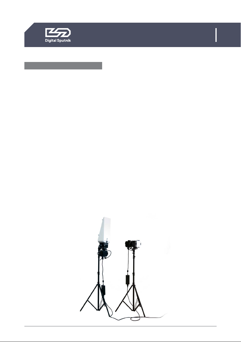
1. HARDWARE / DS1 /Ds1 Dual System
DS1 Dual System
1 Pcs – DS1 Dual Cardboard Box
2 Pcs – DS1 PSU
2 Pcs – DS1 AC/DC Converter
2 Pcs – DS Light Module RGBW
2 Pcs – DS Tripod Mount
4 Pcs – DS Eccentric Lock
2 Pcs – DS Light Module Cable
2ft/0.75m
2 Pcs – DS1 XLR Y-Cable
2 Pcs – 1x1 Diffuser Lens 34/76
with bag
12 Pcs – Clip
1 Pcs – Clip Bag
1 Pcs – AC Cable IECLock C13 6ft US/EU
2 Pcs – DS1 Module SoftBlade
1 Pcs – DS1 Quick Start Guide
1 Pcs – Softblade Quick Start Guide
DS1 System
1 Pcs – DS1 Cardboard Box
1 Pcs – DS1 PSU
1 Pcs – DS1 AC/DC Converter
1 Pcs – DS Light Module RGBW
1 Pcs – DS Tripod Mount
2 Pcs – DS Eccentric Lock
1 Pcs – DS Light Module Cable 2ft/0.75m
1 Pcs – DS1 XLR Y-Cable
1 Pcs – 1x1 Diffuser Lens 34/76 with bag
6 Pcs – Clip
1 Pcs – Clip Bag
1 Pcs – AC Cable IECLock C13 6ft US/EU
1. HARDWARE
Parts list
6
DS1 User Manual
1. HARDWARE / DS1 System Specifications
DS1 SYSTEM SPECIFICATIONS:
Module type: RGBW LED
Beam angle: 20 degrees
Remote control options: Wired (RDM/DMX), Wireless (Art-Net).
Operating temperature range: 0ºF ~ 115ºF/-20ºC ~ 45ºC
Input power: 90-260 VAC (Worldwide)Power Convertor/ 12 to 36 VDC Battery
Cables from PSU to LED module: 2ft/0.75m
Maximum power draw per DS1 PSU: 100 W
Dimensions of a single light module: 116 x 116 mm/4 x 4 in square, 2.8lb/1.3kg
Dimensions of DS1 unit: 12 x 4.0 x 4.0" /300 x 116.0 x 116.0 mm, 6.6lb/3kg
Dimensions of the DS1 basic case/foam: 16.2 x 12.3 x 7.2'' 410x312x180 mm
Note: The DS1 system comes packed in a cardboard box that includes a standardized
cut-out foam. This cut-out foam can be transferred to a hard case that can be obtained
separately.

7
DS1 User Manual
1. HARDWARE / Hardware and Firmware Versions
Hardware and Firmware Versions
This user manual covers features up to v2.67.5 firmware. Some functionality may not be
available with earlier firmware versions
Firmware updates are released on a semi-regular basis. We recommend updating to the
latest available firmware version so all product features are available.
Each release has substantially different DMX modes. It is strongly recommended to use
the same firmware version within at least a single DMX universe. As of versions v2.xx.x,
gen-1 Wifi modules are not supported.
Overview
• 1.16.7. Last version to support the gen-1 WiFi module
• 2.03.3. DMX changes. Art-Net WiFi gen-2 support.
• 2.67.5. DMX changes.
Conventions to make the following manual simple to follow.
• LIGHT MODULE - An interchangeable DS RGBW light module that is the base of all
DS line products.
• PSU -The power supply unit where light module is connected to. It has a control panel
through which light module can be controlled..
• FIXTURE - A general term referring to a light source.
8
DS1 User Manual
1. HARDWARE / What's included
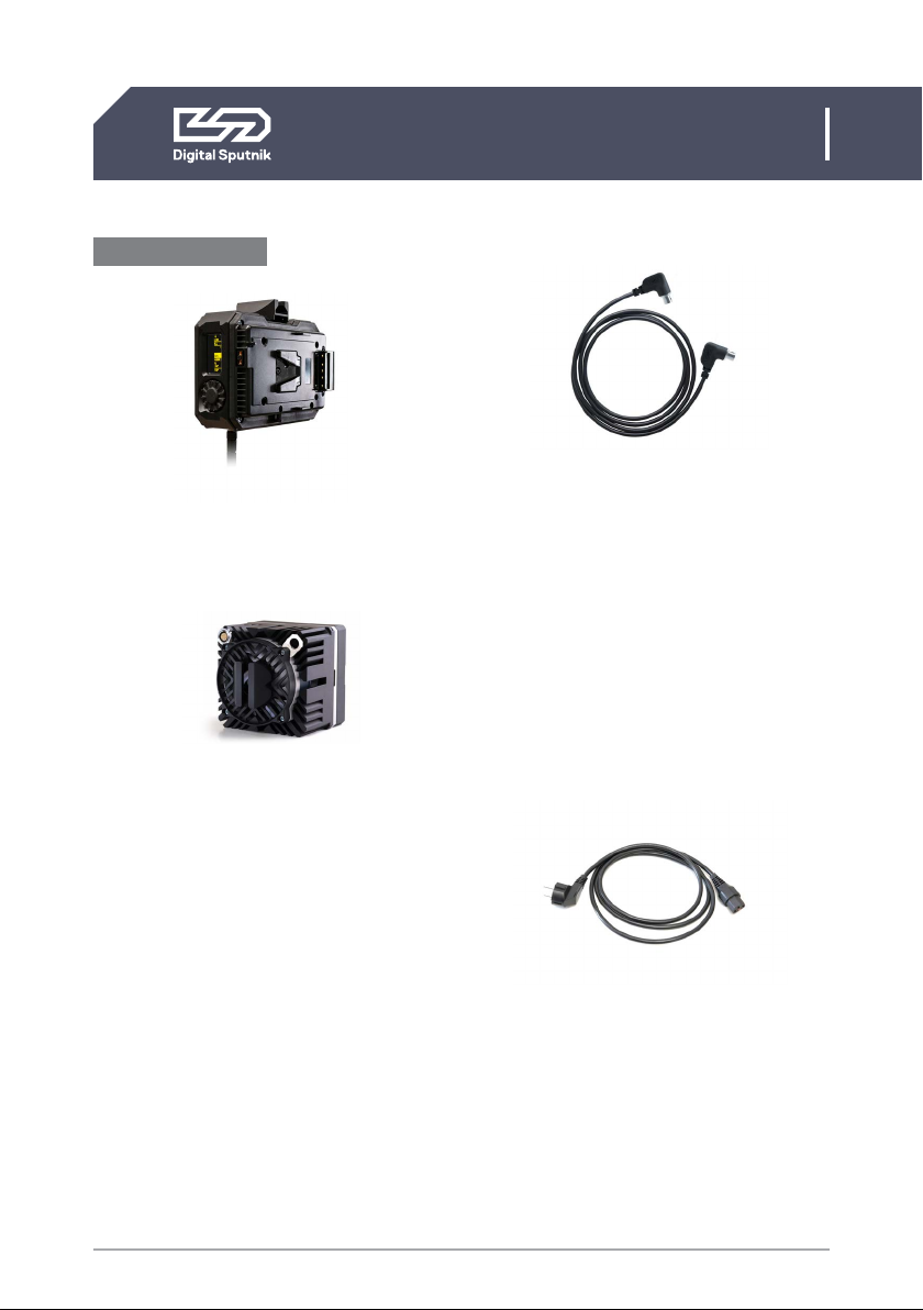
What's included:
PSU - Can also be referred to as Ballast.
The brain of the operations, gives power
and controls the light module.
Light module - has 16 RGBW LEDs
under its collimator lens. Each light module
has been factory calibrated with a specific
profile saved into it. Constant color coordi-
nates are kept through the dimming range
using high-precision, multi-dimensional
LUTs (lookup tables). The Light module
stores DMX Addressing info.
Light Module Cable - 2ft/0.75m-long
male to male connector that connects the
light module to the PSU. The light module
cables have identical connectors on their
ends and can therefore be run either way.
Does not offer couplers or daisy chaining
to other head feeder cables. Can only fit in
marked direction to its female counterpart.
All Ends of the cable are 90 Degrees for
easier cable management.
DO NOT TWIST THE HEAD OF THE CABLE
Power Cable - Standard 6ft/2m US/EU IEC
Locking power Cable.

9
DS1 User Manual
1. HARDWARE / What's included
Eccentric Lock - Multiple purpose spring
loaded locking lever.
Diffusion Clip - Clip designed to hold the
Holographic diffusion lens onto the light
module.
Tripod Mount - Modular tiltable tripod
mount that is both a baby and junior pin.
XLR Y-Cable - It is a pass-through cable
that allows you to split the DMX signal be-
tween fixtures.
Holographic Diffusion - A two-sided
holographic lens that determines the beam
spread ( either 34 or 76°) and softens the
light. Comes in 1x1, 2x1, 3x1, 2x3, and 3x3
formation.
AC/DC Converter - The DS1 AC/DC Con-
verter from Digital Sputnik provides uni-
versal 90 to 260 VAC current to the DS1
power supply.
DS 1 Module SoftBlade - The Single
Module SoftBlade from Digital Sputnik is
a triangular, blade-shaped diffusion ac-
cessory that fits over one DS module and
softens its output.

10
DS1 User Manual
1. HARDWARE / PSU interface
PSU interface
Jog-wheel
Rotating jog-wheel with push functionality.
Center of jog-wheel acts as OK button.
Screen
Gateway to your DS1 system. All color pa-
rameters, settings and system information is
presented on here.
For easier control, the orientation of the
display screen will rotate 180°depending on
the position of the PSU.
1. 2.4 Ghz WiFi module antenna
Removable WiFi antenna. DS1 has a WiFi
module built inside for wireless Art-Net
communication.
2. AC/DC Power input
The DS1 is powered by an external AC/DC
power converter. It convertsAC power at
110 - 240 V ~, 50/60Hz (nom.) to DC.
3. Male 5pin XLR input connector
For DMX512 function. Use XLR-Y cable if
wanting to daisy chain.
4. Light Module Socket
Back of the PSU features a light module
socket for communication and power
feeding purposes. Light Module Cable
ends and sockets can only be coupled in
certain position. There are red dots on the
connector and the port to act as a guide.
They must be aligned accordingly.
In this process it is important to NOT
TWIST THE HEAD OF THE CABLE.The
cable head should be pushed straight in
when aligned and pulled straight out.
• DO NOT TWIST THE HEAD
OF THE CABLE
• DO NOT HANG THE MODULE
OR PSU BY THE CABLE
• DO NOT STRAIN THE CABLE
Screen
Jog-Wheel
1
2
3
4
5
11
DS1 User Manual
1. HARDWARE / PSU interface
5. V mount battery plate
Each PSU is equipped with a single V-Lock
battery plate. The input is 12 to 36 VDC*
There is no power button to be found on
the DS1. When wanting to interrupt power,
remove battery/batteries from the PSU or
disconnect the AC/DC power connector.
*If needing more than one battery mount an extra battery
plate can be purchased and installed separately. In the
case of using two batteries, the power draw will jump
seamlessly from one battery to another when the first
battery is depleted. Extra battery plates in both V-lock
and Gold Mount systems can be purchased in the Digital
Sputnik web store and installation of the extra battery
plate can be done by the user.
On releases prior to 2018 the DS1 PSU has two V mount
battery plates by default.
ELECTRIC SHOCK HAZARD
Use only approved power
cables. Connect only to an
outlet with protective earth.
12
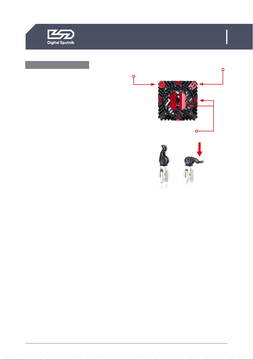
Attaching Tripod Mounts
The cornerstone of assembling DS1 system
together is the eccentric lock. The DS1 PSU,
Light Module and the Tripod Mounts all have
the same eccentric lock sockets for fixture
building purposes. This allows for great di-
versity for shaping your light fixture to your
needs.
The DS1 system comes with the Light
Module, PSU and Tripod Mount already
assembled to one fixture. This is the standard
setup of the DS1 fixture. But the fixture can
be shaped and assembled any way needed
to.
Here are some key points to keep in mind
when building your fixture.
• We recommend to start the light
fixture assembly with attaching the
tripod Mount to the module.
The tripod mount should be installed on the
correct side of the module in correlation
to the Light Module cable socket. It should
always be on the top left corner when facing
module from the back.
Position the tripod mount to the side of the
Light Module. You can see that an hourglass
shaped opening has been formed from the
eccentric lock sockets. Insert the eccentric
lock halfway to the hourglass shaped socket
and turn the head of the lock clockwise then
tighten it.
DS1 User Manual
1. HARDWARE / Attaching Tripod Mounts
If after installing the light module is able to
move on the tripod mount then the lock must
be tightened some more. Pull the eccentric
lock out halfway twist the lever head clock-
wise and tighten the lock again.
• You can use the whole stem as a junior
pin when the locking nut on the tripod
mount is removed.
• When it comes to Fastening Tripod
Mounts it is easier for the longer end of
the EC Lock to be inserted on the light
head first, then the Tripod mount can
slide on
The cable socket is always
on the top left corner
Lock sockets
Security Washer
Eccentric lock

13
DS1 User Manual
1. HARDWARE / Module setup
Module setup
The DS1 PSU has two eccentric lock mounts.
One on the short and one on the long side of
the PSU. The mounting procedure is identical
to the tripod setup.
The “default” mounting point for the module
is on the short side of the PSU. It is import-
ant to make sure before the Light Module is
Fastened to know the orientation of the PSU
so that the input sockets of the PSU (DMX IN,
AC/DC) would be facing downwards. This en-
sures that they would not get contaminated
with water or other impurities.
The Eccentric Lock socket on the long side
of the PSU is for fitting the light module so it
can be directed upwards or downwards. This
position allows more tilt using the tripod and
is the correct way to assemble the fixture
when using SoftBlade accessory.
When mounting the light fixture always se-
cure the PSU and also the light module via
the security washer positioned on the back
corner of the Light Module.
Lock socket
14
DS1 User Manual
2. CONTROL / Color page / Color control
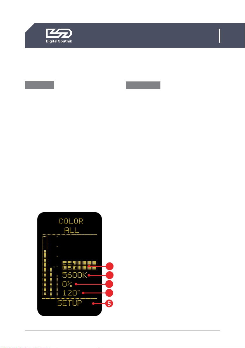
Color page
From all menu pages “COLOR” menu will
always be accessible from the bottom of
the screen for quick manual control of the
light modules.
Use the jog-wheel to navigate to “COLOR”
menu and press OK when the page name is
highlighted.
Whenever the PSU is controlled remotely
through DMX or Art-Net, and regardless
of the DMX mode used, the color mix is
always expressed in ITSH values (Intensi-
ty, Temperature, Saturation, Hue) on the
screen of the PSUs COLOR menu.
2.CONTROL
Color control
Turn the jog-wheel slowly for precise con-
trol. The incremental raise of the value is
influenced by the speed of which the but-
ton is turned.
Pressing down on the OK button for 1 sec-
ond while highlighting any ITSH parameter
will cause it to enter preset mode.
Use the jog-wheel to navigate between
presets.
1. Intensity (INT)- expressed in percentag-
es from 0 to 100, it serves as a dimmer.
On the intensity parameter, user tuned
value is always saved as the starting point
for the presets. The presets alternate be-
tween 0%, “user value” and 100%. When no
user preset is defined it will just alter be-
tween 0% and 100%.
Furthermore, holding down the OK button
for two seconds on the intensity parameter
lets you increase or decrease the intensity
by quarter, half or a full light stops.*
The whole dimming range is flicker free on
all DS systems products.
*Intensity is the only parameter with two sets of presets.
2. Temperature (TEMP) – also known as
white balance, is expressed in KELVIN units
(K). It refers to the color temperature of
the light. The lowest setting will give the
warmest light, which is 1500 Kelvin. The
maximum setting is 10,000 Kelvin, which
will give the coldest light.
4
1
2
3

15
DS1 User Manual
2. CONTROL / Color page / Color control
Temperature presets, are as follows: 1500,
3200, 5600 and 10000 K. Using the twist
knob will allow increment changes of 100K.
3. Saturation (SAT) - is the amount of
color mixed into the white light. It is also
expressed in percentages, but it can go
from -120 to 120%.
The SAT parameter has the possibility of
reaching 120% both in the negative and
positive sides. It means an absolute maxi-
mum of saturation, but be advised the area
over 100% is outside of the sRGB color
space.
When the saturation is at 120% positive
or negative the HUE color is dominant
and changing the temp of the white color
(TEMP) will show no effect on the light.
Saturation presets are: -120%, -100%,
-50%, 0%, 50%, 100%, 120%.
4. Hue - IIs the tint of color you are mix-
ing into the light. It is expressed in degrees
that refer to the color wheel. The Degree
defines the direction of color on the color
wheel, and SAT defines how much of that
color is being used/mixed with the “white
color” (TEMP), white being in the middle of
the color wheel. The default is 120 degrees,
which means Green on the top end (when
saturation is 100% or higher) and Magenta
at the bottom (when saturation is -100% or
lower).*
*For more on the subject please refer to the next illustration.

16
DS1 User Manual
2. CONTROL / Color page / Color control
Colorwheel
RED (0°)
MAGENTA (300°)
YELLOW (60°)
BLUE (240°)
GREEN (120°)
CYAN (180°)
RED (0°)
WHITE POINT CAN BE CHANGED FROM 1500 K TO 10000 K
MAGENTA (300°)
YELLOW (60°)
BLUE (240°)
1500 K
GREEN (120°)
CYAN (180
°)
SATURATION SATURATION
0% 100%
-100%
H
U
E
10000 K
SATURATION SATURATION
0%
H
U
E
100%
-100%

17
DS1 User Manual
2. CONTROL / Color page / Color control
Please note that ITSH settings will be
recorded after 6 seconds after manual in-
put and after five minutes when consis-
tent DMX values are sent by an external
controller. These will be the starting ITSH
settings after PSU reboot.
When DMX communication is active and
DMX packet values are changing constant-
ly (light animation) the ITSH values are not
saved.
It is possible to control the PSU manually
from the control panel of the PSU while
wired DMX or ArtNet is active but please
remember, the control will be transferred
back to the active remote device after 30
seconds, which means ITSH parameters
will change to those of the remote control-
ler.
• Make sure to switch off the remote
mode under “REMOTE” in the Setup
menu if you intend to control your
lights from the power supply.
5. Fan Mode - You can set the fan mode
to adapt the cooling and noise level to the
environment.
The fan mode can be manually set from the
“Color” menu of the device.
For that, navigate to the “Setup” menu
selection at the bottom. When it is high-
lighted, press the OK button for two sec-
onds and then use the Jog-Wheel to scroll
between values.
The table below shows the available options:
• FLEX: Minimum of approx 1,300 rpm
when below 45 °C. Increases linearly
to approx 2,900 rpm at 58 °C
• FAST: Always at max (approx 2,900
rpm)
• SLOW: Always at min (approx 1,300
rpm)
• OFF: Fan off until 77 °C, then turns on
at minimum speed of approx 1,300
rpm, and turns back off when the
temperature drops below 60 °C
• FLX2: Fan off until 45 °C, turns on and
linearly increases to a maximum of
approx 2,900 rpm at 58 °C *
*Note: Critical temperature for a lamp module is 80 °C,
upon which it is shut off. Covering the lamp unit even par-
tially is not recommended, as it will increase the chances
of it reaching this critical temperature. Consult with Digital
Sputnik technical support if you have questions about a
custom application in extreme conditions.
18
DS1 User Manual
2. CONTROL / Setup page
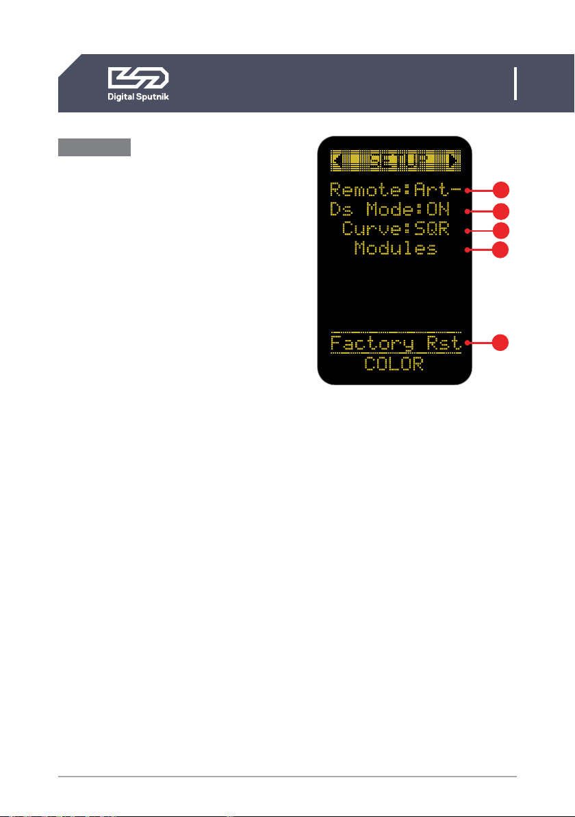
Setup Page
Allows the user to alter specific function-
ality and check working information about
the PSU and light module.
To navigate between the DS DMX page,
SETUP and WiFi pages, press OK when the
page name is highlighted and use the jog
wheel.
1. Remote - indicates the remote control
mode either DMX(Wired), Art-Net(Wire-
less) or OFF.
Select OFF to stop control by an outside
device if you intend to control your lights
from the PSU.
2. DS Mode- When turned on, the PSU will
run on DS Mode, which is a subset of the
full mode of operation, which is the DMX
mode used when DS Mode selection is set
to OFF.*
DS mode is a more simplistic approach to
DMX setup, eliminating the need to orien-
tate between DMX modes, universe selec-
tion and also making channel numbering
less cumbersome.
• DS mode is primarily meant to use
with DS DMX app for iOS. If using any
other control devices or controller
boards switch DS mode to OFF.
*Please refer to “DS DMX” section for more.
1
2
3
4
Setup page
5

19
DS1 User Manual
2. CONTROL / Setup page
3. Curve - changes the dimming curve of
the value range. It can be set so the value
is increased and decreased linearly(LIN) or
by a square factor(SQR).
Note that when using “LIN” the light output
is brighter on the whole dimming interval
but the maximum output of the module is
not altered with this setting.
4. Module data. It is possible to get an
overview of the light module information:
• 00763 Last 5 digits of light
modules serial number
• RGBW Module type whether
RGBW or WHITE
• 24°C Module temperature in
Celsius
• 75°F Module temperature in
Fahrenheit
• 3150rpm Fan RPM (Rotations
per minute)
• 237h Time counter of module
usage
• DMX 100 DMX addressing channel
assigned to the module
5. “Factory RST” - factory reset page
that will show firmware info and allows a
factory reset.*
*For more information on this topic refer to “Factory reset”
topic of this manual.
Module data
20
DS1 User Manual
2. CONTROL / DS DMX page
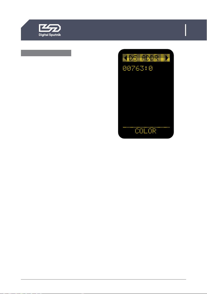
DS mode ON/DS ADDR
“DS mode” “ON” should only be used when
controlling DS1 from the “DS DMX” iOS
app. When in need to change DMX universe
or DMX mode set “DS mode” to “OFF”
under “Setup” menu.
DS mode is a more simplistic approach to
DMX setup, eliminating the need to orien-
tate between DMX modes, universe selec-
tion and also making channel numbering
less cumbersome.
When the DS Mode is in use, the DS DMX
page will be named as DS ADDR.
The only variable parameter on the DS
ADDR page is the channel number of a light
module.
DS mode ON example
• 00763:0
last 5 digits of light modules serial number
followed by a channel address
When using DS Mode, DMX personality and
universe settings are hidden and not mod-
ifiable.
The light modules connected to the PSU will
be identifiable by the last 5 digits of their se-
rial number. It is followed by light module’s
DMX CHANNEL number.
A DMX channel is the address or identifica-
tion number assigned to the light module.
It gives a controller an address number to
send DMX packets to when wanting to con-
trol the light module.
By default it is 0 when using DS mode.
DMX addressing info is stored in the light
module. This means that when switching
modules between DS PSUs the light module
will hold it's address information.
Channels are modifiable. When using the DS
mode, the channel numbers will go from 0
to 50.
Up to 50 DS light modules can be
independently controlled using DS mode
as the DS mode only listens to commu-
nication from one universe (Universe is 0,
Net 0, Subnet 0).
Therefore it is not recommended to use DS
Mode in a configuration with more than 50
light modules.
Other manuals for DS 1
1
Table of contents
Other Digital Sputnik Lighting Equipment manuals

Digital Sputnik
Digital Sputnik VOYAGER User manual

Digital Sputnik
Digital Sputnik VOYAGER User manual

Digital Sputnik
Digital Sputnik DS 1 User manual

Digital Sputnik
Digital Sputnik VOYAGER User manual

Digital Sputnik
Digital Sputnik DS Series User manual

Digital Sputnik
Digital Sputnik DS series User manual

Digital Sputnik
Digital Sputnik DS6 User manual


