DIGITAL YACHT AIT2000 User manual

IMPORTANT NOTE
The USB cable of the AIT1500/2000/3000 is designed to be used for configuring/programming the unit during in-
stallation and not for permanent connection to the boat’s Navigation PC.
If you intend to permanently connect your Class B Transponder to a PC or MAC via a USB interface, we recommend
that you use our NMEA to USB adaptor cable which will protect the unit from voltage differences, noise and elec-
trical spikes that can occur in marine installations.
AIT1500/2000/3000
CLASS B AIS
TRANSPONDERS

User Manual for AIT1500/2000/3000 V1.00
Tel: + 44 1179 554474 Web: www.digitalyachtamerica.com E-Mail: sales@digitalyachtamerica.com
Table of Contents
1. Notices.................................................................................................................................................................4
1.1 Safety Warnings.........................................................................................................................................4
1.2 Position source...........................................................................................................................................4
1.3 Compass safe distance.............................................................................................................................4
1.4 RF emissions notice..................................................................................................................................4
1.5 Warranty......................................................................................................................................................5
1.6 Disposal of this product and packaging..................................................................................................5
1.7 Accuracy of this manual............................................................................................................................5
1.8 Declaration of conformity..........................................................................................................................5
1.9 FCC notice..................................................................................................................................................5
1.10 Industry Canada notice.............................................................................................................................6
2. About Your AIS Class B Transponder............................................................................................................7
2.1 About AIS....................................................................................................................................................7
2.2 Static and dynamic vessel data...............................................................................................................7
2.3 Important information for US customers.................................................................................................8
3What's In The Box ? ..........................................................................................................................................9
3.1 Digital Yacht Software and Driver CD.....................................................................................................9
3.2 GPS Antenna..............................................................................................................................................9
3.3 Power/Data and USB Cables.................................................................................................................10
3.4 Electrical Connections.............................................................................................................................10
4. Installation.........................................................................................................................................................11
4.1 Preparing for Installation.........................................................................................................................11
4.2 Optional “Silent” switch ...........................................................................................................................12
4.3 VHF antenna cable..................................................................................................................................13
4.4 Power and data cable..............................................................................................................................13
4.5 Chart plotter..............................................................................................................................................13
4.6 Connection to a PC or Mac....................................................................................................................13
5. Installation Procedure......................................................................................................................................14
5.1 Installing the AIS transponder................................................................................................................14
5.2 Installing the external GPS antenna .....................................................................................................14
5.3 Installing the AIT1500 or external GPS antenna Below Deck ..........................................................15
5.4 Connecting to the VHF antenna............................................................................................................15

User Manual for AIT1500/2000/3000 V1.00
Tel: + 44 1179 554474 Web: www.digitalyachtamerica.com E-Mail: sales@digitalyachtamerica.com
5.5 Connecting the Power/Data cable.........................................................................................................16
5.6 Connecting a “Silent” switch (optional).................................................................................................16
5.7 Connecting to NMEA0183 compatible equipment..............................................................................17
5.8 Connection to an NMEA2000 network (not AIT1500)........................................................................18
5.9 USB Connection (optional).....................................................................................................................18
5.10 Connecting to a power supply................................................................................................................19
6. Configuring Your AIS Transponder...............................................................................................................20
6.1 Installing proAIS2 on a Windows PC....................................................................................................20
6.2 Installing proAIS2 on a Mac ...................................................................................................................21
7. Operation...........................................................................................................................................................25
7.1 Switch functions.......................................................................................................................................25
7.2 Indicator functions....................................................................................................................................25
8. Troubleshooting................................................................................................................................................27
9. Specifications....................................................................................................................................................28
User Manual for AIT1500/2000/3000 V1.00
Tel: + 44 1179 554474 Web: www.digitalyachtamerica.com E-Mail: sales@digitalyachtamerica.com
1. Notices
When reading this manual please pay attention to warnings marked with the warning triangle
shown on the left. These are important messages for safety, installation and usage of the product.
This manual is applicable to all of Digital Yacht’s range of Class B Transponders including the
AIT1500, CLASS B TRANSPONDER and AIT3000.
1.1 Safety Warnings
This equipment must be installed in accordance with the instructions provided in this manual. DO
NOT install the equipment in a flammable atmosphere such as in an engine room or near to fuel
tanks.
The Digital Yacht CLASS B TRANSPONDER is an aid to navigation and must not be relied upon
to provide accurate navigation information. AIS is not a replacement for vigilant human lookouts
and other navigation aids such as Radar. The performance of the CLASS B TRANSPONDER may
be seriously impaired if not installed as instructed in the user manual, or due to other factors such
as weather and or nearby transmitting devices. Compatibility with other systems is reliant on third
party systems recognising the standard outputs from the CLASS B TRANSPONDER. Digital
Yacht reserves the right to update and change these specifications at any time and without notice.
1.2 Position source
All marine Automatic Identification System (AIS) transponders utilise a satellite based location system
such as the Global Positioning Satellite (GPS) network. The accuracy of a GPS position fix is variable and
is affected by factors such as the antenna positioning, how many satellites are used to determine a posi-
tion and how long satellite information has been received for.
1.3 Compass safe distance
The compass safe distance of this unit is 0.5m or greater for 0.3° deviation. We suggest you always
mount the unit 1m away from any compass and check for any localised interference
1.4 RF emissions notice
Caution: The AIS transponder generates and radiates radio frequency electromagnetic energy. This
equipment must be installed and operated according to the instructions contained in this manual. Failure
to do so can result in personal injury and / or AIS transponder malfunction. Caution: Never operate the
AIS transponder unless it is connected to a VHF antenna.
To maximise performance and minimise human exposure to radio frequency electromagnetic energy you
must make sure that the antenna is mounted at least 1.5 metres away from the AIS transponder and is
connected to the AIS transponder before power is applied. The system has a Maximum Permissible Ex-
posure (MPE) radius of 1.5m. This has been determined assuming the maximum power of the AIS tran-
sponder and using antennas with a maximum gain of 3dBi.The antenna should be mounted 3.5m above
the deck in order to meet RF exposure requirements. Higher gain antennas will require a greater MPE
radius. Do not operate the unit when anyone is within the MPE radius of the antenna (unless they are
shielded from the antenna field by a grounded metallic barrier). The antenna should not be co-located or

User Manual for AIT1500/2000/3000 V1.00
Tel: + 44 1179 554474 Web: www.digitalyachtamerica.com E-Mail: sales@digitalyachtamerica.com
operated in conjunction with any other transmitting antenna. The required antenna impedance is 50
Ohms.
1.5 Warranty
The CLASS B TRANSPONDER is supplied with a standard 2 year return to base warranty as defined in
the accompanying warranty information. Any attempt to tamper with or damage this product will invalidate
the warranty. Physical damage and damage caused by salt water ingress are not covered under this
warranty.
1.6 Disposal of this product and packaging
Please dispose of the AIS transponder in accordance with the European WEEE Directive or with the ap-
plicable local regulations for disposal of electrical equipment. Every effort has been made to ensure the
packaging for this product is recyclable. Please dispose of the packaging in an environmentally friendly
manner.
1.7 Accuracy of this manual
The AIS transponder may be upgraded from time to time and future versions of the AIS transponder may
therefore not correspond exactly with this manual. Information contained in this manual is liable to change
without notice. The manufacturer of this product disclaims any liability for consequences arising from
omissions or inaccuracies in this manual and any other documentation provided with this product.
1.8 Declaration of conformity
Digital Yacht declare that this product is in compliance with the essential requirements and other provi-
sions of the R&TTE directive 1995/5/EC.
The product carries the CE mark, notified body number and alert symbol as required by the R&TTE di-
rective.
The CLASS B TRANSPONDER is intended for sale in the following member states: United Kingdom,
France, Spain, Sweden, Austria, Netherlands, Portugal, Denmark, Norway, Belgium, Italy, Finland, Ire-
land, Luxembourg, Germany and Czech Rep.
1.9 FCC notice
This equipment has been tested and found to comply with the limits for a class B digital device, pursuant
to part 15 of the FCC Rules. These limits are designed to provide reasonable protection against harmful
interference in a residential installation.
This equipment generates, uses and can radiate radio frequency energy and, if not installed and used in
accordance with the instructions, may cause harmful interference to radio communications.
This device complies with part 15 of the FCC Rules. Operation is subject to the following two conditions:
(1) This device may not cause harmful interference, and (2) this device must accept any interference re-
ceived, including interference that may cause undesired operation.
Changes or modifications not expressly approved by the party responsible for compliance could void the
user's authority to operate the equipment.

User Manual for AIT1500/2000/3000 V1.00
Tel: + 44 1179 554474 Web: www.digitalyachtamerica.com E-Mail: sales@digitalyachtamerica.com
WARNING: It is a violation of the rules of the Federal Communications Commission to input an
MMSI that has not been properly assigned to the end user, or to otherwise input any inaccurate
data in this device.
1.10 Industry Canada notice
This device complies with Industry Canada licence-exempt RSS standard(s). Operation is subject to the
following two conditions:
1. This device may not cause interference, and
2. This device must accept any interference, including interference that may cause undesired opera-
tion of the device.
This Class B digital apparatus complies with Canadian ICES-003.
Le présent appareil est conforme aux CNR d'Industrie Canada applicables aux appareils radio exempts
de licence. L'exploitation est autorisée aux deux conditions suivantes :
1. L'appareil ne doit pas produire de brouillage, et
2. L'utilisateur de l'appareil doit accepter tout brouillage radioélectrique subi, même si le brouillage
est susceptible d'en compromettre le Fonctionnement.
Cet appareil numérique de la classe B est conforme à la norme NMB-003 du Canada.

User Manual for AIT1500/2000/3000 V1.00
Tel: + 44 1179 554474 Web: www.digitalyachtamerica.com E-Mail: sales@digitalyachtamerica.com
2. About Your AIS Class B Transponder
2.1 About AIS
The marine Automatic Identification System (AIS) is a location and vessel information reporting system. It
allows vessels equipped with AIS to automatically and dynamically share and regularly update their posi-
tion, speed, course and other information such as vessel identity with similarly equipped vessels. Position
is derived from the Global Positioning System (GPS) and communication between vessels is by Very
High Frequency (VHF) digital transmissions.
There are a number of types of AIS device as follows:
Class A transponders
These are similar to class B transponders, but are designed to be fitted to large vessels such as cargo
ships and large passenger vessels. Class A transponders transmit at a higher VHF signal power than
class B transponders and therefore can be received by more distant vessels. They also transmit Class A
transponders are mandatory on all vessels over 300 gross tonnes on international voyages and certain
types of passenger vessels under SOLAS regulations.
Class B transponders
Similar to class A transponders in many ways, but are normally lower cost due to the less stringent per-
formance requirements. Class B transponders transmit at a lower power and at a lower reporting rate
than class A transponders.
AIS base stations
AIS base stations are used by Vessel Traffic Systems to monitor and control the transmissions of AIS
transponders.
Aids to Navigation (AtoN) transponders
AtoNs are transponders mounted on buoys or other hazards to shipping which transmit details of their
location to the surrounding vessels.
AIS receivers
AIS receivers will generally receive transmissions from class A transponders, class B transponders,
AtoNs and AIS base stations but do not transmit any information about the vessel on which they are in-
stalled.
This product is an AIS Class B transponder.
2.2 Static and dynamic vessel data
There are two categories of information transmitted by an AIS transponder: static and dynamic data.
The vessel's dynamic data, which includes location, speed over ground (SOG) and course over ground
(COG), is calculated automatically using the internal GPS receiver.

User Manual for AIT1500/2000/3000 V1.00
Tel: + 44 1179 554474 Web: www.digitalyachtamerica.com E-Mail: sales@digitalyachtamerica.com
Static data is information about the vessel which must be programmed into the AIS transponder. This
includes:
Maritime Mobile Service Identity (MMSI)
Vessel name
Vessel call sign (if available)
Vessel type
Vessel dimensions
In most countries the operation of an AIS transponder is included under the vessel's marine VHF licence
provisions. The vessel on to which the AIS unit is to be installed must therefore possess a current VHF
radiotelephone licence which lists the AIS system, vessel Call Sign and MMSI number.
An MMSI number is required in order for the AIS transceiver to operate. Please contact the rele-
vant authority in your country for more information.
2.3 Important information for US customers
There are specific laws in the USA regarding the configuration of AIS class B transponders.
If you are a US resident and intend to use your AIS class B transponder in US waters, you should make
sure that your retailer has configured your product prior to supplying it to you. If your AIS transponder has
not been pre-configured please contact your dealer for details of how to have it configured.

User Manual for AIT1500/2000/3000 V1.00
Tel: + 44 1179 554474 Web: www.digitalyachtamerica.com E-Mail: sales@digitalyachtamerica.com
3 What's In The Box ?
These items are included with your AIS transponder purchase.
CLASS B TRANSPONDER (with integrated connections for power, NMEA and USB)
GPS ANTENNA(except AIT1500 which has an internal GPS antenna)
QUICK START GUIDE
DIGITAL YACHT SOFTWARE AND DRIVER CD
The following sections give a brief overview of each item. Please ensure all items are present and if any of
the items are not present contact your dealer.
3.1 Digital Yacht Software and Driver CD
The CD supplied with the package contains the following:
proAIS2 software tool necessary to configure the AIS transponder. Two versions of the program
are on the CD, one for PCs running Windows and one for Macs running OSX (Intel only). Please
refer to section 6 for details of the configuration process and how to use the proAIS2 tool.
NOTE - products supplied in the USA will be pre-programmed by a dealer or competent authority.
USB drivers required by PCs and/or Macs so that they know how to talk to the AIS transponder.
The drivers are automatically installed during the proAIS2 installation process.
Alternative language versions of this manual.
A complete set of manuals for all Digital Yacht Products
All of the latest Tech Support Notes, that provide additional installation and support information of
all Digital Yacht products
SmarterTrack Lite AIS Viewing Software which is a simple AIS display program for using with your
AIS Transponder on a Windows PC
Other useful programs and utilities
3.2 GPS Antenna
The AIT2000/3000 transponders require an external GPS antenna (as supplied). The supplied GPS an-
tenna is designed to be fitted to a standard 1”x14 TPI threaded VHF pole mount, which are available in
many different styles from all good marine electronic dealers and chandleries.
It is possible to use any existing GPS antenna as long as it is a passive GPS type antenna with a 3v or 5v
pre-amplifier. It is not possible to connect another GPS unit to the CLASS B TRANSPONDER via NMEA.
The international Class B Transponder specification states that a transponder must have its own GPS to
ensure that it can work entirely on its own without being reliant upon other external equipment.
The GPS antenna supplied with the Class B Transponder comes complete with 10m of cable and is ter-
minated in a TNC connector. The cable can be lengthened but this should be done using a suitable TNC
(Male) to TNC (Female) extension cable or carried out by an experienced and qualified Marine Electron-
ics Dealer. Any joins in the cable should be made to a professional standard suitable for the marine en-
vironment.
User Manual for AIT1500/2000/3000 V1.00
Tel: + 44 1179 554474 Web: www.digitalyachtamerica.com E-Mail: sales@digitalyachtamerica.com
The AIT1500 has a built-in GPS antenna which is designed to give good GPS reception even when
mounted down below. The antenna is located in the top of the unit and it is important that the AIT1500 is
mounted vertically with just a layer of fibre-glass above the unit, no metallic or electrical objects.
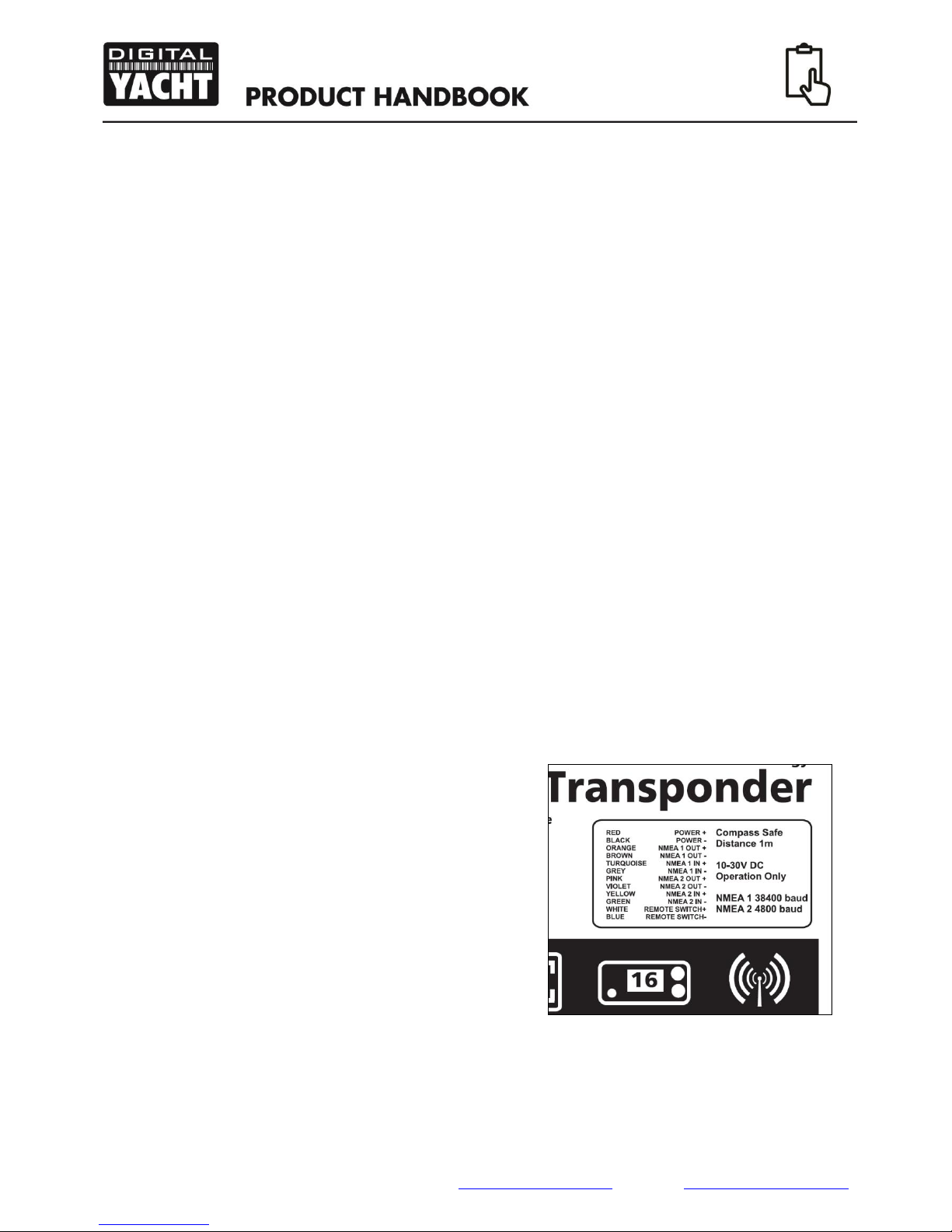
3.3 Power/Data and USB Cables
The integral 1 metre Power and Data cable allows power, NMEA 0183 data and an optional “Silent Switch”
to be connected to the CLASS B TRANSPONDER transponder. This twelve core cable can be extended
using suitable marine grade cables . To aid installation, a table of the wire connections and colours, is
printed on the CLASS B TRANSPONDER product label.
The integral 1 metre USB cable allows a power and data connection between the CLASS B TRAN-
SPONDER and a computer. The CLASS B TRANSPONDER will take enough power from the USB con-
nection to operate as an AIS Receiver. This is useful for initial programming/configuration of the CLASS B
TRANSPONDER with your MMSI number and other vessel data, which can be done at home or in the
office without the need of an additional 12v DC supply. It should be noted that the CLASS B TRAN-
SPONDER will not operate as a Transponder without an external power supply connected to the Red and
Black Wires of the Power/Data cable.
3.4 Electrical Connections
Our Class B Transponders have the following electrical connections:
Power supply 12v or 24v
Two NMEA0183 data ports for connection to chart plotters and other NMEA0183 compatible
equipment
USB for connection to a PC or Mac
External switch input for silent mode control (on power/data cable)
NMEA2000 port for connection to NMEA2000 compatible equipment (Only AIT2000+AIT3000)
In addition there are two other connections for the VHF antenna and the external GPS antenna.
Figure 1 shows the electrical connections to the
Power/Data cable that is common to all three models
of our Class B Transponder.
It is good etiquette to fit a “Silence Switch” to a Class B
transponder and to only transmit your position in poor
weather or when crossing busy shipping lanes/areas.
The transponder will operate on “Silent Mode” when the
Blue and White wires of the Power/Data cable are
connected together. In “Silent Mode” the transponder
continues to receive other AIS targets, but it does not
transmit its own position to other vessels.
Figure 1
User Manual for AIT1500/2000/3000 V1.00
Tel: + 44 1179 554474 Web: www.digitalyachtamerica.com E-Mail: sales@digitalyachtamerica.com
4. Installation
4.1 Preparing for Installation
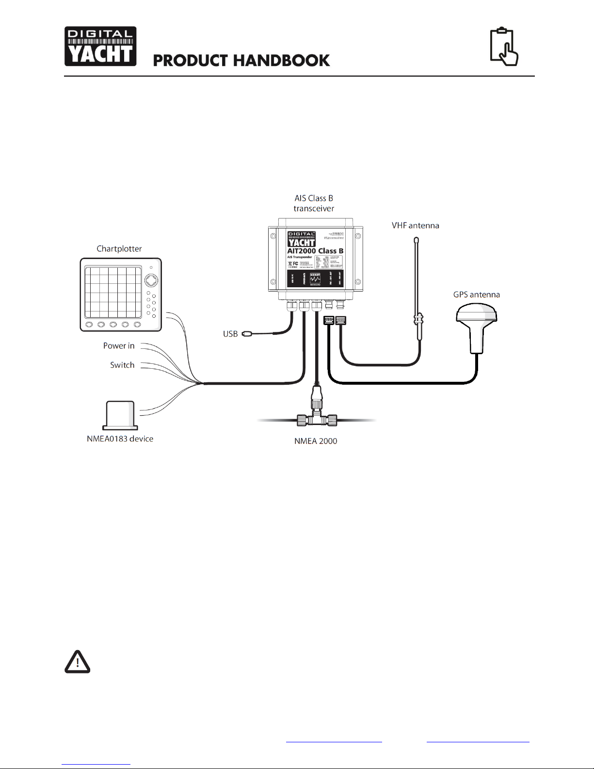
Figure 2 below shows a typical installation of an CLASS B TRANSPONDER. Please take the time to fa-
miliarise yourself with the system elements and their connections prior to attempting installation.
In addition to the items provided with your AIS transponder the following items will be required for instal-
lation:
VHF antenna or a suitable Class B Transponder Splitter if you intend to use your existing VHF
antenna (our AIT3000 has its own built-in splitter).
Four M4 screws or other fixings for the CLASS B TRANSPONDER appropriate to the mounting
location
A suitable 1”x14TPI thread mount for the GPS Antenna (not supplied)
Connection to a suitable VHF antenna will be required for the AIS transponder to operate. A standard
marine band VHF antenna can be used, however, many manufacturers are now offering AIS tuned
(162MHz) antennas that offer even better performance.
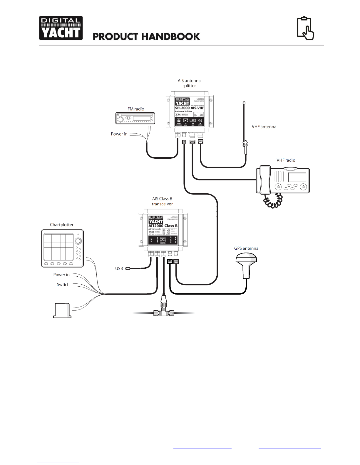
Alternatively, if you wish to use the vessel’s existing VHF antenna, our SPL2000 antenna splitter
product is available which allows the existing antenna to be used by the VHF voice radio and the
Class B Transponder.
Figure 2
User Manual for AIT1500/2000/3000 V1.00
Tel: + 44 1179 554474 Web: www.digitalyachtamerica.com E-Mail: sales@digitalyachtamerica.com
Below is a typical splitter installation diagram showing how our AIT2000 (or AIT1500) and SPL2000
Splitter should be connected to the vessel’s existing VHF antenna.
4.2 Optional “Silent” switch
A switch can be connected to the transponder to enable and disable 'silent mode'. A standard “Single
Pole Single Throw” (SPST) toggle switch is required to use this feature. When the switch is “closed” the
Class B Transponder stops transmitting (“Silent Mode”) and when the switch is “open” the Class B
Transponder starts transmitting again.
Figure 3

User Manual for AIT1500/2000/3000 V1.00
Tel: + 44 1179 554474 Web: www.digitalyachtamerica.com E-Mail: sales@digitalyachtamerica.com
4.3 VHF antenna cable
Please check that the VHF antenna you intend to use has sufficient cable to reach between the VHF
antenna and the AIS transponder unit. If it is not sufficient you will need an extension cable. Please con-
tact your dealer for details of suitable products. For reference the VHF antenna connector type on the AIS
transponder unit is BNC female, and is intended to mate with a BNC male connector.
All VHF antenna cables should be 50ohm coax (such as RG58) and 75ohm TV antenna coax cable
should not be used. VHF antenna cable runs should be kept as short as possible to avoid unwanted
signal attenuation and loading problems.
4.4 Power and data cable
The AIS transponder unit is supplied with a 1m long power and data cable integrated into the unit. If you
require longer cables to reach your power supply, please ensure the cables are capable of carrying cur-
rents of up to 2A peak and 0.5A average. Means of connecting the cables together will also be required.
The use of Scotchlok type connectors is recommended for this purpose.
4.5 Chart plotter
To display received AIS messages as other vessels on your chart plotter, you will need to connect your
AIS transponder to your chart plotter. This is usually done via NMEA 0183 or via NMEA 2000, which are
the marine industry standards for digital communication.
Please refer to the user manual supplied with your chart plotter for details of how to connect and configure
your chart plotter for use with AIS devices. For NMEA 0183 data connections, your chart plotter should be
configured to accept NMEA data at 38400 baud (sometimes referred to as 'NMEA HS' in the plotter con-
figuration menu). You may also need to enable the display of AIS targets in the chart options.
Alternatively if you use an NMEA2000 network on your vessel it is possible to connect the AIS tran-
sponder (except the AIT1500) to the NMEA2000 network via the integral cable. Assuming that you are
connecting to an existing NMEA2000 network, you should be able to simply “plug and play” the Class B
Transponder in to a spare “T-piece” connector on the network.
Please refer to your dealer and to the chart plotter manual for more information on NMEA2000 network-
ing.
4.6 Connection to a PC or Mac
If you choose to use a PC or Mac with suitable charting software to display received AIS messages as
other vessels, this can be accomplished by connecting the USB cable integrated into the unit.
For permanent USB connection to a PC or Mac, we strongly recommend the use of one of our NMEA to
USB Adaptor cables. The USB cable that comes with the Class B Transponders is connected directly to
the micro-processor for configuration and programming purposes. It does not have galvanic isolation or
protection against static and voltage spikes that can often happen on boats, particularly blue water yachts
travelling in hot or tropical locations.
User Manual for AIT1500/2000/3000 V1.00
Tel: + 44 1179 554474 Web: www.digitalyachtamerica.com E-Mail: sales@digitalyachtamerica.com
5. Installation Procedure
It is strongly recommended that you read all of the instructions in this manual prior to installation.
If after reading this manual you are unsure about any element of the installation process please contact
your dealer for advice.
The following sections explain the installation process step by step for each of the main elements of the
system.
5.1 Installing the AIS transponder
Please note the following guidelines when selecting a location for your AIS transponder:
The AIS transponder must be fitted in a location where it is at least 0.5m from a compass or any
magnetic device.
There should be adequate space around the AIS transponder for routing of cables. See drawing
below for details of the AIS transponder dimensions.
The ambient temperature around the AIS transponder should be maintained between -25°C and
+55°C.
The AIS transponder should not be located in a flammable or hazardous atmosphere such as in
an engine room or near to fuel tanks.
The AIS transponder is fully waterproof to ingress protection rating IPx5, however it is recom-
mended that the AIS transponder is not subjected to extended periods of exposure to spray or
submersion.
It is recommended that the AIS transponder is installed in a 'below decks' environment.
It is acceptable to mount the AIT2000 and AIT3000 either vertically or horizontallym BUT the
AIT1500 must be mounted vertically with only fibreglass directly above the unit.
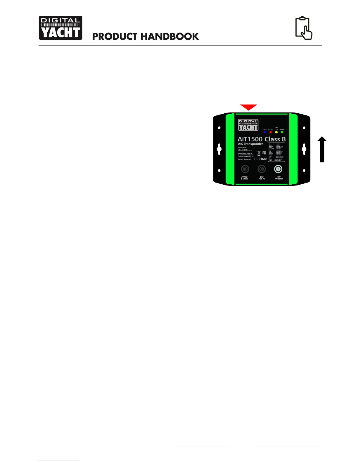
To mount the AIT2000 and AIT3000 units, remove the green décor strips to expose 4 mounting
holes to screw the unit to a suitable bulkhead or surface.
The AIS transponder should be mounted in a location where the indicators are readily visible as
these provide important information on the status of the AIS transponder.
AIT1500 owners should refer to section 5.3 prior to finally fixing the unit in place.
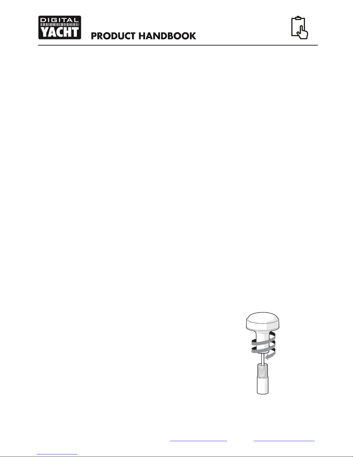
5.2 Installing the external GPS antenna
For mounting of the optional external GPS antenna
you will require a 1” x 14 TPI thread pole, deck base
or rail mount
You should ensure the GPS antenna has a good clear
view of the entire sky.
It is not recommended that the GPS antenna is
mounted up a mast where the motion of the vessel will
cause the antenna to swing and potentially reduce the
accuracy of the GPS position.
Do not mount your antenna in the direct path of a ra-
dar transmitter.
Feed the ten metre long cable attached to the GPS antenna
cable through the pole and screw the antenna onto the pole mount as shown in Figure 4.
Figure 4
User Manual for AIT1500/2000/3000 V1.00
Tel: + 44 1179 554474 Web: www.digitalyachtamerica.com E-Mail: sales@digitalyachtamerica.com
Route the cable to your AIS transponder unit, adding any necessary extension cables.
Connect the cable from the GPS antenna to the GPS connector on the AIS transponder
5.3 Installing the AIT1500 or external GPS antenna Below Deck
The high sensitivity GPS receiver in our Class B
Transponders is capable of receiving GPS position
fixes even when the GPS antenna is mounted below
deck. This is one of the reasons why Digital Yacht
released the AIT1500 with an internal GPS antenna.
For optimum GPS performance we would always
recommend mounting the GPS antenna on deck, but
many owners will get very good performance with the
GPS antenna mounted below deck and benefit from a
simpler, easier and cleaner installation.
This is only possible on fibre-glass (GRP) hulled boats
and care should be taken to place the AIT1500 or
external GPS antenna in a location where there is just
a layer of fibre-glass above the antenna, with no me-
tallic or electrical objects above the antenna.
The AIT1500 or external GPS antenna must be mounted vertically. The location of the GPS an-
tenna inside the AIT1500 is shown in Fig.5
Before finally securing the AIT1500 or GPS antenna we recommend that the GPS reception is
checked using the supplied proAIS2 software for PC/Mac. Run the proAIS2 software, view the
“GNSS Status” page and ensure that the GPS is receiving strong signals –all green bars with
signal strength >20dBHz.
5.4 Connecting to the VHF antenna
Route the cable from the VHF antenna or splitter to the AIS transponder and connect to the VHF con-
nector on the AIS transponder.
A standard marine band VHF antenna or AIS antenna should be used with the AIS transponder.
The connector type on the AIS transponder is a BNC. Your chosen VHF antenna requires a BNC
male connector to mate with this. If your VHF antenna does not use this type of connector please
contact your dealer for details of available adaptors.
If you are using an antenna splitter, connect the AIS connection on the splitter to the VHF (BNC)
connector on the Class B Transponder.
NOTE –if you intend to use a splitter, it is important that the splitter is designed for use with a
Class B Transponder. Some lower cost splitters are only designed for use with AIS receivers and
will not work properly with the Class B Transponder.
Our SPL2000 Splitter features the latest “Zero Loss” technology that lets the transponder share
the main antenna with the VHF radio with none of the VHF reception loss that used to be the
problem with traditional splitters.
GPS
Antenna
This
Way
Up
Figure 5

User Manual for AIT1500/2000/3000 V1.00
Tel: + 44 1179 554474 Web: www.digitalyachtamerica.com E-Mail: sales@digitalyachtamerica.com
5.5 Connecting the Power/Data cable
The integral 1m Power/Data cable allows connection of DC power, NMEA data (two inputs and two out-
puts) and the remote Silent Switch. The cable is terminated inside the unit and the other end of the cable
has twelve colour coded bare wires ready for connection.
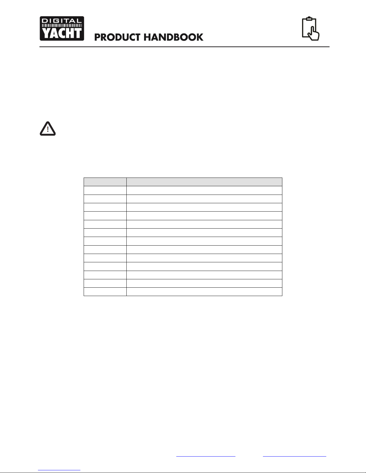
Table1 below lists the function of each colour coded wire for reference.
Wire colour
Description
Function
RED
Power in +
Power supply connections
BLACK
Power in -
BLUE
Switch in-
put-
External switch connection for silent mode
WHITE
Switch in-
put+
ORANGE
NMEA0183
port 1 TX+
High speed NMEA0183 output (38,400 baud) intended for
connection to chart plotters
BROWN
NMEA0183
port 1 TX-
TURQUOISE
NMEA0183
port 1 RX+
High speed NMEA0183 input (38,400 baud)
Not normally used
GREY
NMEA0183
port 1 RX-
PINK
NMEA0183
port 2 TX+
Low speed NMEA0183 Output (4,800baud) intended for con-
nection to other NMEA0183 devices requiring a GPS feed. Note
AIS data is not available on this output.
VIOLET
NMEA0183
port 2 TX-
YELLOW
NMEA0183
port 2 RX+
Low speed NMEA0183 input (4,800baud) intended for connec-
tion to other NMEA0183 compatible sensors for multiplexing of
data to the chart plotter
GREEN
NMEA0183
port 2 RX-
Table 1
5.6 Connecting a “Silent” switch (optional)
A toggle switch can be connected to the AIS transponder to provide remote control of silent mode.
Connect the toggle switch between the White(+) and Blue(-) wires as shown below. Connection of an
external switch to toggle silent mode is optional and not essential for normal operation of the product.
Figure 6
User Manual for AIT1500/2000/3000 V1.00
Tel: + 44 1179 554474 Web: www.digitalyachtamerica.com E-Mail: sales@digitalyachtamerica.com
5.7 Connecting to NMEA0183 compatible equipment
The Class B Transponder has two independent NMEA0183 data ports which are pre-configured at the
following data rates; Port 1 = 38400 baud and Port 2 = 4800 baud. Each port has a two wire Input and two
wire Output, which are colour coded as shown in Table 1.
Connect the wires to the appropriate connections on your NMEA0183 compatible equipment. Please re-
fer to your equipment manual for more information and pay particular attention to any menu settings that
must be configured to configure and display AIS or other NMEA data.
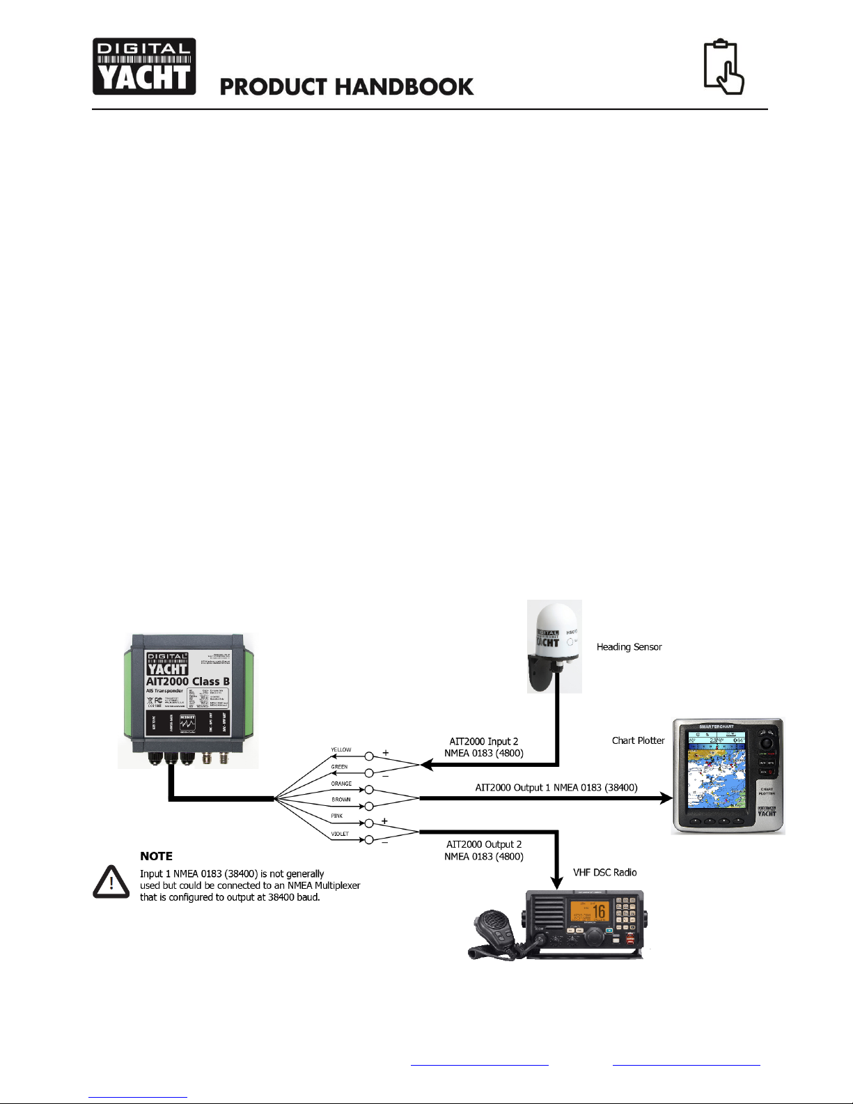
The high speed NMEA Output 1 connects to a chart plotter, while the low speed NMEA Input 2 and
Output 2 connect to other NMEA0183 devices. A multiplexing feature is provided, which means any
messages received on the low speed Input 2 port are automatically transmitted on the high speed Output
1 port. This is particularly useful when using a chart plotter having only a single NMEA0183 port.
Instrument data or additional sensors can be connected to the AIS transponder via the low speed port.
This data, plus the AIS and GPS data is transmitted on the high speed Output 1 port to the chart plotter.
Please ensure your equipment is configured to use the correct baud rate for the port it is connected to.
On many vessels fitted with a modern VHF Radio that requires GPS data for the DSC functions, the low
speed NMEA Output 2 can be used to give GPS data to the VHF radio. On this port are the following
common NMEA 0183 GPS position sentences; GLL, GGA and RMC.
Figure 7 shows a typical installation with NMEA0183 data received on Input 1 being combined with the
transponder’s own AIS and GPS data and sent to the Chart Plotter on Output 1. The GPS inside the
Class B Transponder provides the VHF DSC radio with GPS position data on Output 2 (4800 baud).
Figure 7
User Manual for AIT1500/2000/3000 V1.00
Tel: + 44 1179 554474 Web: www.digitalyachtamerica.com E-Mail: sales@digitalyachtamerica.com
5.8 Connection to an NMEA2000 network (not AIT1500)
The AIT2000 and AIT3000 Transponders also have an N2Net connection which is Digital Yacht’s
NMEA2000 compliant interface. To connect to other NMEA2000 products, simply find or add a spare
NMEA2000 “T” piece on the existing NMEA2000 network and connect the receiver’s N2Net connector to
the “T” piece.
The N2Net cable is just under 1m long and is terminated in an NMEA2000 Micro Male Connector.
The AIS200N2NET does not take any power from the NMEA2000 network.
The Load Equivalency Number (LEN) of the Class B Transponder is 1.
The Class B Transponder outputs AIS and GPS data on to the network (GPS added with V1.7 firmware),
it does not provide any other NMEA0183 to NMEA2000 conversion.
The list of AIS PGNs that the Class B Transponder outputs is listed below in Table 2;
PGN No.
PGN Title
129038
Class A Position Report
129039
Class B Position Report
129040
Class B Extended Position Report
129793
AIS UTC and Date report
129794
AIS Class A Static and Voyage Related Data
129800
AIS UTC/Date Inquiry
129801
AIS Address Safety Message
129802
AIS Broadcast Safety Message
129810
AIS Class B static data part B
129809
AIS Class B static data part A
129041
AtoN position report
129025
Position –rapid update
129026
COG/SOG –rapid update
Table 2
5.9 USB Connection (optional)
When connected to a PC or MAC via the USB cable, the Transponder will only get enough power from the
computer to power the microprocessor and the AIS receiver. This allows you to program the MMSI
number and other static data at home or in the office prior to installation. The Transponder will not
transmit or get a valid GPS position fix when only powered from the USB interface and the RED Status
LED will always be lit when powered from the USB cable.
If you need to extend the USB cable, please use a USB extension cable that is no more than 4m in length.
The maximum length of USB cable without the use of a powered extender cable or Hub is 5m.
Please do not plug in the USB cable of the Transponder to your PC/Mac until after you have installed the
proAIS2 software, which also installs the USB drivers for the Transponder. Installing proAIS2 is covered
in section 6 - Configuration.

User Manual for AIT1500/2000/3000 V1.00
Tel: + 44 1179 554474 Web: www.digitalyachtamerica.com E-Mail: sales@digitalyachtamerica.com
After the Transponder is configured, the USB connection can be used to provide data to navigation pro-
gram running on a PC or Mac. Please note that only one navigation program at a time can receive data
from the Transponder.
The Transponder’s USB interface is not fully isolated and high levels of static or large differences in
ground voltages between the computer supply and the boat’s DC supply can damage the Transponder’s
USB interface. For maximum reliability, if you intend to permanently connect the Transponder to a com-
puter, we recommend using an NMEA to USB adaptor connected to the Transponder’s NMEA0183 out-
put which provides an extra level of protection/isolation and can avoid costly damage to the Transponder.
5.10 Connecting to a power supply
The Class B Transponder should be connected to the ship’s 12V or 24V DC power supply typically pro-
vided by the vessel's battery.
It is recommended that crimped and soldered lugs are used to connect the AIS transponder to the power
source. It is recommended that the power supply is connected via a suitable circuit breaker and/or 3A
fuse
Connect the red wire to a 12V or 24V power supply positive terminal.
Connect the black wire to the supply negative terminal.
The Class B Transponder will only operate correctly as a Class B transponder when it is connected to an
external supply that has a voltage greater than 9.6v. If the supply voltage is less than 9.6v or the Class B
Transponder is only powered through the USB cable, then the Class B Transponder’s GPS circuitry will
be powered down and the unit will only operate in AIS Receiver mode.
The Class B Transponder can be powered from the USB port for configuring the unit (program-
ming MMSI number, etc.) which is useful for initially setting the unit up when first purchased. The
following section explains how to configure the Class B Transponder for correct operation.

User Manual for AIT1500/2000/3000 V1.00
Tel: + 44 1179 554474 Web: www.digitalyachtamerica.com E-Mail: sales@digitalyachtamerica.com
6. Configuring Your AIS Transponder
Until correctly configured your AIS class B transponder will only receive AIS messages and will not
transmit AIS messages. Before you can configure your Class B Transponder, it is necessary for you to
have a unique MMSI number that has been issued to you by the relevant radio or marine authority in your
country. If you already have an MMSI number for your DSC VHF Radio, then this is the MMSI number
that you will also program in to the Class B Transponder.
There are two potential ways in which your AIS transponder can be configured:
a) Configuration in advance by your dealer or installer, in which case you will need to provide them
with all of the boat’s data i.e. MMSI number, call sign, vessel name, etc.
b) Configuration using proAIS2
Providing it is acceptable to do so under your local legislation it is possible to configure your AIS tran-
sponder yourself using the proAIS2 software provided with the product. proAIS2 is available for both
Windows and Mac OSX and setup/installer programs for each operating system are included on the Dig-
ital Yacht Software and Driver CD, supplied with the Class B Transponder.
The proAIS2 software provides the facility to configure, monitor and diagnose issues with your AIS tran-
sponder. proAIS2 can provide assistance when ensuring that a satisfactory GPS signal is being received.
It can also display alarm messages generated by the transponder regarding poor VHF antenna quality or
that the power being supplied is outside the range specified for operation. proAIS2 can also be used to
activate 'silent mode' which disables AIS transmissions.
Once your Class B Transponder is configured, it is not necessary to run proAIS2 again unless you want to
use it for controlling or fault finding the Class B Transponder. If you do not have a compatible chart plotter
or PC program for displaying AIS data, then a free copy of our SmarterTrack Lite software is also included
on the CD which will run on a Windows PC and provide an AIS “radar” type display of targets on your PC
screen.
If your AIS transponder has been configured for you by your dealer or installer you can proceed to the
Operation section.
For configuration purposes only, it is possible to power the AIS transponder via its USB connection. This
is useful if you wish to configure your AIS transponder away from the vessel power supply. The AIS
transponder will not transmit any data or acquire a GPS position fix whilst powered by USB, but it will
receive AIS targets if the AIS/VHF antenna is connected and you are in range of other AIS equipped
vessels.
6.1 Installing proAIS2 on a Windows PC
For a Window’s PC, insert the Digital Yacht Software and Drivers CD in to your PC and browse to the
“proAIS2 for AIT1500+AIT2000+AIT3000” folder and then double click on the “proAIS2_V1-4_Windows”
sub-folder and run the Setup.Exe file by double clicking on it.
Follow the on-screen instructions, until the Setup program finishes installing the proAIS2 application and
the USB drivers for the transponder.
Other manuals for AIT2000
4
This manual suits for next models
2
Table of contents
Other DIGITAL YACHT Marine Radio manuals

DIGITAL YACHT
DIGITAL YACHT AIT250 Datasheet

DIGITAL YACHT
DIGITAL YACHT AIT5000 User manual

DIGITAL YACHT
DIGITAL YACHT AIT3000 Quick guide

DIGITAL YACHT
DIGITAL YACHT AIT1500 Quick guide

DIGITAL YACHT
DIGITAL YACHT AIT1000 Datasheet

DIGITAL YACHT
DIGITAL YACHT NOMAD Quick guide

DIGITAL YACHT
DIGITAL YACHT AIT2000 Specification sheet

DIGITAL YACHT
DIGITAL YACHT AIT2000 User manual

DIGITAL YACHT
DIGITAL YACHT AIT2000 Quick guide

DIGITAL YACHT
DIGITAL YACHT iAIS TX Quick guide


