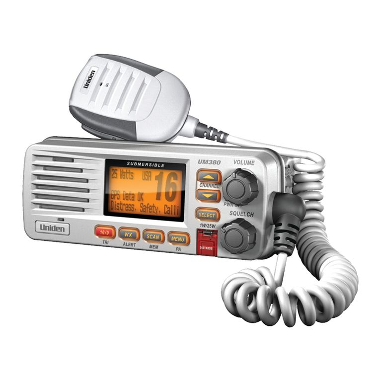
Icom MA-510TR User manual

INSTRUCTION MANUAL
This device complies with Part 15 of the FCC
rules. Operation is subject to the following two
conditions: (1) This device may not cause harmful
interference, and (2) this device must accept any
interference received, including interference that
may cause undesired operation.
CLASS B AIS TRANSPONDER
MA-510TR

i
Thank you for choosing this Icom product.
This product was designed and built with Icom’s state of the art technology and
craftsmanship. With proper care, this product should provide you with years of trouble-
free operation.
■Important
READ ALL INSTRUCTIONS carefully and
completely before using the transponder.
SAVE THIS INSTRUCTION MANUAL —
This instruction manual contains important
operating instructions for the MA-510TR.
This instruction manual includes some
functions that are usable only when they
are preset by your dealer.
Ask your dealer for details.
■Features
zLarge and high contrast 4.3-inch color
TFT LCD
zNMEA0183/NMEA 2000/USB
connectivity
zNavigation function
zMulti-language interface
(English, French, Indonesian, Spanish,
and Vietnamese)
■Explicit denitions
WORD DEFINITION
RWARNING! Personal injury, re hazard
or electric shock may
occur.
CAUTION Equipment damage may
occur.
NOTE
If disregarded,
inconvenience only. No risk
of personal injury, re or
electric shock.
■Dénitions explicites
TERME DÉFINITION
RAVERTISSEMENT!
Risque de blessures
corporelles,
d’incendie ou de choc
électrique.
MISE EN GARDE Risque de dégât
matériel.
REMARQUE
Inconvénient
seulement, en cas
de nonrespect.
Absence de risque de
blessures corporelles,
d’incendie ou de choc
électrique.
Icom is not responsible for the
destruction, damage to, or performance
of any Icom or non-Icom equipment, if the
malfunction is because of:
• Force majeure, including, but not
limited to, res, earthquakes, storms,
oods, lightning, other natural disasters,
disturbances, riots, war, or radioactive
contamination.
• The use of Icom transponders with any
equipment that is not manufactured or
approved by Icom.
Icom, Icom Inc. and the Icom logo are
registered trademarks of Icom Incorporated
(Japan) in Japan, the United States, the
United Kingdom, Germany, France, Spain,
Russia, Australia, New Zealand, and/or
other countries.
All other products or brands are registered
trademarks or trademarks of their
respective holders.

ii
1
7
4
10
15
18
2
8
13
5
11
16
3
9
14
6
12
17
■Recommendation
CLEAN THE TRANSPONDER THOROUGHLY WITH FRESH WATER after exposure to
saltwater, and dry it before operating. Otherwise, the transponder’s keys, switches and
controllers may become unusable, due to salt crystallization.
LThe DC power cable does not meet IPX7.
NOTE: If the transponder’s waterproof protection appears defective, carefully clean it
with a soft, wet (fresh water) cloth, then dry it before operating.
The transponder may lose its waterproof protection if the case or connector is cracked
or broken, or the transponder has been dropped.
Contact your Icom distributor or your dealer for advice.
■Installation note
Installation:
The installation of this equipment should be made in such a manner as to respect the EC
recommended electromagnetic eld exposure limits. (1999/519/EC)
The maximum RF power available from this device is 2 watts. The antenna should be
installed as high as possible for maximum eciency and the installation height should be
at least 0.4 meters above any accessible position. In the case where an antenna cannot
be installed at a reasonable height, then the transmitter should neither be continuously
operated for long periods if any person is within a distance of 0.4 meters of the antenna,
nor operated at all if any person is touching the antenna.
It is recommended that antenna of a maximum gain of 3 dB is used. If higher gain
antenna is required then please contact your Icom distributor for revised installation
recommendations.
Operation:
The exposure to RF electromagnetic eld is only applicable when this device is
transmitting. This exposure is naturally reduced due to the nature of alternating periods of
receiving and transmitting. Keep your transmissions to the minimum necessary.
■About CE and DOC
Hereby, Icom Inc. declares
that the versions of
MA-510TR which have the
“CE” symbol on the product,
comply with the essential requirements of
the Radio Equipment Directive, 2014/53/
EU, and the restriction of the use of certain
hazardous substances in electrical and
electronic equipment Directive, 2011/65/
EU. The full text of the EU declaration of
conformity is available at the following
internet address:
http://www.icom.co.jp/world/support
■Disposal
The crossed-out wheeled-
bin symbol on your product,
literature, or packaging
reminds you that in the
European Union, all electrical
and electronic products,
batteries, and accumulators
(rechargeable batteries) must be taken
to designated collection locations at the
end of their working life. Do not dispose
of these products as unsorted municipal
waste. Dispose of them according to the
laws in your area.

iii
■Radio operation warning
Icom requires the radio operator to meet the FCC Requirements for Radio
Frequency Exposure. An omnidirectional antenna with gain not greater
than 9 dBi must be mounted a minimum of 5 meters (measured from the
lowest point of the antenna) vertically above the main deck and all possible
personnel. This is the minimum safe separation distance estimated to meet
all RF exposure compliance requirements. This 5 meter distance is based
on the FCC Safe Maximum Permissible Exposure (MPE) distance of 3 meters added to
the height of an adult (2 meters) and is appropriate for all vessels.
For watercraft without suitable structures, the antenna must be mounted so as to maintain
a minimum of 1 meter vertically between the antenna, (measured from the lowest point
of the antenna), to the heads of all persons AND all persons must stay outside of the 3
meter MPE radius.
Do not transmit with radio and antenna when persons are within the MPE radius of
the antenna, unless such persons (such as driver or radio operator) are shielded from
antenna eld by a grounded metallic barrier. The MPE Radius is the minimum distance
from the antenna axis that person should maintain in order to avoid RF exposure higher
than the allowable MPE level set by FCC.
FAILURE TO OBSERVE THESE LIMITS MAY ALLOW THOSE WITHIN THE MPE
RADIUS TO EXPERIENCE RF RADIATION ABSORPTION WHICH EXCEEDS THE
FCC MAXIMUM PERMISSIBLE EXPOSURE (MPE) LIMIT.
IT IS THE RESPONSIBILITY OF THE RADIO OPERATOR TO ENSURE THAT THE
MAXIMUM PERMISSIBLE EXPOSURE LIMITS ARE OBSERVED AT ALL TIMES
DURING RADIO TRANSMISSION. THE RADIO OPERATOR IS TO ENSURE THAT
NO BYSTANDERS COME WITHIN THE RADIUS OF THE MAXIMUM PERMISSIBLE
EXPOSURE LIMITS.
Determining MPE Radius
THE MAXIMUM PERMISSIBLE EXPOSURE (MPE) RADIUS HAS BEEN ESTIMATED
TO BE A RADIUS OF ABOUT 3M PER OET BULLETIN 65 OF THE FCC.
THIS ESTIMATE IS MADE ASSUMING THE MAXIMUM POWER OF THE RADIO AND
ANTENNAS WITH A MAXIMUM GAIN OF 9dBi ARE USED FOR A SHIP MOUNTED
SYSTEM.
WARNIN G

iv
1
7
4
10
15
18
2
8
13
5
11
16
3
9
14
6
12
17
■Avertissement pour les opérateurs radio
Icom exige que l’opérateur radio se conforme aux exigences de la
FCC en matière d’exposition aux radiofréquences. Une antenne
omnidirectionnelle dont le gain ne dépasse pas 9dBi doit être xée à
une distance minimale de 5 mètres (mesurée depuis le point le plus
bas de l’antenne) verticalement au-dessus du pont principal et de tout
le personnel qui peut s’y trouver. Il s’agit de la distance de sécurité
minimale prévue pour satisfaire aux exigences de conformité en matière d’exposition
aux RF. Cette distance de 5 mètres est établie en fonction de l’exposition maximale
admissible sécuritaire de 3 mètres établie par la FCC, à laquelle on ajoute la hauteur d’un
adulte (2 mètres); cette distance convient pour tous les navires.
Dans le cas des embarcations sans structure convenable, l’antenne doit être xée de
façon à maintenir une distance minimale de 1 mètre verticalement entre cette antenne
(mesurée depuis son point le plus bas) et la tête de toute personne présente; toutes
les personnes présentes doivent se tenir à l’extérieur d’un rayon d’exposition maximale
admissible de 3 mètres.
Ne pas émettre à l’aide de la radio et de l’antenne lorsque des personnes se trouvent à
l’intérieur du rayon d’exposition maximale admissible de cette antenne, à moins que ces
personnes (comme le conducteur ou l’opérateur radio) ne soient protégées du champ
de l’antenne par un écran métallique relié à la masse. Le rayon d’exposition maximale
admissible équivaut à la distance minimale que cette personne doit maintenir entre elle
et l’axe de l’antenne pour éviter une exposition aux RF supérieure au niveau d’exposition
maximale admissible xé par la FCC.
LE NON-RESPECT DE CES LIMITES PEUT CAUSER, POUR LES PERSONNES
SITUÉES DANS LE RAYON D’EXPOSITION MAXIMALE ADMISSIBLE, UNE
ABSORPTION DE RAYONNEMENT DE RF SUPÉRIEURE À L’EXPOSITION
MAXIMALE ADMISSIBLE FIXÉE PAR LA FCC.
L’OPÉRATEUR RADIO EST RESPONSABLE D’ASSURER QUE LES LIMITES
D’EXPOSITION MAXIMALE ADMISSIBLE SOIENT RESPECTÉES EN TOUT TEMPS
PENDANT LA TRANSMISSION RADIO. L’OPÉRATEUR RADIO DOIT S’ASSURER
QU’AUCUNE PERSONNE PRÉSENTE NE SE SITUE À L’INTÉRIEUR DU RAYON
D’EXPOSITION MAXIMALE ADMISSIBLE.
Établir le rayon d’exposition maximale admissible
ON ESTIME QUE LE RAYON D’EXPOSITION MAXIMALE ADMISSIBLE EST
D’ENVIRON 3 M, TEL QUE STIPULÉ DANS LE BULLETIN OET 65 DE LA FCC.
CETTE DISTANCE ESTIMÉE TIENT COMPTE D’UN SYSTÈME INSTALLÉ SUR UN
NAVIRE UTILISANT LA PUISSANCE MAXIMALE DE LA RADIO ET DES ANTENNES
DONT LE GAIN MAXIMAL EST DE 9dBi.
Determining MPE Radius
THE MAXIMUM PERMISSIBLE EXPOSURE (MPE) RADIUS HAS BEEN ESTIMATED
TO BE A RADIUS OF ABOUT 3M PER OET BULLETIN 65 OF THE FCC.
THIS ESTIMATE IS MADE ASSUMING THE MAXIMUM POWER OF THE RADIO AND
ANTENNAS WITH A MAXIMUM GAIN OF 9dBi ARE USED FOR A SHIP MOUNTED
SYSTEM.
AVERTISSEMENT
Other manuals for MA-510TR
1
Table of contents
Other Icom Marine Radio manuals

Icom
Icom MA-500TR User manual

Icom
Icom MarineComander MXS-5000 User manual

Icom
Icom MA-500TR User manual

Icom
Icom IC-M25 User manual

Icom
Icom IC-M80 User manual

Icom
Icom IC-M80 User manual

Icom
Icom IC-M802 Instruction Manual

Icom
Icom IC-M802 Installation manual

Icom
Icom IC-M802 Quick start guide

Icom
Icom IC-M501 Quick start guide