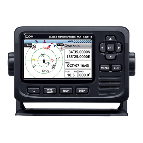
Icom MA-500TR User manual

INSTRUCTION MANUAL
New2001
CLASS B AIS TRANSPONDER
MA-500TR
This device complies with Part 15 of the FCC Rules. Operation is
subject to the condition that this device does not cause harmful
interference.

i
New2001
i
Thank you for choosing this Icom product. This product is de-
signed and built with Icom’s state of the art technology and
craftsmanship. With proper care this product should provide
you with years of trouble-free operation.
IMPORTANT
READ ALL INSTRUCTIONS carefully and completely
before using the transponder.
SAVE THIS INSTRUCTION MANUAL — This in-
struction manual contains important operating instructions
for the MA-500TR class bais transponder.
DFEATURES
❍Full dot-matrix display visually shows real-time
vessel traffic information
❍IPX7 waterproof protection
❍3 lines of NMEA0183 Input/Output
❍GPS receiver comes with the MA-500TR
❍Collision-risk management functions
❍Integration with Icom VHF transceivers
*
*
See the leaflet that comes with the transponder for details of the
corresponding transceiver.
EXPLICIT DEFINITIONS
WORD DEFINITION
RWARNING! Personal injury, fire hazard or electric
shock may occur.
CAUTION Equipment damage may occur.
NOTE
If disregarded, inconvenience only. No risk
of personal injury, fire or electric shock.
CLEAN THE TRANSPONDER THOROUGHLY WITH
FRESH WATER after exposure to saltwater, and dry it be-
fore operating. Otherwise, the transponder's keys, switches
and controllers may become unusable, due to salt crystal-
lization.
NOTE: If the transponder’s waterproof protection appears
defective, carefully clean it with a soft, wet (fresh water)
cloth, then, dry it before operating.
The transponder may lose its waterproof protection if the
case or connector is cracked or broken, or the transponder
has been dropped.

Mounting bracket
For the mounting bracket
DC power cable (OPC-2059)
Knob bolts
Screws (5×20)
Flat washers
(M5)
Spring washers
(M5)
NMEA connector cable
(OPC-2014)
ii
New2001
MXG-5000S gps receiver is sold as a set with the MA-500TR.
• The OPC-2014 has 15
leads, numbered 1 to 15.
SUPPLIED ACCESSORIES
MXG-5000S
MXG-5000S (Referred to as Internal GPS)
Cable length: Approx. 10 m (32.8 ft)
• An instruction sheet comes with the MXG-5000S. Please read it
before installing and operating the MXG-5000S.

iii
New2001
RADIO OPERATOR WARNING
WARNING
Icom requires the radio operator to meet the
FCC Requirements for Radio Frequency Expo-
sure. An omnidirectional antenna with gain not
greater than 9 dBi must be mounted a minimum
of 5 meters (measured from the lowest point of
the antenna) vertically above the main deck and
all possible personnel. This is the minimum safe separation
distance estimated to meet all RF exposure compliance re-
quirements. This 5 meter distance is based on the FCC Safe
Maximum Permissible Exposure (MPE) distance of 3 meters
added to the height of an adult (2 meters) and is appropriate
for all vessels.
For watercraft without suitable structures, the antenna must
be mounted so as to maintain a minimum of 1 meter vertically
between the antenna, (measured from the lowest point of the
antenna), to the heads of all persons AND all persons must
stay outside of the 3 meter MPE radius.
Do not transmit with radio and antenna when persons are
within the MPE radius of the antenna, unless such persons
(such as driver or radio operator) are shielded from antenna
field by a grounded metallic barrier. The MPE Radius is the
minimum distance from the antenna axis that person should
maintain in order to avoid RF exposure higher than the allow-
able MPE level set by FCC.
FAILURE TO OBSERVE THESE LIMITS MAY ALLOW
THOSE WITHIN THE MPE RADIUS TO EXPERIENCE RF
RADIATION ABSORPTION WHICH EXCEEDS THE FCC
MAXIMUM PERMISSIBLE EXPOSURE (MPE) LIMIT.
IT IS THE RESPONSIBILITY OF THE RADIO OPERATOR
TO ENSURE THAT THE MAXIMUM PERMISSIBLE EXPO-
SURE LIMITS ARE OBSERVED AT ALL TIMES DURING
RADIO TRANSMISSION. THE RADIO OPERATOR IS TO
ENSURE THAT NO BYSTANDERS COME WITHIN THE
RADIUS OF THE MAXIMUM PERMISSIBLE EXPOSURE
LIMITS.
Determining MPE Radius
THE MAXIMUM PERMISSIBLE EXPOSURE (MPE) RADIUS
HAS BEEN ESTIMATED TO BE A RADIUS OF ABOUT 3M
PER OET BULLETIN 65 OF THE FCC.
THIS ESTIMATE IS MADE ASSUMING THE MAXIMUM
POWER OF THE RADIO AND ANTENNAS WITH A MAXI-
MUM GAIN OF 9dBi ARE USED FOR AVESSEL MOUNTED
SYSTEM.

iv
New2001
1
2
3
4
5
6
7
8
9
10
11
12
13
14
15
16
Installation:
The installation of this equipment should be made in such a
manner as to respect the EC recommended electromagnetic
field exposure limits. (1999/519/EC)
The maximum RF power available from this device is 2 watts.
The antenna should be installed as high as possible for maxi-
mum efficiency and the installation height should be at least
0.4 meters above any accessible position. In the case where
an antenna cannot be installed at a reasonable height, then
the transmitter should neither be continuously operated for
long periods if any person is within a distance of 0.4 meters
of the antenna, nor operated at all if any person is touching
the antenna.
It is recommended that antenna of a maximum gain of 3 dB
are used. If higher gain antenna are required then please
contact your Icom distributor for revised installation recom-
mendations.
Operation:
The exposure to RF electromagnetic field is only applicable
when this device is transmitting. This exposure is naturally re-
duced due to the nature of alternating periods of receiving and
transmitting. Keep your transmissions to the minimum neces-
sary.
INSTALLATION NOTE FCC INFORMATION
This equipment has been tested and found to comply with the
limits for a Class A digital device, pursuant to part 15 of the
FCC Rules. These limits are designed to provide reasonable
protection against harmful interference when the equipment is
operated in a commercial environment.This equipment gener-
ates, uses, and can radiate radio frequency energy and, if not
installed and used in accordance with the instruction manual,
may cause harmful interference to radio communications.
Operation of this equipment in a residential area is likely to
cause harmful interference in which case the user will be re-
quired to correct the interference at his own expense.
Icom, Icom Inc. and Icom logo are registered trademarks of Icom Incorporated
(Japan) in Japan, the United States, the United Kingdom, Germany, France,
Spain, Russia, Australia, New Zealand, and/or other countries.
MarineCommander is a trademark of Icom Incorporated.
All other products or brands are registered trademarks or trademarks of their
respective holders.
Icom is not responsible for the destruction, damage to, or
performance of any Icom or non-Icom equipment, if the
malfunction is because of:
• Force majeure, including, but not limited to, fires, earth-
quakes, storms, floods, lightning, other natural disasters,
disturbances, riots, war, or radioactive contamination.
• The use of Icom transceivers with any equipment that is
not manufactured or approved by Icom.
v
New2001
COUNTRY CODE LIST
• ISO 3166-1
Country Codes Country Codes
1
2
3
4
5
6
7
8
9
10
11
12
13
14
15
16
17
Austria
Belgium
Bulgaria
Croatia
Czech Republic
Cyprus
Denmark
Estonia
Finland
France
Germany
Greece
Hungary
Iceland
Ireland
Italy
Latvia
AT
BE
BG
HR
CZ
CY
DK
EE
FI
FR
DE
GR
HU
IS
IE
IT
LV
18
19
20
21
22
23
24
25
26
27
28
29
30
31
32
33
Liechtenstein
Lithuania
Luxembourg
Malta
Netherlands
Norway
Poland
Portugal
Romania
Slovakia
Slovenia
Spain
Sweden
Switzerland
Turkey
United Kingdom
LI
LT
LU
MT
NL
NO
PL
PT
RO
SK
SI
ES
SE
CH
TR
GB
DISPOSAL
The crossed-out wheeled-bin symbol on your
product, literature, or packaging reminds you that
in the European Union, all electrical and elec-
tronic products, batteries, and accumulators
(rechargeable batteries) must be taken to desig-
nated collection locations at the end of their
working life. Do not dispose of these products as unsorted
municipal waste.
Dispose of them according to the laws in your area.
ABOUT CE AND DOC
Hereby, Icom Inc. declares that the versions of
MA-500TR which have the “CE” symbol on the
product, comply with the essential requirements
of the Radio Equipment Directive, 2014/53/EU,
and the restriction of the use of certain hazardous sub-
stances in electrical and electronic equipment Directive,
2011/65/EU. The full text of the EU declaration of conformity
is available at the following internet address:
http://www.icom.co.jp/world/support

vi
New2001
PRECAUTIONS
RWARNING! NEVER connect the transponder to an
AC outlet. This may pose a fire hazard or result in an electric
shock.
RWARNING! NEVER connect the transponder to a
power source of more than 16 V DC such as a 24 V DC. This
could cause a fire or damage the transponder.
RWARNING! NEVER reverse the DC power cable po-
larity when connecting to a power source.This could damage
the transponder.
RWARNING! NEVER cut the DC power cable between
the DC plug at the back of the transponder and fuse holder. If
an incorrect connection is made after cutting, the transponder
may be damaged.
RWARNING! NEVER operate the transponder during
a lightning storm. It may result in an electric shock, cause a
fire or damage the transponder. Always disconnect the power
source and antenna before a storm.
CAUTION:
NEVER place the
transponder
where normal
operation of the vessel may be hindered or where it could
cause bodily injury.
KEEP the transponder at least 1 m (3.3 ft) away from the
vessel’s magnetic navigation compass.
DO NOT operate or place the transponder in areas with
temperatures below –20°C (–4°F) or above +60°C (+140°F)
or, in areas subject to direct sunlight, such as the dashboard.
DO NOT use harsh solvents such as benzine or alcohol to
clean the transponder, as they will damage the transponder
surfaces. If the transponder becomes dusty or dirty, wipe it
clean with a soft, dry cloth.
BE CAREFUL! The transponder rear panel will become
hot when operating continuously for long periods of time.
Place the transponder in a secure place to avoid inadvertent
use by children.
BE CAREFUL! The transponder meets IPX7* require-
ments for waterproof protection. However, once the tran-
sponder has been dropped, waterproof protection cannot be
guaranteed because of possible damage to the transponder’s
case or the waterproof seal.
* Except for the DC power and cloning cable connectors.
For U.S.A. only
CAUTION: Changes or modifications to this device, not
expressly approved by Icom Inc., could void your authority to
operate this device under FCC regulations.

vii
New2001
TABLE OF CONTENTS
New2001
IMPORTANT ......................................................................... i
EXPLICIT DEFINITIONS....................................................... i
SUPPLIED ACCESSORIES................................................. ii
RADIO OPERATOR WARNING.......................................... iii
INSTALLATION NOTE........................................................ iv
FCC INFORMATION........................................................... iv
ABOUT CE AND DOC.......................................................... v
DISPOSAL............................................................................ v
COUNTRY CODE LIST........................................................ v
PRECAUTIONS................................................................... vi
1 OVERVIEW......................................................................1
2 PANEL DESCRIPTION ...............................................2–6
■Front panel ...................................................................2
■Function display............................................................4
3 PREPARATION.........................................................7–13
■MMSI code setting........................................................7
■Initial setting mode .......................................................9
4 BASIC OPERATION ...............................................14–24
■Turning power ON ......................................................14
■Display backlight and contrast settings ......................15
■Plotter display operation.............................................15
■Target list display operation .......................................16
■Danger list display operation......................................17
■About the detail screen ..............................................17
■Individual DSC call
(Possible only when a transceiver is connected)................24
5 OTHER FUNCTIONS ..............................................25–29
■Message.....................................................................25
■Waypoint ....................................................................26
■Lost target ..................................................................29
6 MENU MODE OPERATION ....................................30–36
■General ......................................................................30
■Menu mode items.......................................................30
7 INSTALLATION AND CONNECTIONS ..................37–44
■Connections ...............................................................37
■Fuse replacement ......................................................40
■About the VHF antenna..............................................40
■Transceiver connection ..............................................41
■Mounting the transponder ..........................................43
■MB-75 installation.......................................................44
8 MAINTENANCE ......................................................45–47
■Troubleshooting .........................................................45
■Error message............................................................46
■Diagnostics.................................................................46
9 SPECIFICATIONS AND OPTION .................................48
■Specifications .............................................................48
■Option.........................................................................48
10 TEMPLATE....................................................................49
11 AtoN CODE AND DESCRIPTION.................................51

1
DABOUT AIS
AIS is an acronym for “Automatic Identification System.”
An AIS transponder is a short range data radio unit, used
primarily for collision-risk management and navigation safety.
It automatically transmits and receives vessel information
such as the vessel name, MMSI code, vessel type, position
data, speed, course, destination and more. Information is ex-
changed among the vessels and/or base stations on the VHF
maritime mobile band. The information helps to identify other
nearby vessels or stations by displaying the received data on
a plotter or a radar screen.
Your vessel
(Class B AIS)
Other vessel
(Class A AIS)
Other vessel
(Class B AIS)
Base Station
Vessel information
DAIS Classes
There are seven types of AIS stations; vessels, base stations,
Aids to Navigation (AtoN), Search and Rescue (SAR), Search
and Rescue Transmitter (AIS-SART), MOB (Man OverBoard)
and EPIRB (Emergency Position Indicating Radio Beacon)-
AIS.
There are two classes of AIS units, which are installed on
vessels; Class A and Class B.
Under the Safety Of Life At Sea (SOLAS) convention, all
SOLAS vessels, as described below, are required to install a
Class A AIS transponder:
• Upwards of 300 gross tonnage engaged on international
voyages.
• Passenger vessels, irrespective of size, engaged on inter-
national voyages.
• Upwards of 500 gross tonnage not engaged on international
voyages.
A Class B AIS transponder is designed to be interoperability
with Class A units, but not to impact the Class A network.
Many commercial vessels, and some leisure craft, not clas-
sified as requiring a Class A unit, choose to install a Class B
unit to avoid accidents at sea.
1
1
OVERVIEW
New2001
1
2
3
4
5
6
7
8
9
10
11
12
13
14
15
16

22
PANEL DESCRIPTION
2
■Front panel
Function display (p. 4)
Speaker
qw e
r
w
e
t
y
io
u
The angle brackets show common or special display op-
erations, as described below:
• <Common> shows the common operation.
• <In the plotter display> shows the plotter display opera-
tion.
• <In the target list display> shows the target list display
operation.
• <In the danger list display> shows the danger list dis-
play operation.
qDISPLAY MODE KEY [DISP MODE]
<Common>
➥Push to switch the display mode between the plotter,
target list and danger list. (pp. 4−6)
➥While in the Menu mode, push to exit it, and return to
the plotter, target list or danger list display which was
selected before you entered the Menu mode.
wLEFT AND RIGHT KEYS [Ω]/[≈]
<Common>
While in the Menu item setting mode, push to select a
menu option. (pp. 31, 35)
<In the plotter display>
➥Push [Ω]to sequentially select each AIS target icon far-
thest from your vessel (or waypoint, if it is set; see page
26 for setting detail).
(p. 15)
➥Push [≈]to sequentially select each AIS target icon
closest to your vessel (or waypoint, if it is set; see page
26 for setting detail).
(p. 15)
•
A target box will appear around the selected target or waypoint
icon.
<In the danger list display>
➥Push [Ω]to sort the AIS target data by CPA (Closest
Point of Approach).
(p. 17)
➥Push [≈]to sort the AIS target data by TCPA (Time to
CPA).
(p. 17)

33
2
PANEL DESCRIPTION
New2001
eUP AND DOWN KEYS [∫]/[√]
<Common>
➥While in the Menu mode, push to select a menu item.
(pp. 9, 30)
➥Push to select a voice channel in the voice channel se-
lection screen.
(p. 24)
<In the plotter display>
Push to select the display range.
(p. 15)
<In the target or danger list display>
Push to select an AIS target in the target or danger list
display.
(pp. 16, 17)
rENTER KEY [ENT]
<Common>
➥Push to display the detail screen of the selected AIS
target. (pp. 15−17)
➥Push to save the input data. (pp. 8, 10, 15)
➥Push to enter the Menu item setting mode.
(pp. 9, 30)
➥While in the Menu item setting mode, push to select a
menu option.
(pp. 11, 12, 16, 31, 34
−36
)
➥While searching for a GPS satellite, push [ENT] to dis-
play the GPS information screen. (p. 14, 33)
tMENU KEY [MENU]
<Common>
➥Push to enter the Menu mode. (pp. 9, 30)
➥While in the Menu mode, push to exit it, and return to
the plotter, target list or danger list display which was
selected before you entered the Menu mode.
yCLEAR KEY [CLEAR]
<Common>
➥Push to cancel the entered function, or return to the pre-
vious screen. (pp. 10, 13, 25)
➥While in the Menu mode, push to exit it, and return to the
previous screen. (pp. 9, 30)
➥Push to stop an alarm. (pp. 15−17)
uDSC KEY [DSC]
<Common>
➥When the AIS target is selected, or the detail screen is
displayed, push to display the voice channel selection
screen. (p. 24)
➥After selecting the voice channel, push to transmit an
Individual DSC call to the selected AIS target. (p. 24)
This function is available only when a transceiver is con-
nected to the transponder. (p. 41)
iPOWER/BRILL KEY [POWER•BRILL]
<Common>
➥
Hold down for 1 second to turn the power ON or OFF.
(p. 14)
•
After turning ON the power, the opening screen will appear.
➥Push to show the display backlight and contrast adjust-
ing screen. (p. 15)
oMAN OVERBOAT KEY [MOB]
<Common>
Hold down for 1 second to set the waypoint.
(p. 27)
• The MOB alarm sounds, and a flag icon appears on your current
position.
2

1-1-32 Kamiminami, Hirano-ku, Osaka 547-0003, Japan
New2001
A6860D-1EX-8
Printed in Japan
©2011–2018 Icom Inc.
Printed on recycled paper with soy ink.
Other manuals for MA-500TR
1
Table of contents
Other Icom Marine Radio manuals

Icom
Icom IC-M802 Quick start guide

Icom
Icom MA-510TR User manual

Icom
Icom IC-M80 User manual

Icom
Icom IC-M501 Quick start guide

Icom
Icom IC-M802 Instruction Manual

Icom
Icom MA-500TR User manual

Icom
Icom IC-M80 User manual

Icom
Icom IC-M25 User manual

Icom
Icom MarineComander MXS-5000 User manual

Icom
Icom IC-M802 Installation manual