RT-1000 Multichannel - General System Description
RHOTHETA Page 4 of 23 User Manual
1 General Information
The RT-1000 Multichannel system is a direction finder (DF), which is designed for air traffic
control (ATC) and for vessel traffic service (VTS) applications. The system is based on the
very successful standard RT-1000 A and RT-1000 C Doppler direction finder, whose main
components are applied in the multichannel system. In applications where more than 2
simultaneously bearing channels are required, the RT-1000 Multichannel is the solution with
best cost-performance ratio. The flexible design enables system adaptation to almost all
applications. It is realised by using a couple of different standard components, which may be
combined and configured individually. The system can cover up to 24 simultaneous DF-
Channels. The software “DF-Commander” may display the bearing information and control
the system. Through various user interfaces, the DF can be integrated in other systems.
Note:
The RT-1000 Multichannel is not to be used as a voice communication receiver for
aeronautical mobile communication services.
Note:
The DF channels typically will be connected to a display system (e.g. PC software) through a
data network. The maximum reaction time between the start of a signal reception and
completed output of averaged bearing values is 260 ms. This value has to be taken into
account for network transfer and display of bearing data to maintain the 500 ms delay limit
defined by DF certification rules.
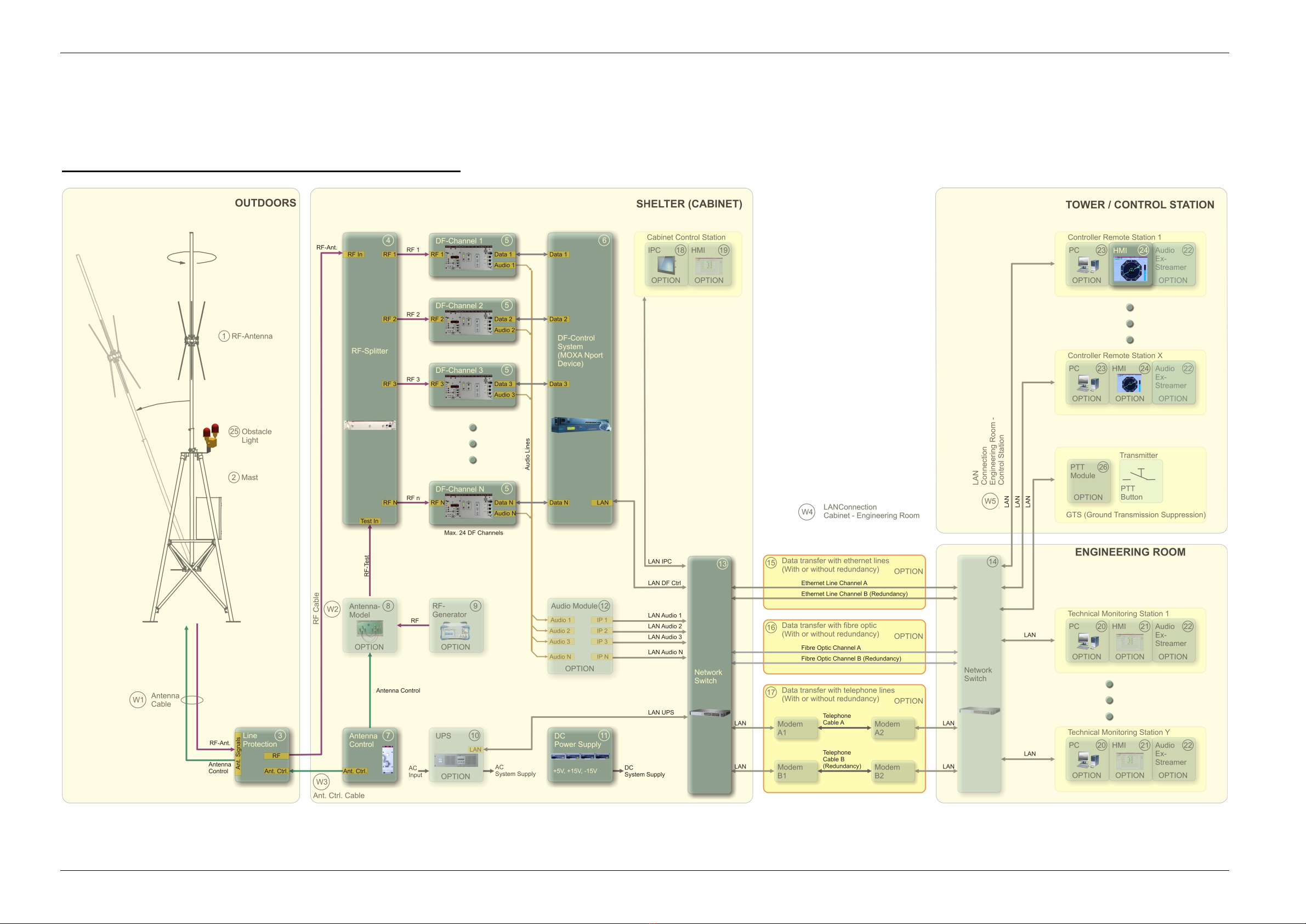
2 System Block Diagram
The RT-1000 Multichannel system is separated in three main parts. The antenna inclusive the
line protection box is installed outdoors. The antenna mast allows the changing of azimuth of
the antenna in exact 10° steps which provides a very convenient testing of the direction finder
only from one position on the field. Furthermore the mast provides a tilting mechanism which
is also very useful for the antenna installation, cleaning and maintenance issues.
The antenna is connected to the shelter with a coaxial cable for receiving the RF-Signal and
the cable for antenna control which conducts the necessary signals to provide the Doppler
modulation.
Further processing of RF-Signal occurs in the shelter inside the DF-Cabinet. First, the RF-
Signal is distributed to all installed DF-Channels by the RF-Splitter. Then DF-Channels
undertake the real signal processing. As an output, every DF-Channel provides an already
computed bearing data via the RS-232 protocol. This data is collected by a MOXA Nport
device, which actually represents the DF Control System, and transmitted via LAN to different
remote stations.
Remote stations represent in general a PC with HMI-Software “DF-Commander”, which not
only provides the visualizing of bearing, but also have the possibility to monitor the function of
all DF-Channels connected.
Remote stations can be integrated in a control tower, engineering room and in the cabinet
with different options of “DF-Commander”. If the transmission of audio is required, the