Digiterm COMFORT-4 ECO User manual

COMFORT-4 ECO
Therapy chair
User Manual
V6.1 EN
U.S. Distribution Partner for:

COMFORT-4 ECO
Version 6.1 EN 1 01.04.2016.
Contents
1. Symbols used in the User Manual and on the chair ................................................ 2
2. Function of the chair................................................................................................... 3
3. Putting in operation.................................................................................................... 4
4. Operating the chair..................................................................................................... 8
4.1. Armrest adjustment.............................................................................................................8
4.2. Use of the handset..............................................................................................................8
4.3. Setting the footrest manually...............................................................................................11
4.4. Setting the motorised footrest (*).........................................................................................11
4.5 Comfort-T2 multifunctional table (*)......................................................................................11
4.6 Infusion bottle holder (*).......................................................................................................11
4.7 Reading lamp (*) ..................................................................................................................11
4.8 Transparent protecting plastic cover for legrest and footrest (*) ...........................................12
4.9 Paper roll holder (*)..............................................................................................................12
4.10 Washable net bag (*) .........................................................................................................12
4.11 Stainless steel armrest protection (*)..................................................................................13
4.12 Central brake (*).................................................................................................................13
4.13 Battery unit (*) ....................................................................................................................13
5. Safe operation of the chair......................................................................................... 14
6. Disinfections and cleaning......................................................................................... 16
7. Maintenance and troubleshooting............................................................................. 17
7.1. Routine maintenance ..........................................................................................................17
7.2. Checking the electronic control ...........................................................................................17
8. Technical data............................................................................................................. 18
8.1. Transport and storage conditions........................................................................................19
8.2. Operating conditions ...........................................................................................................19
8.3 EMC requirements ...............................................................................................................19
8.4. Standards applied ...............................................................................................................21
8.5. Recycling of used parts and special waste disposal............................................................21
9. Periodic technical safety inspection
9.1 Check List for inspection
9.2 Protective earth conductor resistance measurement
10. Spare parts list order form
11. Spare parts list
(*) depending on construction

COMFORT-4 ECO
Version 6.1 EN 2 01.04.2016.
The characteristics and operation of the chair have to be known in order to benefit
from its advantages. Therefore please read the User Manual, particularly the sections
entitled Putting in operation and Safe operation of the chair before use.
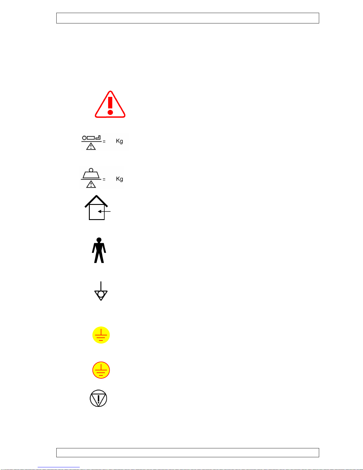
1. Symbols used in the operating instructions and on the chair
This symbol marks information, which is relevant for the
safety and must be observed.
Maximum patient weight
Safe working load
For inside use only.
Degree of protection against electric shock type B
applied part
Equipotential connector
Measuring earth point
Protecting network
Emergency STOP (*)

COMFORT-4 ECO
Version 6.1 EN 3 01.04.2016.
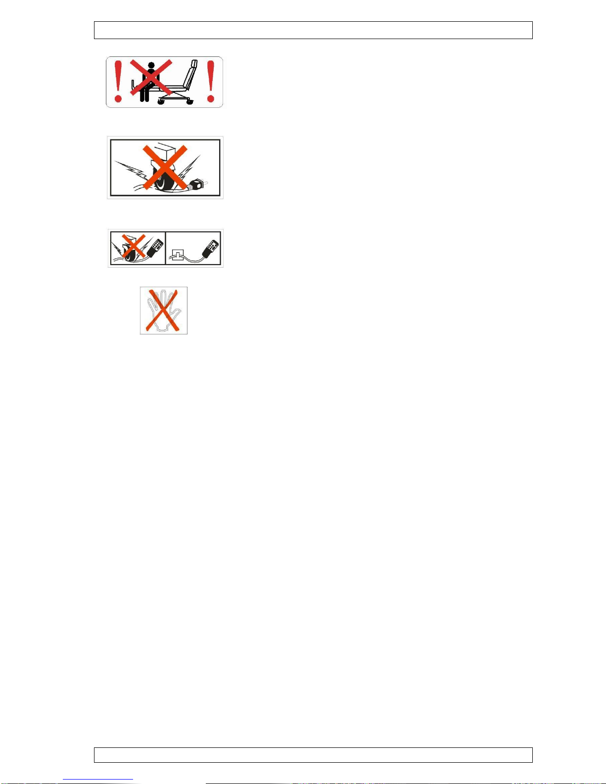
Please do not sit to the legrest!
Do not drive onto the mains cable!
Do not drive onto the handset cable!
Do not touch it!
(*) depending on construction
2. Function of the chair
The chair has been designed and constructed primarily for patient medical
treatment, for example hemodialysis, chemotherapy, pre and post-surgical, etc..
With the help of the handset the segments of the therapy chair can be adjusted
to any desired position that makes treatment comfortable for the patient.
Patient population:
Age: from child to old age
Weight: up to 200 kg or 440 lbs.
Patient state: alert and aware

COMFORT-4 ECO
Version 6.1 EN 4 01.04.2016.
3. Putting in operation
●Before commissioning the chair, remove the packaging and protective
plastic wrap.
●The type of chair (and options) is marked on the packaging and the list of
accessories is included in the documentation.
Note! Please check that the chair accessories (remote control
handset, armrest strap and headrest pillow) are present and
complete.
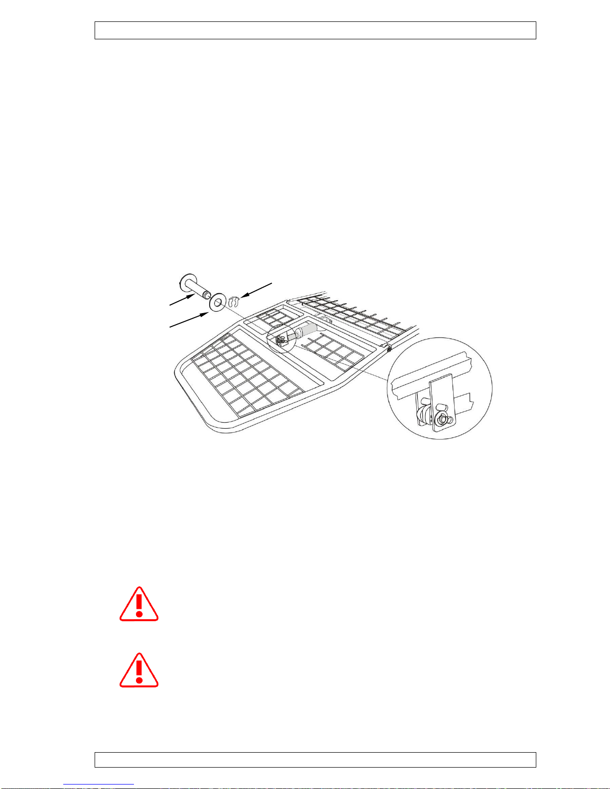
•The motor actuating rod of the legrest is to be connected to the legrest
frame using the pin supplied, according to the illustration. Secure the pin
using the washer and fixing ring. (Figure 1)
Figure 1
●Check whether the handset connection plug is appropriately inserted into
proper connector of electronic control unit (Figure 6/a; 6/b) found under the
seat.
●Check the local mains voltage against the value indicated on the data plate
of the chair before use. If the voltage matches insert the electrical plug into
a mains outlet.
Before switching the chair on, it should be checked whether
condensation (possible with a temperature change) is present on
any electrical components. If there is condensation, then the chair
has to be allowed to reach room temperature.
The control box does not work without closing plug, that should be
connected tightly into this socket (Figure 6/a; 6/b)
pin
fixing ring
washer

COMFORT-4 ECO
Version 6.1 EN 5 01.04.2016.
Attaching the upholstery:
Using the handset, adjust the chair in such a way that the legrest is in line
with the seat plate and the backrest is vertical (Figure 2). This is the easiest
position in which to attach the upholstery.
There are two straps on the back of the upholstery. These have to be
pulled onto the frame (Figure 3, Figure 4).
With the velcro straps found on the two sides of the sitting part of the
upholstery, secure the upholstery to the frame (Figure 5).
Figure 2
Figure 3
Figure 4
Figure 5

COMFORT-4 ECO
Version 6.1 EN 6 01.04.2016.
Attach the headrest pillow to the backrest with the velcro straps. Secure the
armrest strap included in the accessories to the armrest. The armrest strap
is used to position the remote control handset.
●Check whether the motors work properly with the help of the handset.
●Position the chair such that sufficient space is available to enable
unhindered adjustment of the chair in any position and access from all
sides.
Check whether the power or the handset cable is not stretched or
ends up under the wheels or another object while operating the
chair.
(*) depending on construction
Closing plug
Reading lamp
connector (*)
Handset connector
Motor connectors
(In case of less Motors
are connected end cap
must be connected)
Battery unit connector (*)
(In case of no Battery unit
end cap must be
connected)
Figure 6/a
Control box without options
(Basic version)
Power cable

COMFORT-4 ECO
Version 6.1 EN 7 01.04.2016.
(*) depending on construction
Handset connector (*)
(in case of 5 motors)
OR
Connection cable
between the slave
control unit and
junction box (*)
End cap
Connection cable
between the main and
slave control unit (*)
OR
Connection cable
between the main control
unit and junction box (*)
Reading lamp connector (*)
Power cable
Closing plug
OR
Emergency Stop
Switch connector
Handset connector
(in case of optional
Trendelenburg foot-
switch)
Motor connectors
(In case of less Motors
are connected end cap
must be connected)
Battery unit
connector (*)
(In case of no
Battery unit end cap
must be connected)
Connection cable
between the main
and
slave control unit
Motor
connector
s
Power supply
connection cable
(24V DC)
Figure 6/b
Control box with options
Motor connector (*)
OR
Power supply for slave
control box (*)
Main control box
Junction box (*)
Slave control
box (*)
Battery unit (*)
Power cable
junction box (*)
(except EU and
GB power cable)

COMFORT-4 ECO
Version 6.1 EN 8 01.04.2016.
4. Operating the chair
4.1 Armrest adjustment
The height of the armrest can be adjusted by pulling the indexing plunger on the
telescoping rail, moving the armrest up or down and then pushing it back again.
By loosening the knurled knob directly under the armrest, the armrest can be
cantilevered and slipped up and down along its longitudinal axis. The distance
between the armrests can be adjusted by rotating the armrest.
The enhanced mobility of the armrests makes it possible to comfortably seat
differently sized patients. Folding the armrest up to the backrest facilitates
entering the chair from the side. (Figure 7)
Figure 7 Telescopic armrest
4.2 Use of the handset
The adjustment of the chair is done by using the handset (Figure 8/a; 8/b). The
chair moves only as long as a button of the handset is depressed. The control of
the chair makes it possible that more than one motor is active at any time.
Depressing any button is signalled by a green LED on the handset.
More than two minutes of uninterrupted pressing of the button
should be avoided!
The chair can be set into the Trendelenburg position from any
position within a very short space of time by pressing the red
button on the handset.

COMFORT-4 ECO
Version 6.1 EN 9 01.04.2016.
Remote control handset
Figure 8/a
BED position
Backrest up
LED indicates
button pressing
Backrest down
Seat tilt down
Seat tilt up
Legrest down
Legrest up
Seat height down
Seat height up
TRB
Head-down position
ENTRY/LEAVE
ENTRY / LEAVE position

COMFORT-4 ECO
Version 6.1 EN 10 01.04.2016.
BED position
Remote control handset (*)
(if the chair is equipped with motorised footrest adjustment and Battery
option)
Figure 8/b
(*) depending on construction
LED indicates
button pressing
Backrest up
Backrest down
Seat tilt down
Seat tilt up
Legrest down
Legrest up
Seat height down
Seat height up
Footrest down
Footrest up
LED indicates
battery charging (*)
OR
Power on (*)
ENTRY / LEAVE position
ENTRY/LEAVE
TRB
Head-down position

COMFORT-4 ECO
Version 6.1 EN 11 01.04.2016.
4.3 Setting the footrest manually (*)
The position of the footrest can be modified in length. The footrest should be
held to prevent it from slipping, then by loosening the knurled knob on the left
side the footrest can be adjusted into the desired position and secured by
tightening the knurled knob.
4.4 Setting the motorized footrest (*)
With handset, can be adjusted by keeping pressed the button marked according
to desired direction (Figure 8/b).
4.5 Comfort-T2 Multifunctional table (*)
It can be mounted on either sides of the therapy chair (Figure 9).
4.6 Infusion bottle holder (*)
It can be installed onto either sides of therapy chair
and the height of bottle holder is adjustable (Figure 10).
4.7 Reading lamp (*)
The lamp can be switched on and off and dim the light by touch switch on head of the
light. Functions: - quick touch by finger: switch on or off the light (Figure 11a).
- long touch by finger: dim or bright the light (Figure 11b).
4
.
8
Attention: support is not allowed to be rotated fully
around because cables might be damaged!
Figure 11a
Figure 10
Infusion bottle holder
Figure 9
Comfort-T2 Multifunctional table
Figure 11b

COMFORT-4 ECO
Version 6.1 EN 12 01.04.2016.
4.8 Transparent protecting plastic cover for legrest and footrest (*)
The plastic cover is attached by velcro straps onto upholstered legrest and
footrest. Removable for easy disinfection and cleaning. (Figure 12;13)
4.9 Paper roll holder (*)
4.10 Washable net bag (*)
Figure 13
Transparent protecting plastic
cover for the legrest
Figure 12
Transparent protecting plastic
cover for the footrest
Figure 14
Paper roll holder
Figure 15
Washable net bag
The paper roll holder holds and dispenses paper
that helps protect upholstery against dirt, blood and
fluids. etc.
Note: The washable net bag and the paper roll
holder can not be mounted on the chair together!
(Figure 14)
Washable net bag for storing Patient’s belongings.
The washable net bag can be fixed with velcro
straps to the back of the chair, in order to store
mainly small, lighter, personal things. (Figure 15)
Note: The washable net bag and the paper roll
holder can not be mounted on the chair together!

COMFORT-4 ECO
Version 6.1 EN 13 01.04.2016.
4.11 Stainless steel armrest protection (*)
4.12 Central brake (*)
The central brake can be simply
locked to fix the chair.
4.13 Battery unit (*)
The chair is equipped with a Battery unit to ensure the operation of chair during
power failure assuring the patient’s comfort. In this case
the handset operates,
the Trendelenburg foot-switches(*) on the bottom frame operate further on
from battery,
The battery charge is indicated by CHARGE LED on the handset (Figure 8/b).
If the yellow CHARGE LED on the handset is lighting continuously the battery
unit is charged. If the yellow CHARGE LED is flashing the battery unit is
charging.
Note! If chair is not equipped with optional battery unit the yellow
CHARGE LED will light continuously in order to indicate power
on.
In case of power failure use the electronic adjustments only for Emergency or
exiting the chair in order to save battery capacity.
(*) depending on construction
Figure 16
Stainless steel armrest protection
To protect the upholstered armrest against damage.
Note: Fits for TILT-UP ARMREST WITH HEIGHT AND
LONGITUDINAL ADJUSTMENT only. (Figure 16)
Figure 17
Central brake

COMFORT-4 ECO
Version 6.1 EN 14 01.04.2016.
Note! In case of battery back-up operation depressing any button
of the handset is signaled by a short sound!
After 2 minutes of continuous battery operation the battery should
be charged. Do not connect the battery onto external charge
device.
5. Safe operation of the chair
Always check whether the power and the handset cable are
intact before switching the unit on.
If the chair is equipped with EMERGENCY-STOP switch(*):
In case of emergency press the EMERGENCY-STOP switch,
(signed by red label, see Figure 18) to prevent the chair’s
unintended movement and stop the operation of the handset.
Attention! There is electrical shock hazard due to the
EMERGENCY-STOP button could not provide disjunction of the
chair from the main voltage!
After stopping the reason of the emergency, the chair can be
put into action by turning off the EMERGENCY-STOP switch in
the direction of the arrows which can be seen on the red head.
Attention! Do not use the EMERGENCY-STOP button for
switching off the main voltage, because there is electrical
shock hazard due to the EMERGENCY-STOP button could not
provide disjunction of the chair from the main voltage!
(*) depending on construction
If the chair is NOT equipped with EMERGENCY-STOP switch(*):
In case of emergency, disconnect the chair’s power plug and
the battery plug(*) from control unit in order to shut off the
chair. The power plug and battery plug(*) must always be
accessible during operations so that it is possible to shut down
the chair at any time.
Figure 18
EMERGENCY-STOP switch (*)

COMFORT-4 ECO
Version 6.1 EN 15 01.04.2016.
For a long working life and in order to guarantee user safety, we recommend that
the following points be observed:
●Position the chair in such a way that it is accessible from all sides and does
not touch walls or other equipment objects when fully extended.
Not keeping safety distances around the chair during backrest adjustment
could result in the chair backrest being driven into the wall behind the chair, this
may cause additional dynamic overload on the backrest of the chair and lead to
pivot bolt damage.
The below picture makes the installation instructions evident:
Please keep the prescribed safety distances around the chair in
order to avoid any damages of the frame!
The Manufacturer shall not take responsibility for any
consequences of misplacement and abnormal use.
●Check whether the brakes are applied on the casters or the central
brake(*). The brakes should always be locked unless the chair is being
relocated. Otherwise, there is a risk of accidents.
●The therapy chair should always be entered from the side with the armrest
folded up. Make sure the armrest is not overloaded or damage may result.
●The chair should not be entered or exited over the legrest, because
stepping on the footrest or the legrest can cause the chair to tip over or
injury or damage may result.
●Do not sit onto the backrest when it is folded back, because the chair can
tip over.
●Prevent the power cable from being damaged, because a damaged cable
can cause fire or electric shock:
-the power cable should not end up under the therapy chair wheels or
another heavy object,
Figure 9 Expected safe operational environment

COMFORT-4 ECO
Version 6.1 EN 16 01.04.2016.
-don’t leave the power cable near a source of heat, for example a heater,
-when pulling it out of the outlet hold the plug not the cable.
Do not open the cover of the control box, because the ingress
protection (IP) can not be set up again and voids the warranty!
A technical safety examination, as described in the attached
check list in Chapter 9, should be performed after every repair,
and on a two year basis. Please find the yellow label on the
chair’s frame to see the date of next safety inspection. Copy the
check list and fill it out!
6. Disinfection and cleaning
6.1 Disinfection
The materials used for the chair (plastics, artificial leather and colours) are
resistant to the disinfectant products in common use in hospitals. The below matrix
shows which disinfectants are recommended, conditionally recommended or not
recommended for disinfecting upholstery (a solution of up to10% bleach and water
may be used)
- Recommended disinfectants.
- Conditionally recommended disinfectants. Disinfectants should be tested beforehand on a hidden section of
the material. If possible, use diluted and do not allow them to act for a prolonged period.
- Not recommended disinfectants.

COMFORT-4 ECO
Version 6.1 EN 17 01.04.2016.
6.2 Cleaning
First clean on a daily basis the upholstery with warm water and mild soap using
damp cloth. Regular and meticulous cleaning of the upholstery with water in
addition to a mild soap can prevent hardening and embrittlement of the
upholstered parts from such a materials like detergent, sweat, skin oils, hair spray,
hand creams and similar things may affect the leather during treatment.
Avoid ingress of liquid or disinfectant into the electronic control box,
motors and remote control handset. Cleaning of the mechanical parts
(motor actuating rods, bolts and joints) should only be done with a
damp cloth. Abrasive cleaners should not be used and power washing
should not be done.
7. Maintenance and troubleshooting
7.1 Routine maintenance
The following inspections and maintenance work should be done in every two
years with the Technical Safety Inspection (find the check list in chapter 9):
●The hinges and joints of the legrest, backrest and armrest should be
inspected.
●The knurled knob of the armrest should be inspected.
●The wheels should be checked to see whether they are securely fastened
to the frame.
●The slip surface of the footrest should be thinly greased.
●If the knurled knobs or the mechanical parts of the armrests are damaged,
they should be repaired immediately or exchanged.
●Check upholstery for damage.
7.2 Checking the electronic control
Damaged keypad membranes on the handset are to be replaced immediately to
avoid further damage (short circuits caused by liquids entering the handset).
If the chair is connected to the mains but it cannot be operated by use of
handset, then check whether the mains voltage is appropriate.
If the mains voltage is appropriate but operation cannot be realized by keeping
pressed any button please change the handset.
If moving is still not working change the control unit.
If any motor cannot be operated, exchange the defective motor’s plug with a
working one by unplugging wrong motor’s plug from its original socket and
connect it to the neighbouring socket that operates properly with its own motor.
If this motor works in this socket it means there is no trouble with the motor.
Then please check electronic control unit and handset.

COMFORT-4 ECO
Version 6.1 EN 18 01.04.2016.
If you change a fuse or do checking or repairing inside the
electronic control box, the mains plug must be disconnected
from the wall-socket and pull the plug of battery back-up unit
out of the control box which provides total isolation of the chair
from the main voltage.
8. Technical data
Safe working load: 225 kg (495 lbs)
Maximum patient weight: 200 kg (440 lbs)
Horizontal surface length: 210 cm (82.5”)
Chair surface width: 60 cm (23.5”)
Seat height (to top of frame): 47 - 70 cm (18.5” –27.5”)
Distance between telescopic armrests(*): 48 - 60 cm (19” – 23.5”)
Distance between ball-jointed armrests(*): 54 cm (21.25”)
Frame colour: white (RAL9001)
Upholstery colour: light grey or any selected colour
Weight: 80 kg (175 lbs)
Angular range of the backrest: 800
Angular range of the seat: 350
Angular range of the legrest: 300
Footrest adjustment range: 29 cm (11.5”)
Mains voltage: 100V-240V, 50/60 Hz
Peak electric current admittance: max. 4A
Protection class against electric shock: class I
Degree of protection against electric shock: Type B
Degree of protection against water ingress: Protected against splashing water
/IPX6/
Usage protection class: Not to be used in the presence of
flammable anaesthetic gas-air,
anaesthetic gas-oxygen or
anaesthetic gas-nitrous oxide
Operation mode: continuous operation in addition to
periodic loads
After a maximum of two minutes of continuous operation of the
motors, an 18-minute pause must be observed.
Fuses used in the apparatus:
Circuit board 1xT2.5A/250V
1xT6.3A/250V
Reading lamp (LED) 1xT2.5A/250V

COMFORT-4 ECO
Version 6.1 EN 19 01.04.2016.
8.1 Transport and storage conditions
Temperature range: -10 … + 50 0C (14° - 122°)
Relative humidity: max. 80 %
The equipment and its packaging has to be protected from moisture. The top of
the factory cardboard packaging may not be loaded. The equipment
packaged on the wooden rack in the cardboard box may not be tilted from the
horizontal position, which is marked on the box, while storing or moving it.
8.2 Operating conditions
Temperature: +10 … + 40 0C (50° - 104°)
Relative humidity: max. 80 %
(*) depending on construction
8.3 EMC requirements
Installation and operation of the Comfort-4 Eco should be in accordance with the
EMC requirements of tables 1-4.
Table 1
Guidance and manufacturer’s declaration –electromagnetic emissions
The Comfort-4 Eco is intended for use in the electromagnetic environment specified below. The customer or the
user of the Comfort-4 Eco should assure that it is used in such an environment.
Emission test
Compliance
Electromagnetic environment - guidance
RF emissions CISPR 11
Group 1
The Comfort-4 Eco uses RF energy only for its internal
function. Therefore, its RF emissions are very low and are
not likely to cause any interface in nearby electronic
equipment.
RF emissions CISPR 11
Class B
The Comfort-4 Eco is suitable for in all establishments other
than domestic and those directly connected to the public
low-voltage power supply network that supplies buildings
used for domestic purposes.
Harmonic emissions IEC 61000-3-2
Class D
Voltage fluctuations / flicker
emissions IEC 61000-3-3
Applicable
Table 2
Guidance and manufacturer’s declaration –electromagnetic emissions
The Comfort-4 Eco is intended for use in the electromagnetic environment specified below. The customer or the
user of the Comfort-4 Eco should assure that it is used in such an environment.
Immunity test
IEC 60601-1 test level
Compliance level
Electromagnetic environment -
guidance
Electrostatic discharge
(ESD)
IEC 61000-4-2
± 6 kV contact
± 8 kV air
± 6 kV contact
± 8 kV air
Floors should be wood, concrete or
ceramic tile. If floors are covered
with synthetic materials, the relative
humidity should be at least 30 %.
Electrical fast transient
/ burst IEC 61000-4-4
± 2 kV for power supply
lines
± 1 kV for input/output
lines
± 2 kV for power
supply lines
± 1 kV for input/output
lines
Mains power quality should be that
of a typical commercial or hospital
environment.
Table of contents
Popular Medical Equipment manuals by other brands

Direct Supply
Direct Supply Bolster owner's manual

Durr Dental
Durr Dental XR 24 Pro Installation and operating instructions

Scaleo medical
Scaleo medical Poweo Urban user manual

HAPRO
HAPRO HB404 SUMMER GLOW quick start guide

Steris
Steris truFreeze Setup instructions

LAUNCH TECH
LAUNCH TECH X-431 V user manual

Vitalograph
Vitalograph COMPACT 6600 Instructions for use

Hologic
Hologic Aquilex Instructions for Use and Operator's manual

Ropox
Ropox Vario 40-306 Series User Manual, Mounting instruction

Lowenstein Medical
Lowenstein Medical NV Instructions for use

Medela
Medela BiliBed Instructions for use

WillowWood
WillowWood Alpha Basic Patient instructions