DigiTrak Falcon F1 User manual


DIGITALCONTROLINCORPORATED
ii DigiTrak Falcon F1™ Operator's Manual
403-2520-00-A, printed on 8/11/2017
© 2017 Digital Control Incorporated. All rights reserved.
Trademarks
The Aurora logo, the DCI®logo, Aurora®, DigiTrak®, DigiTrak Falcon®, and Target Steering®are U.S. registered trademarks and
Ball-in-the-Box™, FSeries™, F1™, and SuperCell™ are common law trademarks of Digital Control Incorporated.
Patents
U.S. and foreign patents apply to the product covered by this manual. For details, please visit www.DigiTrak.com/patents.
Limited Warranty
All products manufactured and sold by Digital Control Incorporated (DCI) are subject to the terms of a Limited Warranty. A copy of the
Limited Warranty is included at the end of this manual; it can also be obtained at www.DigiTrak.com.
Important Notice
All statements, technical information, and recommendations related to DCI products are based on information believed to be reliable.
However, DCI does not warrant or guarantee the accuracy or completeness of such information. Before using any DCI product, the
user should determine the suitability of the product for its intended use. All statements herein refer to DCI products as delivered by DCI
for use with horizontal directional drilling in the ordinary course, and do not apply to any user customizations, third-party products, or
any usage of the DCI product outside of the ordinary course. Nothing herein shall constitute a warranty by DCI nor will anything herein
be deemed to modify the terms of DCI’s existing Limited Warranty applicable to all DCI products. DCI may update or correct the
information in this manual from time to time. You may find the most recent version of this manual on DCI's website, www.DigiTrak.com.
Under Service & Support, click Documentation and select from the Manuals drop-down menu.
Compliance Statement
This equipment complies with Part 15 of the Rules of the FCC and with Industry Canada license-exempt RSS standards and with
Australia Class License 2000 for LIPD (low interference potential devices). Operation is subject to the following two conditions: (1) this
equipment may not cause harmful interference, and (2) this equipment must accept any interference received, including interference
that may cause undesired operation. DCI is responsible for FCC compliance in the United States: Digital Control Incorporated, 19625
62nd Ave S, Suite B103, Kent WA 98032; phone 425.251.0559 or 800.288.3610 (US/CA).
Changes or modifications to any DCI equipment not expressly approved and carried out by DCI will void the user’s Limited Warranty
and the FCC’s authorization to operate the equipment.
CE Requirements
DigiTrak receivers are classified as Class 2 radio equipment per the R&TTE Directive and may not be legal to operate or
require a user license to operate in some countries. The list of restrictions and the required declarations of conformity
are available on DCI’s website at www.DigiTrak.com. Under Service & Support, click Documentation and select from the CE
Documents drop-down menu.

DIGITALCONTROLINCORPORATED
DigiTrak Falcon F1™ Operator's Manual iii
Contact Us
United States
DCI Headquarters
19625 62nd Ave S, Suite B103
Kent, Washington 98032, USA
1.425.251.0559 / 1.800.288.3610
1.425.251.0702 fax
dci@digital-control.com
Australia 2/9 Frinton Street
Southport QLD 4215
61.7.5531.4283
61.7.5531.2617 fax
dci.australia@digital-control.com
China 368 Xingle Road
Huacao Town
Minhang District
Shanghai 201107, P.R.C.
86.21.6432.5186
86.21.6432.5187 传真
dci.china@digital-control.com
Europe Brueckenstraße 2
97828 Marktheidenfeld
Deutschland
49.9391.810.6100
49.9391.810.6109 Fax
dci.europe@digital-control.com
India DTJ 203, DLF Tower B
Jasola District Center
New Delhi 110025
91.11.4507.0444
91.11.4507.0440 fax
dci.india@digital-control.com
Russia Молодогвардейская ул., д.4
стр. 1, офис 5
Москва, Российская Федерация 121467
7.499.281.8177
7.499.281.8166 факс
dci.russia@digital-control.com

DIGITALCONTROLINCORPORATED
iv DigiTrak Falcon F1™ Operator's Manual
Dear Customer,
Thank you for choosing a DigiTrak guidance system. We are proud of the equipment we have been designing
and building in Washington State since 1990. We believe in providing a unique, high-quality product and
standing behind it with world-class customer service and training.
Please take the time to read this entire manual, especially the section on safety. Please also register your
equipment online at access.DigiTrak.com. Or, fill in the product registration card provided with this
equipment and either fax it to us at 253-395-2800 or mail it to DCI headquarters.
Product registration entitles you to free telephone support (in the USA and Canada), notification of product
updates, and helps us provide you with future product upgrade information.
Our Customer Service department is available 24 hours a day, 7 days a week in the U.S. to help with
problems or questions. International contact information is available in this document and on our website.
As the horizontal directional drilling industry grows, we’re keeping our eye on the future to develop equipment
that makes your job faster, easier, and safer. Visit us online any time to see what we’re up to.
We welcome your questions, comments, and ideas.
Digital Control Incorporated
Kent, Washington
2017
Watch our DigiTrak Training Videos at www.youtube.com/dcikent
For system component name and model information, refer to Appendix A on page 60.

DIGITALCONTROLINCORPORATED
DigiTrak Falcon F1™ Operator's Manual v
Table of Contents
Important Safety Instructions 1
General 1
Pre-Drilling Testing 2
Interference 2
Potential Interference Received 2
Potential Interference Generated 2
Battery Pack Storage 3
Equipment Maintenance 3
General Transmitter Care Instructions 3
Getting Started 5
Introduction 5
Using This Manual 6
Powering On 6
Receiver 7
Transmitter 7
Remote Display (FCD) 7
Setup Summary 7
Select Frequency Optimizer 7
Pair with Transmitter 8
Interference Check 8
Calibrate 8
Above Ground Range Check 8
Receiver 9
Overview 9
Trigger Switch 9
Audible Tones 10
Startup Screen 10
Adjusting Screen Contrast 11
Your Remote Display 11
Receiver Menus 12
Frequency Optimizer 12
So I Just Paired, Now What? 16
Power Off 16
Height-Above-Ground (HAG) 16
Turn HAG On 17
Turn HAG Off 17
Set HAG Value 18
Calibration and AGR 18
1-Point Calibration 19
Above Ground Range (AGR) 21
50 Foot Calibration (Optional) 22
Settings 22
Depth Units Menu 23
Pitch Units Menu 23

DIGITALCONTROLINCORPORATED
vi DigiTrak Falcon F1™ Operator's Manual
Roll Offset Menu 23
Transmitter Options Menu 25
System Timer Menu 26
Telemetry Channel Menu 27
Bubble Level 27
Signal Strength Values 28
Target Steering 28
Locating Basics 29
Locating Screens 30
Locate Screen 30
Locate Screen Shortcuts 31
Depth Screen 31
Predicted Depth Screen 32
Depth Screen, Invalid Location 33
Interference 33
What is Interference? 34
Checking for Interference 34
Roll/Pitch Check 35
Suggestions for Dealing with Interference 36
Locate Points (FLP & RLP) and Locate Line (LL) 37
Effects of Depth, Pitch, and Topography on Distance Between FLP and RLP 38
Marking Locate Points 39
Locating the Transmitter 39
Finding the Front Locate Point (FLP) 40
Finding the Locate Line (LL) 41
Finding the RLP to Confirm Transmitter Heading and Position 43
Advanced Locating 45
Tracking “On-the-Fly” 45
Off-Track Locating 46
Target Steering 48
Feasible Target Steering Area 49
Turning Target Steering On and Off 50
Setting the Target Depth 51
Positioning the Receiver as the Target 52
Steering to the Target with the Remote Display 53
Target Steering in Interference Areas 53
Transmitter 54
Batteries and Power On/Off 55
15-inch Transmitters 55
8-inch Transmitters 55
Installing Batteries / Power On (15-inch) 55
Transmitter Battery Strength 56
Transmitter Current Draw Warning 56
Sleep Mode 56
Transmitter Drill Head Requirements 56
Temperature Status and Overheat Indicator 57
Transmitter Temperature Warning Tones 58
Transmitter Overheat Indicator (Temp Dot) 58
Transmitter Warranty Timer 59

DIGITALCONTROLINCORPORATED
DigiTrak Falcon F1™ Operator's Manual vii
AppendixA: System Specifications 60
Power Requirements 60
Environmental Requirements 60
Storage and Shipping Requirements 60
Temperature 60
Packaging 60
Equipment and Battery Disposal 61
Transmitter Pitch Resolution 61
AppendixB: Receiver Screen Symbols 62
AppendixC: Projected Depth Versus Actual Depth and the Fore/Aft Offset 64
AppendixD: Calculating Depth Based on Distance Between FLP and RLP 68
AppendixE: Reference Tables 69
Depth Increase in Inches per 10-foot Rod 69
Depth Increase in Inches per 15-foot Rod 70
WARRANTY

DIGITALCONTROLINCORPORATED
viii DigiTrak Falcon F1™ Operator's Manual
DIGITALCONTROLINCORPORATED
DigiTrak Falcon F1™ Operator's Manual 1
Important Safety Instructions
General
The following warnings relate generally to the operation of DigiTrak®guidance systems. This is not
an exhaustive list. Always operate your DigiTrak guidance system in accordance with the manual
and be aware of interference that may affect efforts to retrieve accurate data with this guidance
system. Failure to do so can be hazardous. If you have any questions about the operation of the
system, please contact DCI Customer Service for assistance.
To prevent potentially dangerous conditions, all operators must read and understand the safety
precautions, warnings, and instructions before using a DigiTrak guidance system.
DigiTrak guidance systems cannot be used to locate utilities.
Failure to use the front and rear locate points technique described in this manual for locating the
transmitter can lead to inaccurate locates.
Serious injury and death as well as substantial property damage can result if underground drilling
equipment makes contact with an underground utility, including natural gas lines, high-voltage
electrical cable, or other utilities.
DCI equipment is not explosion-proof and should never be used near flammable or explosive
substances.
Work slowdowns and cost overruns can occur if drilling operators do not use the drilling or
guidance equipment correctly to obtain proper performance.
Directional drilling operators MUST at all times:
lUnderstand the safe and proper operation of drilling and guidance equipment, including proper grounding
procedures and techniques for identifying and mitigating interference.
lEnsure all underground utilities and all potential sources of interference have been located, exposed, and
accurately marked prior to drilling.
lWear protective safety clothing such as dielectric boots, gloves, hard hats, high-visibility vests, and
safety glasses.
lLocate and track the transmitter in the drill head accurately and correctly during drilling.
lMaintain a minimum distance of 8 in. from the front of the receiver to the user’s torso to ensure
compliance with RF exposure requirements.
lComply with federal, state, and local governmental regulations (such as OSHA).
lFollow all other safety procedures.
Remove the batteries from all system components during shipping and prolonged storage. Failure to do so
may result in battery leakage, which may lead to risk of explosion, health risks, and/or damage.
Store and transport batteries using a suitable protective case that will keep batteries safely isolated from one
another. Failure to do so may result in short circuits, which may lead to hazardous conditions including fire.
See Appendix A for important restrictions on shipping lithium-ion batteries.
Use of this equipment is restricted to internal use at a construction site.

DIGITALCONTROLINCORPORATED
2 DigiTrak Falcon F1™ Operator's Manual
Pre-Drilling Testing
Before each drilling run, test your DigiTrak guidance system with the transmitter inside the drill head to
confirm it is operating properly and providing accurate drill head location and heading information.
During drilling, the depth will not be accurate unless:
lThe receiver has been properly calibrated and the calibration has been checked for accuracy so the
receiver shows the correct depth.
lThe transmitter has been located correctly and accurately and the receiver is directly above the
transmitter in the drill head underground or at the front locate point.
lThe receiver is placed on the ground or held at the correct height-above-ground distance, which has been
set correctly.
Always test calibration after you have stopped drilling for any length of time.
Interference
The Falcon frequency optimizer selects frequencies based on measured active interference at a given point
in time and space. Active interference levels can change with time and location, passive interference (which
the system does not detect) may be present, and performance may vary as a result. Selections by the
frequency optimizer are not a substitute for prudent operator judgment. If performance drops while drilling,
consider using Max Mode.
Potential Interference Received
Interference can cause inaccuracies in the measurement of depth and loss of the transmitter’s pitch, roll, or
heading. Always perform a background noise check using your receiver (locator), as well as a visual
inspection for possible sources of interference, prior to drilling.
A background noise check will not identify all sources of interference, as it can only pick up sources that are
active, not passive. Interference, as well as a partial list of sources of interference, are discussed in the
section Interference on page33.
Never rely on data that does not display quickly and/or remain stable.
If an Adisplays at the bottom left of the roll indicator or frequency optimizer at distances greater than 10 ft.
from the transmitter, attenuation is in effect, indicating the presence of excessive noise that can lead to
inaccurate depth readings. A flashing signal strength indicates the presence of extreme interference; depth
and locate points will not be accurate.
Potential Interference Generated
Because this equipment may generate, use, and radiate radio frequency energy, there is no guarantee that
interference will not occur at a particular location. If this equipment does interfere with radio or television
reception, which can be determined by powering the equipment off and on, try to correct the interference
using one or more of the following measures:
lReorient or relocate the receiving antenna.
lIncrease the separation between the receiver and affected equipment.
lConsult the dealer, DCI, or an experienced radio/TV technician for help.
lConnect the equipment to an outlet on a different circuit.

DIGITALCONTROLINCORPORATED
DigiTrak Falcon F1™ Operator's Manual 3
Battery Pack Storage
If you plan to store the battery packs for any period of time, please follow these guidelines:
lDo not store the battery pack at temperatures greater than 113° F.
lDo not store the battery pack in a fully discharged state.
lDo not store the battery pack in the battery charger.
lDo not store multiple batteries together where their terminals or other loose conductive materials may
contact one another and cause a short circuit.
If a lithium-ion battery pack will be stored for an extended period of time, pre-charge the battery to a charge
level of 30% to 50% (two or three LEDs illuminated on the meter). Do not store the battery pack for more than
one year unless it is periodically recharged to the 30% to 50% level.
Equipment Maintenance
Turn off all equipment when not in use.
Store the equipment in cases, away from extremes of heat, cold, and moisture. Test to confirm proper
operation prior to use.
Clean the glass screens on the receiver and remote display only with a cleaner specifically formulated to not
harm the protective coatings on the glass. If in doubt, use only warm water and a microfiber cloth. Do not use
household or commercial window cleaning products that include chemicals such as ammonia, alcohol, or
any acidic liquid; these cleaners can contain microscopic abrasive granules that will damage the anti-
reflective coating and may cause the display to spot.
Clean equipment cases and housings using only a soft moist cloth and mild detergent.
Do not steam clean or pressure wash.
Inspect the equipment daily and contact DCI if you see any damage or problems. Do not disassemble or
attempt to repair the equipment.
Do not store or ship this equipment with batteries inside. Always remove the batteries from the equipment
before shipping or periods of non-use.
The battery charger provided with your DigiTrak guidance system is designed with adequate safeguards to
protect you from shock and other hazards when used as specified within this document. If you use the
battery charger in a manner not specified by this document, the protection provided may be impaired. Do not
attempt to disassemble the battery charger, it contains no user-serviceable parts. The battery charger shall
not be installed into caravans, recreational vehicles, or similar vehicles.
General Transmitter Care Instructions
Periodically clean the spring and threads inside the battery compartment as well as the spring and threads of
the battery end cap to ensure a proper power connection with the batteries. Use an emery cloth or wire brush
to remove any oxidation that has built up. Be careful not to damage the battery cap O-ring; remove it while
cleaning if necessary. After cleaning, use a conductive lubricant on the battery cap threads to keep it from
binding in the battery compartment.
For better battery performance, all DCI battery-powered transmitters ship with both
a special battery contact spring and a nickel-based anti-seize lubricant on the
battery end cap to aid in electrical contact.

DIGITALCONTROLINCORPORATED
4 DigiTrak Falcon F1™ Operator's Manual
Before use, inspect the battery cap O-ring for damage that may allow water to enter the battery compartment.
Replace the O-ring if the one installed becomes damaged.
Do not use chemicals to clean the transmitter.
Placing tape around the fiberglass tube of the transmitter, if space allows, will keep the fiberglass protected
from most corrosive and abrasive environmental wear. Do not tape over the IR port as this will interfere with
IR communication.
Falcon 15-inch transmitters have a threaded hole (1/4”-20 thread) in the battery cap to allow the use of an
insertion/extraction tool for installing and removing the transmitters in end-load housings. Ensure this hole
remains clear of debris.
Send in the Product Registration Card or register online at access.DigiTrak.com within 90 days of purchase
to enable the warranty on your equipment, including a 3-year/500-hour warranty on your transmitter. Ask your
dealer about our extended 5-year/750-hour transmitter warranty.

DIGITALCONTROLINCORPORATED
DigiTrak Falcon F1™ Operator's Manual 5
Getting Started
Introduction
1. Falcon Compact
Display
2. Receiver
3. Transmitter
4. NiMH battery charger
DigiTrak Falcon F1™ Guidance System
Congratulations on your purchase of the DigiTrak Falcon®F1™, the entry level system of the DigiTrak
Falcon line of guidance systems. Falcon technology represents a significant advancement in helping crews
overcome one of the biggest obstacles to completing their underground drilling projects: active interference.
Falcon F1 provides crews with access to Falcon technology at an entry-level price, and can be upgraded to
the multi-band Falcon F2®for deeper bores in tougher interference environments.
In today’s competitive underground drilling landscape of deeper bores and more challenging jobsites,
interference has emerged as one of the primary obstacles to completing HDD installations on time.
Interference varies from jobsite to jobsite, at different points within the same jobsite, and even with time of
day. After extensive research and testing in some of the most challenging interference environments in the
world, DCI concluded that selecting a transmitter frequency that sidesteps interference is far more effective
at overcoming this obstacle than simply increasing power.
The Falcon approach involves dividing a wide range of frequencies into bands, then selecting the frequencies
that are least susceptible to the interference in each band. Falcon F1 uses a single band (Band 11) that
encompasses frequencies identified as performing best around interference at the highest number of
jobsites. The system is easy to learn and simple to use every day. By following a few easy steps at the
beginning of each pilot bore, you will be ready to drill within minutes.
Competing systems define success in terms of depth and data range. Falcon technology also provides
tremendous range, but that isn’t what makes Falcon great. DCI defines success as enabling crews to
complete the largest number of jobs possible in the shortest periods of time. Falcon technology is designed
around that principle.
The Falcon system comes standard with a receiver, remote display, transmitter, batteries, and battery
charger. The separate operator's manuals for these devices are located on the flash drive that accompanied
your guidance system and also at www.DigiTrak.com.

DIGITALCONTROLINCORPORATED
6 DigiTrak Falcon F1™ Operator's Manual
Using This Manual
This manual is an important tool for you as the operator of a Falcon guidance system. You can find it on the
flash drive that accompanied your system or at www.DigiTrak.com. We encourage you to load it onto your
mobile device and keep it handy so the information you need is always close at hand.
When something is worth a little extra attention, we'll mark it with this handy Notebook icon.
What if I have a question about this topic?
As you read this manual, you may have questions. We've already answered some of them right at
the source in boxes like this. If the topic isn't for you, skip it and read on.
You might need this.
Sometimes it's handy to have some extra information at your fingertips. While it may be
discussed in detail elsewhere in the manual, we've extracted and placed some important data
right where you need it, with a page link if you want to read more.
Go watch some TV.
Subjects with training videos available online will be marked with this icon.
To help find those distant details, the manual includes hyperlinks that will take you right there, like this
example:
Prior to use, the receiver must be paired to and calibrated with the
transmitter.
Calibration and AGR
Page18
Powering On
The regional designation number in the globes on the receiver startup screen and transmitter body
must match. If they don’t, contact your DigiTrak dealer.
Using the trigger.
Click the trigger to move between menu options. Hold briefly and release to make a selection.
Do nothing in a menu for five seconds to return to the Locate screen.

DIGITALCONTROLINCORPORATED
DigiTrak Falcon F1™ Operator's Manual 7
Receiver
1. Install a fully charged battery pack.
2. Power on the receiver by holding the trigger briefly.
3. Click to accept the “Read the manual before using” statement. The
subsequent information screen provides useful information such as
software version and compatible transmitters. Click to advance.
4. First time use: from the Main >Settings menu , set the depth units,
pitch units, and telemetry channel.
Settings
Page22
5. On the Main menu, set the optional Height-Above-Ground . Height-Above-Ground
(HAG)
Page16
Transmitter
Do not power on the transmitter until after running the frequency optimizer on
the receiver (see next section). After that, simply install batteries with the
positive end first and completely fasten the battery cap.
Batteries and Power On/Off
Page55
Remote Display (FCD)
1. Install a fully charged battery pack in the battery compartment.
2. Press the button to turn on the remote display.
3. First time use: from the Main >Settings menu , set the depth units, pitch units, and telemetry
channel. Use the same settings as on the receiver. It is also good practice to use the same system
of units (English or metric) on both devices.
4. Verify data is being received from receiver. If not, verify proper region is set on both devices.
5. If your existing DigiTrak remote display does not have an option forF1 as the receiver, selectF2.
If you are using a different remote display, refer to the separate operator's manual located on the flash drive
that accompanied your guidance system and also at www.DigiTrak.com.
Setup Summary
Getting started with a Falcon F1™ receiver is easy: run the frequency optimizer, walk and scan the bore
path, pair the receiver with the transmitter, calibrate, check Above Ground Range, and check for active
interference. It's all summarized in the following several paragraphs, with links to the details later in this
manual. If you're hungry for the details now, skip to Receiver on page9.
Select Frequency Optimizer
1. With the transmitter off (batteries not installed), take the receiver to the point along the intended
bore that might create the biggest locating challenge, like the deepest point of the bore or where
there is obvious active interference such as a railway crossing, transformer, traffic lights, or power
lines.
2. Power on the receiver and select Frequency Optimizer (FO)
from the Main menu.
Frequency Optimizer
Page12
3. With the FO results active (the Exit button will be flashing), walk the entire intended bore path with
the receiver and note areas of high background noise (active interference). The higher a frequency
band's bar is on the graph, the greater the interference.

DIGITALCONTROLINCORPORATED
8 DigiTrak Falcon F1™ Operator's Manual
Pair with Transmitter
1. On the receiver, click to activate Band 11, then hold briefly to select.
2. Hold the trigger briefly to assign as the Up band.
3. Select Pair (flashing).
4. Insert batteries in the transmitter, positive end first, install the battery cap, and allow several
seconds for the transmitter to fully power on and begin sending data to the receiver. Regardless of
whether the batteries are loaded with the transmitter facing up or down, the transmitter will always
power on in band 11.
5. Align the receiver and transmitter IR ports within two inches of each other and select the check
mark üto pair. A successful pairing is indicated by a beep and a check mark.
Why can't I select other bands?
The Falcon F1 is set to use Band 11 because its range of frequencies provide the best
performance in a variety of different interference environments. Interference varies with time
and location, and no band works perfectly in all conditions. Lower frequency bands tend to
perform well despite passive interference. Middle bands can perform better in deeper bores and
may have longer Target Steering capability. High bands have slightly less signal strength but tend
to offer better performance around active interference such as power lines.
An upgrade path is available to Falcon F1 owners who seek the performance advantages that
come with the availability of the additional bands shown. Ask your dealer about upgrading your
guidance system to Falcon F2, or trading up to a Falcon F5 for even more features like fluid
pressure monitoring and DataLog.
Interference Check
Now that your transmitter is paired with your receiver, walk the bore with both the
receiver and transmitter powered on to check for active interference.
Interference
Page33
Calibrate
Perform a 1-point (1PT) calibration for the newly optimized frequency band in a low-
noise area with the transmitter in a housing. Always calibrate after optimizing
frequencies and pairing with the transmitter.
Calibration
Page18
Above Ground Range Check
Perform an Above Ground Range check on the new optimized frequency band
before drilling. The AGR screen displays automatically after calibration.
AGR
Page21
If the above-ground AGR distance at 50 ft. is not accurate, conduct a 50FT
calibration (which also uses only one point) to improve the accuracy of the above-
ground distance measurement. A 50 ft. calibration is not necessary for drilling.
50FT Calibration
Page22

DIGITALCONTROLINCORPORATED
DigiTrak Falcon F1™ Operator's Manual 9
Receiver
I know what a trigger switch is; can I skip this?Page12
This section is like shaking hands with your Falcon for the first time. If you and your receiver
already have a solid relationship, you can probably jump ahead to Receiver Menus.
1. Screen
2. Front
3. Infrared port
4. Trigger switch
5. Battery tab
6. Battery compartment
7. Serial number
Falcon F1 Receiver – Side and Back Views
Overview
The DigiTrak Falcon F1™ receiver (locator) is a handheld unit used for locating and tracking a Falcon
wideband transmitter. It converts signals from the transmitter to display depth, pitch, roll, temperature, and
battery level, plus sends this information to the remote display on the drill rig.
The receiver and transmitter must meet specific operational requirements for
different global regions. A regional designation number is located on the
receiver’s startup screen. This number must match the one stamped on the
transmitter for proper communication.
Startup Screen
Page10
Prior to use, the receiver must be paired to and calibrated with the transmitter. Calibration
Page18
Trigger Switch
The Falcon receiver has one trigger switch located under the handle for operating the system. Use it to turn
on the receiver, move through menu options, and change the screen view for depth readings. Click to cycle
through options or hold briefly and release to make a selection.
I passed the menu option I want; do I have to keep clicking?
After several seconds of inactivity, the display returns to the Locate screen and you can try
again.
DIGITALCONTROLINCORPORATED
10 DigiTrak Falcon F1™ Operator's Manual
Audible Tones
The Falcon F1 receiver beeps to signal power on/off, confirm menu
changes, and acknowledge the pass/fail status of actions. The receiver
also beeps with transmitter temperature increases.
Transmitter Temperature Warning
Tones
Page58
Two long beeps indicate a problem with the menu option selected and a failure screen will appear until you
click the trigger or remove the battery (in the case of a critical failure). Verify your setup and try the operation
again or contact DCI Customer Service for assistance.
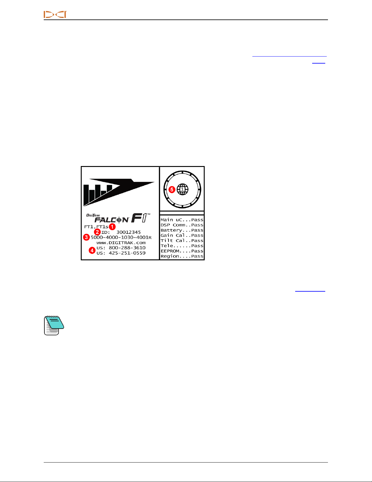
Startup Screen
Insert a charged battery pack. To power on the receiver, click the trigger. After you have read the warning
screen, click again to acknowledge you have read and understand this manual. The receiver displays the
startup screen, which includes the results of several startup tests:
1. Compatible transmitters
2. Receiver ID number
3. Software version
4. Customer service phone
numbers
5. Regional designation number
must match that of
transmitter
Receiver Startup Screen
Click to exit the startup screen. The Falcon F1 receiver proceeds to the
Locate screen.
Locate Screen
Page30
If an item of the self-test fails, a "Fail" warning displays on the startup screen instead of
"Pass". An exclamation mark(!) may also appear in the roll indicator on the Locate screen.
Please contact DCI Customer Service.

DIGITALCONTROLINCORPORATED
DigiTrak Falcon F1™ Operator's Manual 11
Adjusting Screen Contrast
To make the screen lighter or darker, hold the trigger while on the Locate screen with the receiver held
vertical. Release the trigger when the screen contrast reaches the desired level.
The contrast changed way too much; how do I change it back?
Keep holding the trigger; the contrast will adjust completely dark or light, then adjust in the
opposite direction.
Your Remote Display
The Falcon F1 receiver is compatible with the following remote displays:
Remote Display Minimum Software Version Select on Remote Display
Falcon Compact Display - FCD 4.0 Falcon F1, F2
Multi-Function Display - MFD 3.0, F2 compatible F2
F Series Display - FSD all F2
Aurora - AP8, AF8, AF10 all Falcon F1, F2
A remote display that accompanied your Falcon F1 receiver will already be set to communicate with your
receiver.
If you purchased your Falcon receiver by itself, your existing remote display may not include the required
option. If so, contact your regional DCI office or Customer Service for a software upgrade.
The operator's manuals for these remote displays are located on the flash drive that accompanied your
Falcon system and also at www.DigiTrak.com. For an MFD, use the FSD manual.
DIGITALCONTROLINCORPORATED
12 DigiTrak Falcon F1™ Operator's Manual
Receiver Menus
I am already familiar with DigiTrak receiver menus; can I skip this?Page29
If you have used a DigiTrak SE®or F2®receiver, you are well on your way to mastering a
Falcon. Read the next section on the Frequency Optimizer, then skip ahead to Locating Basics.
Come back and visit later as needed for reference. If this is your first DigiTrak, keep reading.
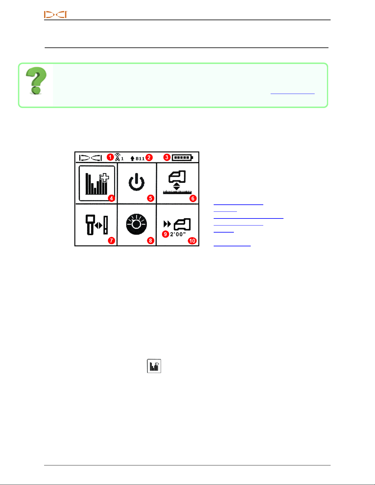
To access the Main menu from the Locate screen, click the trigger. Click repeatedly to move through the
menu, then hold the trigger briefly and release to make a selection. The Frequency Optimizer icon is shown
selected below; holding the trigger briefly would start this feature.
1. Telemetry channel
2. Transmitter band
3. Receiver battery strength
4. Frequency Optimizer
5. Power Off
6. Height-Above-Ground (HAG)
7. Calibration and AGR
8. Settings
9. Target depth
10. Target Steering
Receiver Main Menu
The top of the Main menu displays the telemetry channel, transmitter frequency band, and receiver battery
strength.
The following sections describe the Main menu items in order. Use the links above to jump straight to a
section.
If the Target Steering menu has been programmed with a target depth, it displays below the Target Steering
icon as shown.
If you open the Main menu accidentally, either click through all the options to return to the Locate screen or
wait a few seconds for the menu to time out and return automatically.
Frequency Optimizer
This section addresses Falcon technology's ground-breaking frequency optimizer (FO) feature, which finds
the lowest-noise (optimal) group of frequencies available in Band 11. When the results display in graph form
showing the levels of active interference in each band, choose Band 11, pair, and you're ready to calibrate
and start drilling.
Table of contents
Other DigiTrak Measuring Instrument manuals


Popular Measuring Instrument manuals by other brands


National Instruments
National Instruments PXIe-5667 Getting started guide

Siemens
Siemens ACCESS 9340 Reference manual

Anritsu
Anritsu MS2690A Operation manuals

Hach Ultra
Hach Ultra ORBISPHERE 3625 Operator's manual

Keysight Technologies
Keysight Technologies U1701B quick start guide

Agilent Technologies
Agilent Technologies 4395A Service manual

IMI SENSORS
IMI SENSORS PCB Piezotronics M623C11 Installation and operating manual

elmeasure
elmeasure SL VDC user manual

TSI Instruments
TSI Instruments ALNOR RVA501 Operation and service manual

X-IO
X-IO x-IMU3 user manual

Simrad
Simrad SAL R1a Easy Tank user manual

HART
HART Proline Promag 400 Description of Device Parameters