Blaupunkt DC-S3 User manual

ART. 35/09175-00 PAGINA 1 DI 4
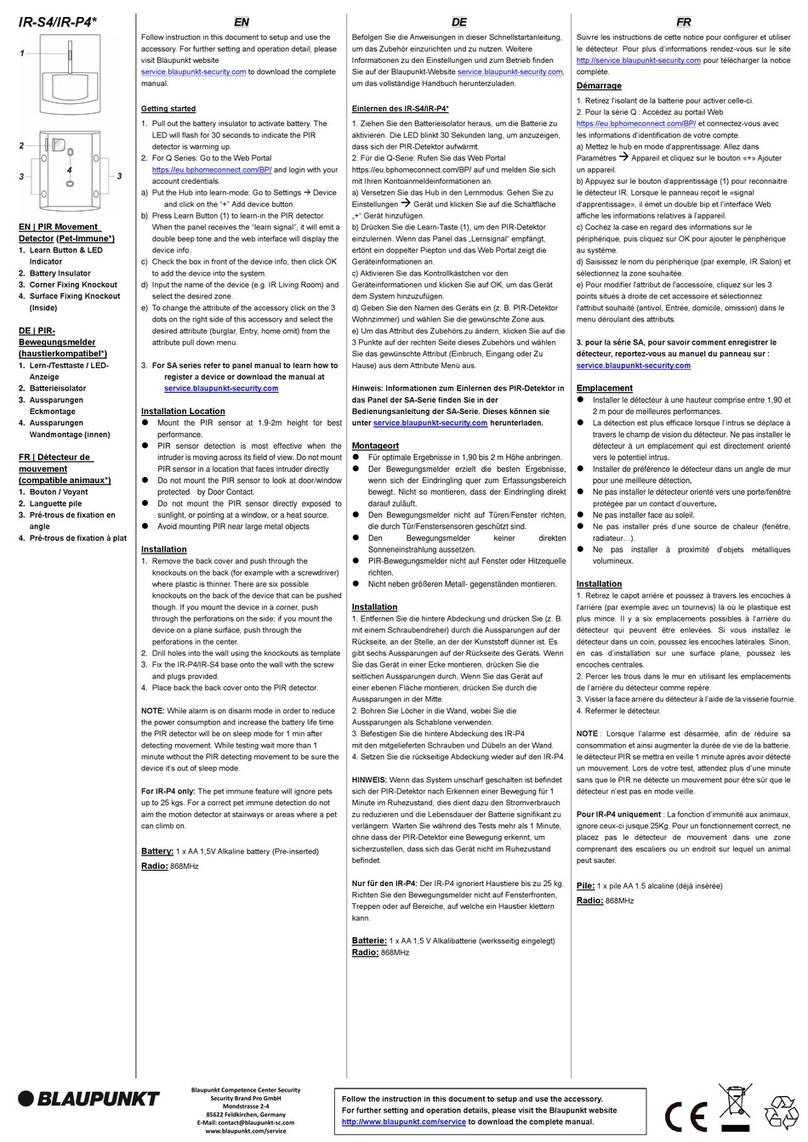
&RQWDWWRSHUSRUWD¿QHVWUD'&6
Descrizione delle parti:
,QGLFDWRUL/('H3XOVDQWH/HDUQ7HVW
Premere il pulsante per trasmettere il segnale di Learn/test e
entrare in modalità test per 3 minuti. La spia LED si accenderà se
un movimento viene rilevato in modalità Test.
2. Fori di montaggio (coperti da coperchio bianco)
,QJUHVVR)LODUH
Collega il terminale a qualsiasi dispositivo Normalmente Chiuso
(N.C)
,QJUHVVR)LODUH
Collega il terminale al sensore tapparella.
,QWHUUXWWRUL-XPSHU
Per le funzioni interruttori Jumper Switch functions, fate riferimento
alla sezione “Impostazione Interruttori Jumper”.
,VRODQWH%DWWHULD
,QWHUUXWWRUH7DPSHU
7DSSRSHUWHUPLQDOLDJJLXQWLYL
6HJQLGLULOHYD]LRQH
10. Magnete
Contenuto della confezione
1 x Contatto porte
[7DVVHOOLHYLWLSHU¿VVDJJLRDPXUR
1 x Biadesivo
1 x Batteria al litio 3V (pre-installata)
Mettere il Pannello di Controllo in modalità di apprendimento
(learning), premere di seguito il tasto Learn per trasmettere il
codice learn. Riferirsi al manuale di istruzioni del pannello di
FRQWUROORSHU¿QDOL]]DUHODSURFHGXUDGLDEELQDPHQWR
4XHVWRVHQVRUHSXzHVVHUHXWLOL]]DWRFRPHFRQWDWWRSRUWH¿QHVWUH
RFRPHWUDVPHWWLWRUHSHUWDSSDUHOOHRTXDOVLDVLVHQVRUH¿ODUH
&RPHFRQWDWWRSRUWH¿QHVWUH posizionate il sensore sul telaio
GHOODSRUWDR¿QHVWUDHLOPDJQHWHVXOODVWHVVD
&RPHWUDVPHWWLWRUHSHUVHQVRUH¿ODUH posizionate il contatto
vicino al sensore da collegare.
1RQSRVL]LRQDWHVXVXSHU¿FLPHWDOOLFKH
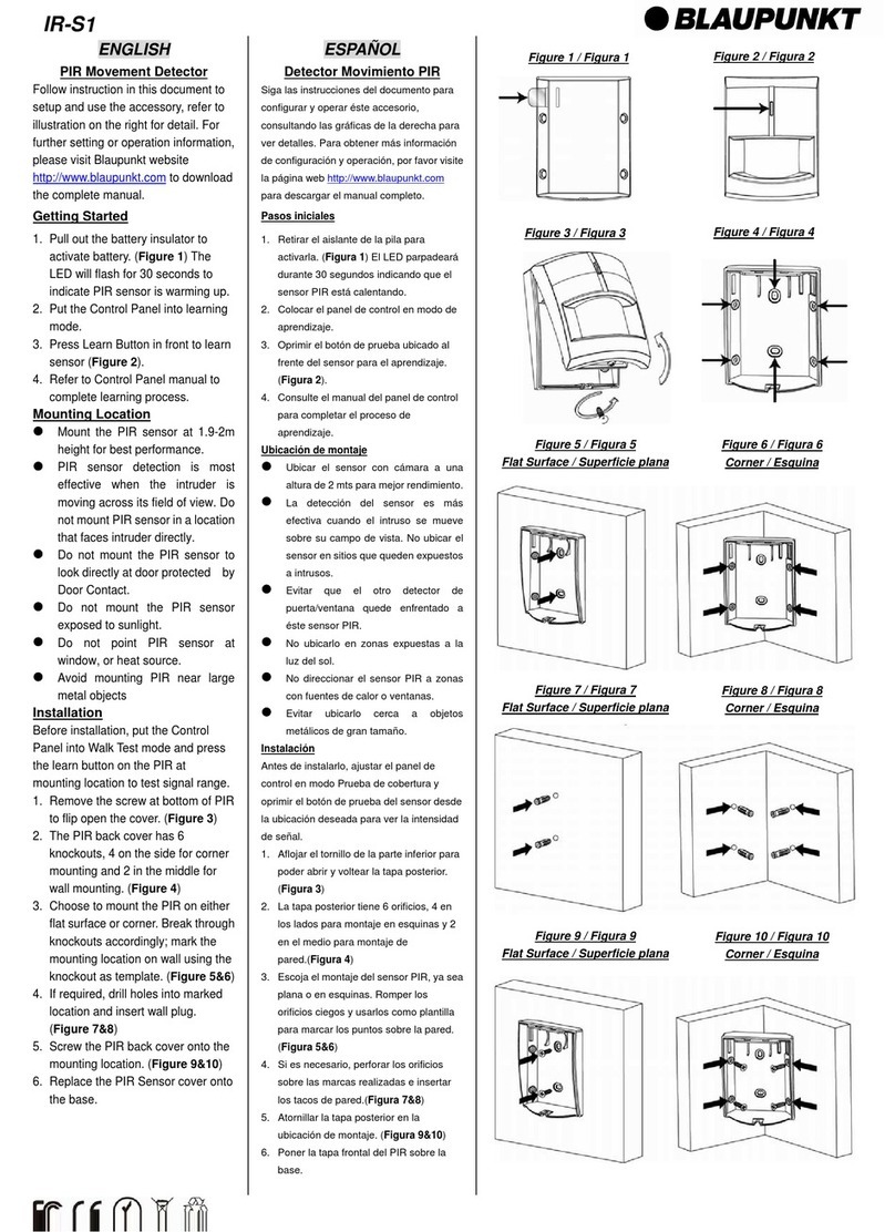
1.5LPXRYHWHLWDSSLELDQFKLFKHULFRSURQRLGXHIRULGLPRQWDJJLR
2.Praticare i fori sul muro utilizzando i fori di montaggio come
dima.
)LVVDWH ODEDVH GHO&RQWDWWR 0DJQHWLFR3RUWD VXOPXUR FRQL
tasselli e viti forniti.
&RPHVHQVRUHSRUWH¿QHVWUH
4. Allineate il magnete al sensore; avvitate il magnete (o utlizzate
LOELDGHVLYRSHU¿VVDUORDOODSRUWDR¿QHVWUD
La distanza tra sensore e magnete QRQGHYHVXSHUDUHLPP
&RPHWUDVPHWWLWRUH
5RPSHWHODFRYHUGLSURWH]LRQHELDQFD
3HUVHQVRUH¿ODUHFROOHJDWHL¿OLGHOVHQVRUHDO:LUH,QSXW
7HUPLQDO6HQVRULDFDEODJJLRPXOWLSORSRVVRQRHVVHUHFROOHJDWL
contemporaneamente creando un circuito chiuso con il contatto.
)LJXUD$
3HUWDSSDUHOODFROOHJDWHL¿OLGHOVHQVRUHDO:LUH,QSXW
Terminal 2.)LJXUD%
8. Riposizionate i cappucci
Porta/Finestra Cornice
Figura A Figura B
Abbinamento
Installazione

ART. 35/09175-00 PAGINA 2 DI 4
Attivazione
Dopo l’attivazione il sensore si attiva nelle seguenti condizioni:
1. Quando la porta si apre e il magnete si allontana dal corpo
principale e si attiva l'interruttore Reed all'interno del rivelatore.
2. Quando un sensore normalmente chiuso (N.C.) collegato al
:LUH,QSXW7HUPLQDOVLDWWLYDDSHUWR
4XDQGRLO¿ORFROOHJDWRGHOODWDSSDUHOODDO:LUH,QSXW7HUPLQDO
é tirato per una distanza impostata.
Fate riferimento al capitolo Jumper Switch Setting per
impostare la distanza di attivazione del sensore tapparella.
Interruttore Tamper
Il sensore è protetto da un interruttore tamper (antimanomissione)
che si attiva se il coperchio viene aperto o manomesso. Durante
l’installazione del sensore, assicurarsi che l’interruttore tamper
sia correttamente compresso contro il pannello frontale, e che
LOFRSHUFKLR IURQWDOH VLD FRUUHWWDPHQWH¿VVDWR FRQ OH YLWL4XDQGR
l’interruttore tamper è attivato invierà un segnale al pannello di
controllo.
Modalità Test
Premere il tasto Test per entrare nella modaliatà Test per un perio-
do di tempo di 3 minuti. In modalità Test, la spia LED si accende
ogni volta che il Contatto Magnetico Porta é attivato.
Indicatore LED
Off Funzionamento normale
On (2 secondi) Se l’interruttore Tamper é attivato
-Rilevatore attivato (porta aperta/Sensore
¿ODUHDWWLYRWDSSDUHOODPRVVDEDWWHULD
scarica, tamper o modalità Test.
Batteria
,O&RQWDWWRXVDXQDEDWWHULDDOOLWLR9$$
Ê DQFKH GRWDWR GHOOD IXQ]LRQH EDWWHULD VFDULFD SHU QRWL¿FDUH DO
SDQQHOORGLFRQWUROORTXDQGRLOOLYHOORGHOOHEDWWHULHpWURSSREDVVR
,Q FDVR GL EDWWHULH VFDULFKH VHJXLUH OD VHJXHQWH SURFHGXUD SHU
VRVWLWXLUHOHEDWWHULH
1. Aprire il coperchio frontale del Contatto Magnetico.
5LPXRYHUHODYHFFKLDEDWWHULD
3. Premere il tasto Learn/test più volte per scaricare
completamente l’apparecchio.
,QVHULUHOHQXRYHEDWWHULHULVSHWWDQGRODFRUUHWWDSRODULWj
5. Rimettere il coperchio.
Ogni jumper switch vi consentirà di impostare caratteristiche del
sensore.
-XPSHU2Q
Il link jumper
viene inserito
raccordando i due
pin
-XPSHU2II
Il link jumper
è disinserito o
collocato su un
pin.
,OFRQWDWWRKDMXPSHUVZLWFKHVFKLDPDWL-3-3-3-3
JP8 sulla scheda da sinistra a destra.
-3±0RGDOLWj7HVW
Questo jumper è usato per mettere il contatto in
modalità Test.
21 il contatto è impostato in Modalità Test.
1RQDYHWHELVRJQRGLSUHPHUHLOWDVWR/HDUQ7HVW
per entrare nella modalità.
2)) il contatto è impostato Modalità Normale.
Per entrare in modalità test dovete premere il tasto
Learn/Test per 3 minuti. ,PSRVWD]LRQH'HIDXOW
-3±,QWHUUXWWRUH5HHG
4XHVWRMXPSHUqXVDWRSHUDELOLWDUHGLVDELOLWDUHLOFRQWDWWRUHHGGHO
sensore.
21,OFRQWDWWR5HHGq'LVDELOLWDWR
,OVHQVRUHSXzHVVHUHDWWLYDWRVRORFRQFRQWDWWR¿ODUH
2)),OFRQWDWWR5HHGq$ELOLWDWR
,OVHQVRUHSXzHVVHUHDWWLYDWRFRQFRQWDWWR5HHGHFRQWDWWR¿ODUH
,PSRVWD]LRQH'HIDXOW
-3-3-3±,PSRVWD]LRQHGLVWDQ]DGLDWWLYD]LRQHWDSSDUHOOD
Questi jumper sono usati per impostare la distanza di attivazione
della tapparella.
La distanza è misurata tramite il numero di impulsi generati dal
WLUDJJLRGHOODWDSSDUHOODFROOHJDWDDO:LUH,QSXW7HUPLQDO
6RORXQRGHLMXPSHUVSXzHVVHUHDWWLYDWRRJQLYROWD
-321 il contatto viene attivato dopo 5 impulsi entro 10"
-321 LOFRQWDWWRYLHQHDWWLYDWRGRSRLPSXOVLHQWUR
,PSRVWD]LRQH'HIDXOW
-321 il contatto viene attivato dopo 8 impulsi entro 10"
Condizioni Ambientali
Da -10°C a 40°C, umidità relativa 85% senza condensa
Radio Frequenza
0+]
DISTRIBUITO DA
ELCART DISTRIBUTION SPA
Via Michelangelo Buonarroti, 46
20093 COLOGNO MONZESE (MI)
ITALY
Informazione agli utenti ex art. 26 D.Lgs. 49/2014
Il simbolo riportato sull’apparecchiatura (Allegato IX D.Lgs. 49/2014)
LQGLFDFKHLOULÀXWRGHYHHVVHUHRJJHWWRGL´UDFFROWDVHSDUDWDµHFKHqVWDWR
immesso sul mercato, in Italia, dopo il 31/12/2010. Pertanto, l’utente
GRYUjFRQIHULUHRIDUFRQIHULUHLOULÀXWRDLFHQWULGLUDFFROWDGLͿHUHQ]LDWD
SUHGLVSRVWLGDOOHDPPLQLVWUD]LRQLORFDOLRSSXUHFRQVHJQDUORDOULYHQGLWRUH
FRQWURDFTXLVWRGLXQDQXRYDDSSDUHFFKLDWXUDGLWLSRHTXLYDOHQWH
/·XWHQWHKDGXQTXHXQUXRORDWWLYRODUDFFROWDGLͿHUHQ]LDWDGHOULÀXWRHOH
VXFFHVVLYHRSHUD]LRQLGLWUDWWDPHQWRUHFXSHURHVPDOWLPHQWRIDYRULVFRQR
OD SURGX]LRQH GL DSSDUHFFKLDWXUH FRQ PDWHULDOL ULFLFODWL H OLPLWDQR JOL
HͿHWWL QHJDWLYL VXOO·DPELHQWH H VXOOD VDOXWH HYHQWXDOPHQWH FDXVDWL GD
XQD JHVWLRQH LPSURSULD GHO ULÀXWR 1HO FDVR GL 5$(( GL SLFFROLVVLPH
GLPHQVLRQL FP O·XWHQWH KD GLULWWR DO FRQIHULPHQWR JUDWXLWR VHQ]D
REEOLJRGLFRQWHVWXDOHDFTXLVWRDLGLVWULEXWRULDOGHWWDJOLRODFXLVXSHUÀFLH
GLYHQGLWDVSHFLDOL]]DWDHFFHGHLPT
Funzionamento
Impostazione Jumper Switch
6SHFL¿FKH7HFQLFKH

ART. 35/09175-00 PAGINA 3 DI 4
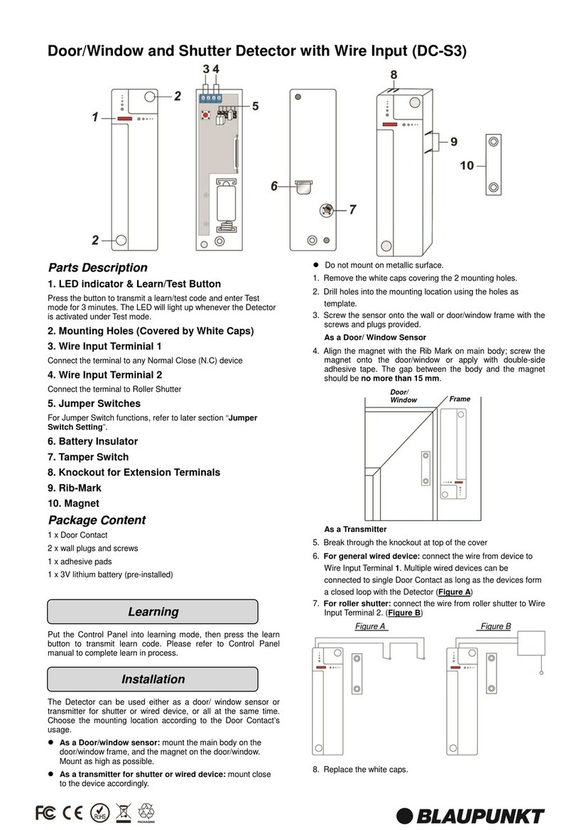
'RRU:LQGRZDQG6KXWWHU'HWHFWRUZLWK:LUH,QSXW'&6
Parts Description:
/('LQGLFDWRU/HDUQ7HVW%XWWRQ
3UHVVWKHEXWWRQWRWUDQVPLWDOHDUQWHVWFRGHDQGHQWHU7HVWPRGH
for 3 minutes. The LED will light up whenever the Detector is
activated under Test mode.
0RXQWLQJ+ROHV&RYHUHGE\:KLWH&DSV
:LUH,QSXW7HUPLQLDO
Connect the terminal to any Normal Close (N.C) device
:LUH,QSXW7HUPLQLDO
Connect the terminal to Roller Shutter
-XPSHU6ZLWFKHV
For Jumper Switch functions, refer to later section “Jumper Switch
Setting”.
%DWWHU\,QVXODWRU
7DPSHU6ZLWFK
.QRFNRXWIRU([WHQVLRQ7HUPLQDOV
5LE0DUN
10. Magnet
Package Content
1 x Door Contact
[:DOOSOXJVDQGVFUHZV
1 x Adhesive pads
[9OLWKLXPEDWWHU\SUHLQVWDOOHG
Put the Control Panel into learning mode, then press the learn
EXWWRQWRWUDQVPLWOHDUQFRGH3OHDVHUHIHUWR&RQWURO3DQHOPDQXDO
to complete learn in process.
7KH 'HWHFWRU FDQ EH XVHG HLWKHU DV D GRRUZLQGRZ VHQVRU RU
transmitter for shutter or wired device, or all at the same time.
Choose the mounting location according to the Door Contact’s
usage.
$V D 'RRUZLQGRZ VHQVRU PRXQW WKH PDLQ ERG\ RQ WKH
door/window frame, and the magnet on the door/window.
0RXQWDVKLJKDVSRVVLEOH
$VDWUDQVPLWWHUIRUVKXWWHURUZLUHGGHYLFH mount close
to the device accordingly.
'RQRWPRXQWRQPHWDOOLFVXUIDFH
1. Remove the white caps covering the 2 mounting holes.
2. Drill holes into the mounting location using the holes as
template.
3. Screw the sensor onto the wall or door/window frame with the
screws and plugs provided.
$VD'RRU:LQGRZ6HQVRU
$OLJQ WKH PDJQHW ZLWK WKH 5LE 0DUN RQ PDLQ ERG\ VFUHZ
WKHPDJQHWRQWRWKHGRRUZLQGRZRUDSSO\ZLWKGRXEOHVLGH
DGKHVLYHWDSH7KH JDSEHWZHHQ WKHERG\ DQGWKHPDJQHW
VKRXOGEHno more than 15 mm.
$VD7UDQVPLWWHU
5. Break through the knockout at top of the cover
)RU JHQHUDO ZLUHG GHYLFH connect the wire from device
WR :LUH ,QSXW 7HUPLQDO 0XOWLSOH ZLUHG GHYLFHV FDQ EH
connected to single Door Contact as long as the devices form
a closed loop with the Detector )LJXUH$
)RUUROOHUVKXWWHUFRQQHFWWKHZLUHIURPUROOHUVKXWWHUWR:LUH
Input Terminal 2. )LJXUH%
8. Replace the white caps.
Door/Window Frame
Figure A Figure B
Learning
Installation

ART. 35/09175-00 PAGINA 4 DI 4
Activation
$IWHULQVWDOODWLRQWKH'HWHFWRUZLOOEHDFWLYDWHGXQGHUWKH
following conditions:
1.:KHQWKHGRRULVRSHQHGDQGPDJQHWPRYHVDZD\IURPWKH
PDLQERG\WKH5HHG6ZLWFKZLWKLQWKH'HWHFWRUZLOOEHDFWLYDWHG
2.:KHQWKH1RUPDO&ORVH1&GHYLFHFRQQHFWHGWR:LUH,QSXW
Terminal 1 is activated (opened).
3.:KHQWKHSXOOFRUGRIWKHUROOHUVKXWWHUFRQQHFWHGWR:LUH,QSXW
Terminal 2 is pulled down or retracted for set distance.
Please refer to Jumper Switch Setting section below for
setting roller shutter cord activation distance.
Tamper Switch
7KH 7DPSHU 6ZLWFK ZLOO EH FRPSUHVVHG DJDLQVW WKH PRXQWLQJ
surface when the Detector is properly installed.
7KHWDPSHUVZLWFKZLOOEHDFWLYDWHGZKHQWKH'HWHFWRULVUHPRYHG
from the mounting location, or when its cover is removed.
:KHQ WKH WDPSHU VZLWFK LV WULJJHUHG WKH 'HWHFWRU ZLOO VHQG D
signal to the Control Panel to notify the situation.
Test Mode
Press the Test Button to enter Test mode for 3 minutes.
Under Test mode, the LED indicator will light up every time the
Detector is activated.
LED Indicator
Off Normal Operation
On (2 seconds)
:KHQ7DPSHU6ZLWFKLVWULJJHUHG
-The Detector is activated (door opened/wired
device triggered/roller shutter activated) under
ORZEDWWHU\WDPSHUWULJJHUHGRU7HVWPRGH
Battery
7KH 'HWHFWRU XVHV RQH 9 $$ OLWKLXP EDWWHU\ DV LWV SRZHU
VRXUFH,WDOVRIHDWXUHVORZEDWWHU\GHWHFWLRQIXQFWLRQWRQRWLI\WKH
&RQWURO3DQHOZKHQEDWWHU\YROWDJHLVORZ
:KHQWKH'HWHFWRULVRQORZEDWWHU\IROORZWKHSURFHGXUHEHORZ
WRFKDQJHWKHEDWWHULHV
1. Remove the Detector from mounting location, open the
cover.
2. 5HPRYHWKHROGEDWWHU\
3. 3UHVVWKHOHDUQEXWWRQVHYHUDOWLPHVWRIXOO\GLVFKDUJH
4. ,QVHUWWKHQHZEDWWHULHVREVHUYLQJFRUUHFWSRODULW\
5. Replace the cover and re-install the Detector at mounting
location.
The jumper switches provides setting option for Door Contact
functions. Each jumper switch has 2 pins; the jumper setting is
GHWHUPLQHGE\KRZWKHMXPSHULVLQVWDOOHGRQWKHSLQV
-XPSHU2Q
The jumper link is
inserted connecting
the two pins
-XPSHU2II
if the jumper link
is removed or
parked on one pin.
The Door Contact has 5 jumper switches, marked JP1, JP3, JP5,
-3-3RQWKH3&%ERDUGIURPOHIWWRULJKW
-3±7HVW0RGH
This jumper is used to put the Door Contact into
permanent Test Mode.
21 The Door Contact is set to Test Mode permanently.
<RXGRQRWQHHGWRSUHVVWKH/HDUQ7HVWEXWWRQWR
enter Test Mode
2)) The Door Contact is set to Normal Mode.
<RXFDQVWLOOSUHVVWKH/HDUQ7HVWEXWWRQWRHQWHU7HVW
Mode temporarily for 3 minutes. (Factory Default)
-3±5HHG6ZLWFK
7KLVMXPSHULVXVHGWRHQDEOHRUGLVDEOHGWKH'RRU
Contact’s Reed Switch.
21 The Reed Switch is 'LVDEOHG. The Door Contact can
RQO\EHDFWLYDWHGE\WKH:LUH,QSXW7HUPLQDOV
2)) The Reed Switch is (QDEOHG. The Door Contact can
EHDFWLYDWHGE\ERWK5HHG6ZLWFKDQG:LUH,QSXW
Terminals. )DFWRU\'HIDXOW
-3-3-3±5ROOHU6KXWWHU3XOO&RUG
$FWLYDWLRQ'LVWDQFH
This jumper is used to set the distance the pull cord on the roller
VKXWWHUQHHGVWRWUDYHOEHIRUHWKH'RRU&RQWDFWLVDFWLYDWHG
7KHGLVWDQFHLVPHDVXUHGE\WKHQXPEHURISXOVHVLJQDOVHQWWR
:LUH,QSXW7HUPLQDOZKHQWKHSXOOFRUGLVSXOOHGRUUHWUDFWHG
2QO\RQHRIWKHMXPSHUVFDQEHWXUQHGRQDWDWLPH
-3 21 7KH 'RRU &RQWDFW ZLOO EH DFWLYDWHG DIWHU GHWHFWLQJ
pulses from roller shutter within 10 seconds.
-3 21 7KH 'RRU &RQWDFW ZLOO EH DFWLYDWHG DIWHU GHWHFWLQJ
pulses from roller shutter within 10 seconds.
)DFWRU\'HIDXOW
-3 21 7KH 'RRU &RQWDFW ZLOO EH DFWLYDWHG DIWHU GHWHFWLQJ
pulses from roller shutter within 10 seconds.
Environmental Condition
-10°C to 40°C, relative humidity 85% non-condensing.
Radio
0+])0
User information ex art. 26 D. 49/2014
The symbol labelled on the appliance (Annex IX D. 49/2014) indicates that
WKHUXEELVKLVVXEMHFWWR´VHSDUDWHFROOHFWLRQµDQGLWKDVEHHQSODFHGRQWKH
Italian market after the December 31, 2010.
7KH XVHU PXVW WKHUHIRUH DVVLJQ RU KDYH FROOHFWHG WKH UXEELVK WR D
treatment facility according to indications by the local administration, or
KDQGLWRYHUWRWKHUHVHOOHULQH[FKDQJHIRUDQHTXLYDOHQWQHZSURGXFW7KH
separate collection of the rubbish and the subsequent treatment, recycling
and disposal operations encourage the production of appliances made
ZLWK UHF\FOHG PDWHULDOV DQG UHGXFH QHJDWLYH HͿHFWV RQ KHDOWK DQG WKH
HQYLURQPHQWFDXVHGE\LPSURSHUWUHDWPHQWRIUXEELVK
,QWKHFDVHRIYHU\VPDOO:(((QRH[WHUQDOGLPHQVLRQPRUHWKDQFP
the user is eligible to get free of charge assignation to retail shops with
sales areas relating to EEE of at least 400 m².
',675,%87('%<
ELCART DISTRIBUTION SPA
Via Michelangelo Buonarroti, 46
20093 COLOGNO MONZESE (MI)
ITALY
Operation
Jumper Switch Setting
6SHFL¿FDWLRQ
Table of contents
Languages:
Other Blaupunkt Security Sensor manuals

Blaupunkt
Blaupunkt HD-S1 User manual

Blaupunkt
Blaupunkt IR-S1L User manual

Blaupunkt
Blaupunkt CO-S1 User manual

Blaupunkt
Blaupunkt IR-S4 User manual

Blaupunkt
Blaupunkt IR-S1 User manual

Blaupunkt
Blaupunkt DC-S4 User manual

Blaupunkt
Blaupunkt DC-S2 User manual

Blaupunkt
Blaupunkt ISD-WD1 User manual

Blaupunkt
Blaupunkt SD-S1 User manual

Blaupunkt
Blaupunkt HD-S1 User manual
Popular Security Sensor manuals by other brands

Veeder-Root
Veeder-Root TLS-3 Series installation guide

LST
LST B524IEFT-1 Specification sheet

Dors
Dors 1250 user manual

elobau
elobau 1655 V Series Translation of the original operating instructions

Magnum Energy
Magnum Energy M9-ML2 Product installation guide

Hytronik
Hytronik HIR28 Installation and instruction manual