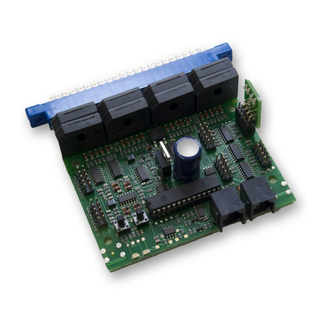
Digitrax BXP88 User manual

© 2017 Digitrax, Inc. www.digitrax.com— 1 —
Features:
▪DCC Occupancy Detection supports up to 8 Detection Sections letting you
know when equipped rolling stock is in a detection section on your layout.
▪One Transponding Zone per Detection Section lets you know the location of
transponder-equipped locos or rolling stock.
▪Intelligent Automatic short-circuit and over-current power management
for each Detection Section, improves reliability by avoiding most booster
shutdowns.
▪Connects to LocoNet to transmit Detection Section occupancy, Transponding
and track power information.
▪Detects any powered locomotives in a Detection Section.
▪Detects rolling stock equipped with resistor wheel sets.
▪Identify where specic rolling stock is on your layout with Digitrax transpon-
der-equipped locos and rolling stock.
▪Plug and Play with Digitrax DCC systems with automatic Railsync polarity
detection.
▪LED output headers for front panel indication of Detection Section occupancy,
Transponding, and power status.
▪Easy-connect pluggable track wire terminal blocks can plug-in straight or at
right angles.
▪3 Amp capacity per Detection Section , 8 Amp total unit capacity.
▪Automatically updates status at track power on.
▪Operations Mode Read Back allows you to read CV values of decoders
equipped with transponders when on track.
▪Firmware update capability via IPL over LocoNet.
Parts List
1 BXP88 1 LT5 Tester
1 Instruction Manual
Digitrax Manuals and Instructions are updated periodically.
Please visit www.digitrax.com for the latest version of all manuals.
Complete Train Control
Run Your Trains, Not Your Track!
All Scales
LocoNet DCC Occupancy Detector with Transponding
and Power Management for 8 Detection Sections,
Transponding Zones, and Power Sub-Districts
BXP88

© 2017 Digitrax, Inc. www.digitrax.com— 2 —
1.0 Introduction
The BXP88 is a combination DCC occupancy detector, Transponding detector,
and intelligent power manager. It is designed to make transponding implemen-
tation easy and provide advanced DCC track management by communicating all
state information to LocoNet.
The BXP88 provides DCC occupancy detection that lets you know when any of
its 8 connected Detection Sections are occupied by rolling stock that is equipped
for detection. Any rolling stock equipped with a decoder or other load that
draws current can be detected. This occupancy detection capability is the rst
step toward prototypical control of your rolling stock, layout signaling, realistic
surround sound eects and more realistic modeling on your layout. In addition
to detection the BXP88 also enables transponding on your layout. Transponding
allows you to track and inform LocoNet of the layout location and identication
of rolling stock equipped with transponders. Finally, the BXP88 provides auto-
matic power management for each Detection section. Each Detection section acts
as an independent power sub-district with short circuit and over-current power
management. This allows for more reliable layout operations by preempting
most booster shutdowns.
On your Digitrax system, the BXP88 reports detection section occupancy,
transponding and track power status to the system via its LocoNet connection.
This makes occupancy and transponding information available for use by any
LocoNet device hooked up to LocoNet. For instance, the information can be used
by a computer and the SE8c to set signals or by a computer program for dispatch
control. Occupancy and transponding information can also be reported via a user
installed LED display panel.
The number of BXP88s you use on your layout is determined by how many areas
of track you want to monitor and how automated you want your layout to be,
more Detection Sections require more BXP88s. Installing the BXP88 on your
layout is easy and will make more prototypical and reliable operations possible.
2.0 Terminology
Understanding this terminology will help you best apply the BXP88 to your
layout.
Direct home wiring is a DCC layout wiring method where each power dis-
trict and its booster tracks are electrically isolated. The track within each power
district uses a “common return” wiring method for occupancy detection and/or
power management. Direct home wiring is the wiring method recommended by
Digitrax and required for proper operation of the BXP88

© 2017 Digitrax, Inc. www.digitrax.com— 3 —
Power district is the power wiring, track, components and equipment attached
to that wiring, driven by a single properly isolated booster. The track for a power
district is double gapped on both ends of the district. The BXP88 is used to set up
detection/transponding sections within one power district.
Power sub-district is the wiring, components and equipment that are con-
trolled from both power bus wires by their own power management device. Each
of the 8 Detection/Transponding sections on the BXP88 acts as its own sub-dis-
trict implementing short circuit and over current protection.
Detection/Transponding Common is the common return used within a
properly electrically isolated power district for implementing occupancy detec-
tion.
Security element is the plant, including track, associated with any reporting,
interlocking and/or signaling for that track section.
Whole layout common rail is a method of wiring layouts where power districts
and their boosters are connected electrically by a common rail or common power
bus return wire. This method is traditionally used for conventionally controlled
layouts. Whole layout common is not compatible with the BXP88.
Detection/Transponding Section is a section of track gapped on one or both
rails and connected to an occupancy/transponding detector so that the detector
can sense the presence of a loco (or other specially equipped cars) in that section
of track and identify transponding equipped locos and rolling stock. Traditionally
with BDL168/RX4 combinations Detection sections could be combined inside
Transponding Zones. With the BXP88 each of its 8 Detection Sections act as
both an occupancy and transponding detector. For simplicity, these sections will
be referred to as Detection Sections in this document. Note the BXP88 does not
support detection/transponding within an automatic reversing section.
Occupancy detector is a device that senses the presence of a locomotive (or
specially equipped cars) in a section of track that is set up for occupancy detec-
tion. Occupancy detectors also provide feedback to indicate occupancy. This
feedback may be in the form of a lamp on a control panel or it may be a feedback
message sent to the system that can be used by other layout devices. Also called a
block occupancy detector on conventional layouts. Detectors are not covered by
the DCC Standards or Recommended Practices.
Transponder is an electronic device that is installed in rolling stock and can be
assigned a unique address. Transponders in rolling stock provide information to
transponder detectors installed on the layout tracks. This lets the system deter-
mine in which Detections Section or track the transponder is currently located.
Transponders are included in all current production Digitrax decoders and many
older models as well. TL1 & TF4 function-only decoders with Transponding are
available as separate units that can be added to locos with existing decoders or

© 2017 Digitrax, Inc. www.digitrax.com— 4 —
to other rolling stock without decoders if you want to use them for transponding
only and don’t need motor control.
Transponder detector is an electronic device as part of a detection section on
the layout that receives the information broadcast from a transponder. The tran-
sponder detector sends feedback to the system to let it determine the detection
section location of any given transponder at any time. The BXP88 incorporates
transponding and occupancy detectors in each of its 8 detection sections.
Transponder zone is an area of track that may be single gapped on one rail or
double gapped on both ends and equipped with a transponder detector. Tradi-
tionally with BDL168/RX4 combinations Detection sections could be combined
inside Transponding Zones. With the BXP88 each of its 8 detection sections
act as both an occupancy and transponding detector, so transponding zones are
incorporated into each detection section.
3.0 Plan Your Feedback System
Before you begin installing BXP88s you should carefully analyze your layout and
what you want to achieve with your feedback system. The key to proper wiring for
occupancy detection/transponding is planning. Your layout will be divided into
Detections sections that can range anywhere from several inches to many feet in
length. This process is custom to each unique layout, with the number and length
of a detection sections varying depending on your layout, train length and the
purpose of the detection/transponding. The BXP88 provides Detection, Tran-
sponding, and Power Management in each of its 8 detection sections, you should
consider if every section on your layout needs these features. Transponding is
often not needed in all detection sections of your layout and other occupancy
only detectors could be used. By using transponding and other types of detection
technologies in tandem, you will be able to get excellent performance and results
at the lowest possible cost.
It is best to plan your detection sections based upon the operations you want to
accomplish on your layout before cutting track gaps and installing a BXP88 or
other detection devices. For instance, a grade level signal crossing may require
from two to four dierent detection sections with occupancy detection in order
to control the lights and gates operating, for trains traveling in either direction.
Signal lights will require information from one or more detection sections in front
and behind of the signal mast to function like the prototype.
Occupancy detection is not only useful, but critical, if operating a hidden staging
area and will let you know which tracks are occupied. In your initial wiring instal-
lation, not all sections have to be connected to BXP88s; they can be connected to
a terminal strip and then to boosters or power management devices. Additional
BXP88s can then be inserted later as needed to further develop your layout.

© 2017 Digitrax, Inc. www.digitrax.com— 5 —
4.0 BXP88 Installation Notes
The BXP88 is only compatible for use with Direct Home Layout wiring and re-
quires a LocoNet compatible system for Detection/Transponding Reporting. The
BXP88 is also not designed for use with Auto Reversing sections.
The BXP88 can be located for convenience and ease of installation. Consider
placing these units on swing-down panel(s) at the layout fascia to support a sec-
tion of close by tracks. This allows easy front access during construction, debug
and maintenance, without having to work upside down under the layout.
Ensure that booster and track feeds are sucient to carry currents and detect
short circuits. We recommend at minimum 14AWG bus lines and 22AWG feeder
connections up to the rails.
When installing multiple BXP88s or BXP88s in conjunction with other devices
ensure that Rail A and Rail B are consistent between all Power Districts so rolling
stock can cross the double gaps without short circuits. Rail A and B inputs to the
BXP88 can be switched as needed to match existing wiring, the BXP88 automati-
cally sets railsync.
An LT5 tester is included with the BXP88, and optional fascia LED panels can be
constructed following the instructions in section 10.3 .
The BXP88 does not need to be externally powered. An optional auxiliary 9V
150ma DC power supply may be used to allow the BXP88 to remain on when
track power is lost. Multiple BXP88s can be powered from the same supply as
long as 150ma is available for each unit. The optional 9V DC supply should not
be shared with any other non-BXP88 devices.
The primary advantage to additional auxiliary powering of the BXP88 is the
BXP88 can default to report Detection Sections as occupied when track power
is lost. This allows for signal or computer logic to respond appropriately. Addi-
tionally, if the BXP88 is auxiliary powered it can report other track and LocoNet
faults via its LED indicator connectors.
When a BXP88 is powered up on a Digitrax Layout it will automat-
ically disable analog stretching, by setting OPSW 20= Closed in the
Command Station. The BXP88 is not compatible with analog mode
stretching, and you will not be able to run conventional DC loco-
motives at address 00. All locomotives will need a DCC decoder to
operate.

© 2017 Digitrax, Inc. www.digitrax.com— 6 —
5.0 BXP88 Installation
1. Power down your Digitrax LocoNet System.
2. Determine an appropriate mounting location for your BXP88.
3. Mount the BXP88 in the appropriate location. The BXP88 is equipped with
removable screw terminals for easy wiring once the unit is mounted.
4. Connect the “BGND” terminal to the General Return bus that connects all
your boosters. This should be a heavy gauge wire.
5. Connect “RA” to the Rail A terminal on the booster that will be powering the
8 sections.
6. Connect “RB” to the Rail B terminal on the booster that will be powering the
8 Sections.
Note: Rail A and Rail B should consistent between all Power Districts, you may
need to switch the Rail A and Rail B connections in the above steps.
7. Connect “RAX” to the common Rail A for all 8 detection sections.
8. Connect “DS1”-“DS8” to each isolated Rail B detection sections.
9. Connect to LocoNet via the LocoNet port using a known good LocoNet Cable.
10. Connect optional auxiliary 9V 150ma DC power supply using the power
barrel plug connector.
See Figure 1: BXP88 Installation Example for a typical installation.
6.0 Turning on your system and conguring the
BXP88
Once you have installed your BXP88, you may turn on your system. There are
several tests you can perform to ensure that the BXP88 is properly functioning.
1. Power on your Digitrax System and the sections of your layout where the
BXP88 is connected.
2. Using a small piece of wire or some other conductor short the “RA” and “RB”
terminals together the booster connected to the BXP88 should reliably shut
down.
3. Test each detection sections 1-8 by shorting across the tracks they are con-
nected too. Using the LT5 tester included plugged into the “DS1-4 LEDS”
and “DS5-8 LEDS” header you should see each corresponding Detection
section LED blink fast when the short is present.
4. If the Booster powering the BXP88 shuts down during these tests you will
need to lower the resistance of your wiring.
5. For additional Detection and Transponding Testing please refer to sections
12 and 13.

© 2017 Digitrax, Inc. www.digitrax.com— 7 —
BXP88
ZONE OPS ID
DS1 DS2 DS3 DS4 DS1-4 LEDS BGND RA RB RAX DS5 DS6 DS7 DS8 DS5-8 LEDS
EZ
RTS
DCS 240
R
LOCONET
A B
R
C
USB
PWR PROG NET
TRACK
STATUS
MODE
RUN
OP
SLEEP
SCALE
O/G
N
HO
+
P
A
G
R
P
B
R
B
R
A
5A LOCO
RESET
-
8A
Detection
Section 1
Detection
Section 2
Detection
Section 3
Detection
Section 4
Detection
Section 5
Detection
Section 6
Detection
Section 7
Detection
Section 8
Figure 1: BXP88 Installation Example
General Return
LocoNet: to
other devices
LT5 LED connectors
DS5-DS8
LT5 LED
connectors
DS1-DS4
Common Rail A
Isolated Rail B detection
sections

© 2017 Digitrax, Inc. www.digitrax.com— 8 —
7.0 Setting BXP88 Board ID and corresponding
Transponding Zone IDs
Setting up your Board ID for your BXP88s should be carefully considered. Each
BXP88 automatically assigns Detection Sections and Transponding Zones based
o the BXP88’s Board ID. For example, a BXP88 with a board ID of 001 (factory
default) will report for detection sections 01-08 and transponding zones 00-07.
A BXP88 with a board ID of 002 will report for detection sections 09-16 and
transponding zones 08-17. Each subsequent ID will generate corresponding IDs.
The BXP88 supports board addresses 001-256. When planning your layout it is
important that these section and zone IDs do not overlap. Additional consider-
ations should be taken with incorporating the BXP88s into systems using other
detection or transponding products such as the BDL168 and RX4. Please see the
Digitrax Tech Support Depot for additional information on conguring device
Board IDs.
To set your BXP88 Board ID:
1. Ensure that your BXP88 is properly connected and powered on.
2. Press and hold the ID button for approximately 4 seconds until the ID LED
ashes red, then release it. The ID LED will ash alternating red and green.
This let’s you know that you are in board address set up mode.
3. Connect a Digitrax throttle to the BXP88s LocoNet port. (This can only be
done with a Digitrax LocoNet throttle or equivalent software).
4. Go into SWITCH mode on the throttle. Select the switch number that corre-
sponds to the board address you want to set and issue a closed “c” command
to set the board address. The board address is changed as soon as you issue
the SWITCH command.
5. Once the Board ID is set the ID LED will go back to solid green.
Please see your specic throttle manual for details on how to issue SWITCH
commands.
8.0 Customizing Your BXP88 – Setting up Option
Switches
A BXP88 with Factory-default settings will generally work on Digitrax DCC
layouts with no modications, and only the Board ID needs to be set uniquely for
each BXP88 to report allocated Detection section and Transponding Zone num-
bers correctly onto LocoNet.
The implemented option switches and settings you can use to customize your
BXP88 are indicated in Table 1: BXP88 Option Switches. These option switch-
es on your BXP88 are set up using a Digitrax throttle’s SWITCH commands.

© 2017 Digitrax, Inc. www.digitrax.com— 9 —
SWITCH mode is normally used for operating turnouts by issuing closed (“c”)
or thrown (“t”) commands. In the case of your BXP88, each switch address is a
BXP88 option switch when it is in OPSW setup mode.
How to read back and change BXP88 Option Switches (OpSw):
1. Power up your BXP88 and connect it to LocoNet.
2. Connect a Digitrax throttle to one of the BXP88’s LocoNet connectors.
3. Press the OPS button for about 2 seconds, then release it. The red OPS and
green ID LEDs will ash alternately to let you know that you are in option
switch setup mode.
4. Go into SWITCH mode on your throttle. Dial up the switch number that cor-
responds to the OpSw you want to change and issue a closed “c” or thrown
“t” command to set the OpSw to the desired setting. The OpSw is changed as
soon as you issue the SWITCH command.
5. When BXP88 OpSws are set up as desired, press the OPS button for about 2
seconds and release it, the BXP88 will exit option switch set up mode.
Option
Switch # Function Default
OpSw 04 c=slower short circuit detection
t=normal short circuit detection t
Opsw 05 c=transponding enabled
t=transponding disabled c
OpSw 07 c=disable fast nd
t=enable fast nd t
OpSw 10 c=enable power manager
t=disable power manager c
Opsw 11 c=enable power manager reporting to LocoNet
t=disable power manager reporting to LocoNet c
Opsw 14 c= high detection sensitivity
t= regular detection sensitivity t
Opsw 15 c=do not send occupied message on LocoNet when faulted
t=send occupied message on LocoNet when faulted t
Opsw 33 c= Disable Operations Mode Readback
t=enable Operations Mode Readback t
Opsw 40 c=set factory default t
Opsw 41 c=disable occupancy reporting for Detection Section 1
t=enable occupancy reporting for Detections Section 1 t
Opsw 42 c=disable occupancy reporting for Detection Section 2
t=enable occupancy reporting for Detections Section 2 t
Table 1: BXP88 Option Switches

© 2017 Digitrax, Inc. www.digitrax.com— 10 —
Option
Switch # Function Default
Opsw 43 c=disable occupancy reporting for Detection Section 3
t=enable occupancy reporting for Detections Section 3 t
Opsw 44 c=disable occupancy reporting for Detection Section 4
t=enable occupancy reporting for Detections Section 4 t
Opsw 45 c=disable occupancy reporting for Detection Section 5
t=enable occupancy reporting for Detections Section 5 t
Opsw 46 c=disable occupancy reporting for Detection Section 6
t=enable occupancy reporting for Detections Section 6 t
Opsw 47 c=disable occupancy reporting for Detection Section 7
t=enable occupancy reporting for Detections Section 7 t
Opsw 48 c=disable occupancy reporting for Detection Section 8
t=enable occupancy reporting for Detections Section 8 t
Opsw 50 c=do not allow selective transponding disabling by Opsw 51-58
t=allow selective transponding disabling by Opsw 51-58 t
Opsw 51 c=disable transponding reporting for Detection Section 1
t=enable transponding reporting for Detections Section 1 t
Opsw 52 c=disable transponding reporting for Detection Section 2
t=enable transponding reporting for Detections Section 2 t
Opsw 53 c=disable transponding reporting for Detection Section 3
t=enable transponding reporting for Detections Section 3 t
Opsw 54 c=disable transponding reporting for Detection Section 4
t=enable transponding reporting for Detections Section 4 t
Opsw 55 c=disable transponding reporting for Detection Section 5
t=enable transponding reporting for Detections Section 5 t
Opsw 56 c=disable transponding reporting for Detection Section 6
t=enable transponding reporting for Detections Section 6 t
Opsw 57 c=disable transponding reporting for Detection Section 7
t=enable transponding reporting for Detections Section 7 t
Opsw 58 c=disable transponding reporting for Detection Section 8
t=enable transponding reporting for Detections Section 8 t
Table 1: BXP88 Option Switches
9.0 Auto-Reversing
The power management timing used by the BXP88 may not be compatible with
some auto-reverser control items connected upstream on the RA and RB input
connections. A downstream auto-reverser on a DS will show that Detection Sec-
tion as occupied at all times, but Transponding will work. An upstream auto-re-
verser will reverse all of a BXP88’s detection sections tracks, so these 8 detection
sections can only be used within the same single reverse area or power district.

© 2017 Digitrax, Inc. www.digitrax.com— 11 —
10.0 Occupancy/Transponding Indication
The BXP88 can report occupancy and Transponding information via the LocoNet
connection or via direct output to a user created LED panel.
10.1 LocoNet Devices
The BXP88 provides occupancy and transponding messages to LocoNet that can
be used by computer software for a visual display of occupancy and transponding
status on the layout or to other devices on the layout. For instance layout control
software can use these messages to control signals on the layout via a Digitrax
SE8c. See the operating manual of your computer software or the SE8C for de-
tails on installation and operation.
10.2 LT5 Tester
The BXP88 provides two LT5 LED compatible outputs labeled “DS1-4 LEDS”
and “DS5-8 LEDS” and the supplied LT5 tester can be plugged in here to provide
visible detection section, power state and fault information for setup, debug and
running. This will help you with layout wiring and troubleshooting for transpon-
ding & detection.
LT5 Indications Meaning
Detection Section LED on Solid Detection Section is Occupied
Detection Section LED is Blinking Slow Detection Section is Occupied and Tran-
sponding
Detection Section LED is Blinking Fast Detection Section is in Short Circuit
Zone LED is on Solid Normal Operation, no faults
Zone LED o blinking on once repeating
every 2 seconds Track Power is o, RailSync not detected
Zone LED o blinking on twice repeating
every 2 seconds Rail A or Rail B unpowered
Zone LED o blinking on 3 times repeating
every 2 seconds Internal Voltage Problem
Zone LED o blinking on 4 times repeating
every 2 seconds LocoNet Error or Disconnected
Note: When a fault is detected a detection sections will show and report as Oc-
cupied and detection section LEDS will be lit. This is the default fail-safe logic,
reporting can be changed with OpSw 15.
Table 2: LT5 LED Indications

© 2017 Digitrax, Inc. www.digitrax.com— 12 —
10.3 Panel Indicator Wiring
You can build a display panel with a track schematic and LEDs to indicate track
occupancy by connecting LEDs to the LT5 compatible output connectors on the
BXP88. For a panel display of occupancy status made up with user supplied
LEDs, connect to the four 0.1” 2x5 headers, and wire up high brightness LEDs
as shown in Figure 3: LED Panel Indicators Wiring. The plugs and ribbon cable
included in the Digitrax SDCK Signal Driver Cable Kit can be used.
The BXP88 incorporates current setting resistors to set the LT5 LED current typi-
cally to about 1~3mA. If you need higher LED drive currents you can use external
transistors etc. to amplify the LED current.
The LT5 header drive from the BXP88 is active high at about +3.5 volts, via a
1 Kohm resistor. Note that the ribbon cable includes separate ground return
conductors for each LED that allow a 10 conductor ribbon cable to be split into 5
pairs to conveniently routed to individual LEDS. Be sure to connect the +ve active
detection section output wires to the LED anodes. Do not connect any LT5 wiring
to other voltages as this may cause damage and void the warranty.
Figure 2: LT5 Tester
LED for DS1 or DS5
LED for DS3 or DS7
Zone Power LED
LED for DS2 or DS6
LED for DS4 or DS8
Ribbon Cable and Plug
DS1 or DS5
DS4or DS8
DS2 or DS6
DS3 or DS7
Zone Power
Figure 3: LED Panel Indicators Wiring

© 2017 Digitrax, Inc. www.digitrax.com— 13 —
11.0 Setting Up Locos & Other Rolling Stock for
Transponding
1. Your locomotives or other rolling stock that you want to use for transponding
must be equipped with either a transponder device or a decoder with Digi-
trax transponder capability included. Transponder devices such as the TD1
& TL1 can be added to non-transponding decoder installations. These de-
vices are very small and easy to install. If you have not put decoders in your
locos, it is easy to use a transponder equipped decoder and then you won’t
have to add a second board inside the loco. All Digitrax current production
decoders support Digitrax Transponding.
2. When you install a wired transponder equipped decoder, you should also
install a load resistor of between 270 ohms & 470 ohms between the blue and
white decoder leads. If you are using a board replacement, and some other
decoders the resistor may already be installed on the decoder. Digitrax com-
patible transponder current pulse generation uses the F0F decoder function
or white lead that is also used for the forward light function. Transponding
will not aect the operation of the forward light but you may see a slight glow
when the light is turned o because of the way transponding works.
Notes: If the resistor is not connected between the blue & white/F0F leads,
then the locomotive will transpond in only one orientation on the track. If
you are using a DH126D, DH166D, TD-1 or TL-1 to equip your loco or rolling
stock for transponding, you won’t need to install the resistor because it is
already included in the decoder.
3. Enable transponding in the transponder equipped decoder by programming
CV61 to a value of 02.
4. Place the loco on the track, select it and run it back & forth. Verify that
transponding is working in that orientation. If transponding is not working,
be certain if required that the resistor described in step 2 above is installed
properly between the white and blue leads of the decoder.
5. Pick up the loco and turn it around on the track, select it and run it back
and forth again. Verify that transponding is working in that orientation. If
transponding is not working, be certain that the resistor described in step 2
above is installed properly between the white and blue leads of the decoder.
NOTE: Locos must be selected in the system for transponding to work.
12.0 Occupancy Debug
Use the LT5 provided or attached LED indicator panel with your BXP88 as
described in Sections 10.2 & 10.3. The LT5 tester or and attached LED indicator
panel allows you to easily check the zone sensitivity (typically 22 Kohms to give
detection). This also aids in the determination of detection number and activi-

© 2017 Digitrax, Inc. www.digitrax.com— 14 —
ty for a track detection section. Many detection problems are related to wiring
problems or poor connections to the detection section rather than to the actual
BXP88. By using the display array, you can eliminate the wiring issues from the
equation and be sure that the BXP88 is set up correctly.
Remember, if the zone power is OFF, the occupancy LEDs should be set up so
that they will be on to be sure that signaling systems or a CTC/dispatcher will see
the detection section in its most restricted aspect.
12.1 LocoNet Debug
The BXP88 reports information to LocoNet, so be sure that the connection is
working. In normal operations the red “OPS” LED will blink ON briey when
valid incoming LocoNet messages are seen, conrming a good LocoNet network
connection. The BXP88 will blink the ZONE led green when a state message is
sent by the BXP88 to LocoNet.
12.2 Analog Locomotives
Analog Locomotive are not compatible with the BXP88, all locomotives must be
equipped with a DCC decoder.
13.0 Using a Test Transponder for debugging
You can use a Test Transponder as follows:
1. Use transponder capable decoder set up with a 470 ohm resistor between the
blue and white leads. This removes any lamp issues from initial transpon-
ding tests. The motor leads can be left unconnected/insulated and all other
leads except the red/black track connections should be insulated. Set CV61
to a value of 02 to enable transponding.
2. Ensure the BXP88 is properly connected to your Command Station/Booster
via Rail A and Rail B connections. Connect the BXP88 to your Command
Station/Booster using a Known good LocoNet cable. Connect an LT5 to the
“DS1-4 LED” header.
3. Use the rst Detection Section (DS1), hook RAX to the decoder RED lead and
DS1 to the decoder BLACK lead.
4. Power up the System and the BXP88 connected to the test decoder. Turn on
Track Power and select the decoder’s address in a throttle. (Decoder factory
defaults are Address 03).
5. DS 1 LED will blink steadily indicating that a valid transponder with that
address is being detected in that transponding zone.
14.0 FCC Information
Radio or TV Interference: (this information is MANDATED by the FCC) This
equipment has been tested and found to comply with the limits for a Class B
digital device, pursuant to part 15 of the FCC rules. These limits are designed to
provide reasonable protection against harmful interference when the equipment

© 2017 Digitrax, Inc. www.digitrax.com— 15 —
is operated in a residential environment. This equipment generates, uses and
can radiate radio frequency energy and, if not installed and used in accordance
with the instruction manual, may cause harmful interference to radio commu-
nications. However, there is no guarantee that interference will not occur in a
particular installation. If this equipment does cause harmful interference to radio
or television reception, which can be determined by turning the equipment o
and on, the user is encouraged to try to correct the interference by one or more of
the following measures:
• Reorient or relocate the receiving antenna.
• Increase the separation between the equipment and the receiver.
• Connect the equipment into an outlet on a circuit dierent from that to
which the receiver is connected.
• Consult the dealer or an experienced radio/TV technician for help.
Note: Any modications to the equipment not expressly approved by Digitrax
voids the user’s warranty and compliance with CFR 47 rules, as administered by
the Federal Communication Commission. Digitrax believes any properly installed
equipment following guidelines in this manual is unlikely to experience RFI
problems.
15.0 Warranty & Repair
Digitrax gives a one year “No Worries” Warranty against manufacturing defects
and accidental customer damage on all Digitrax command stations, boosters,
throttles, decoders, power supplies and layout control devices.
That’s it! A simple, straightforward warranty with no tricky language!
Visit www.digitrax.com for complete warranty details and instructions for
returning items for repair.
Please return warranty items directly to Digitrax - DO NOT return items
to place of purchase.

2443 Transmitter Road
Panama City, FL 32404
www.digitrax.com
Need Support?
helpdesk.digitrax.com
BXP88
LocoNet DCC Occupancy Detector with Transponding and
Power Management
Made in the USA
TM
Part 15, Class B
RFI Compliant
307-7008-000/
Table of contents
Other Digitrax Security Sensor manuals
Popular Security Sensor manuals by other brands
B.E.G.
B.E.G. LUXOMAT PD4-M-1C-C-SM Installation and operating instruction
Teleco
Teleco RAIN102H quick start guide
LI-COR
LI-COR LI-210R instruction manual
Gas Clip Technologies
Gas Clip Technologies Multi Gas Clip Operator's manual
YATO
YATO YT-73138 Original instruction
Honeywell
Honeywell C7076A operating instructions
