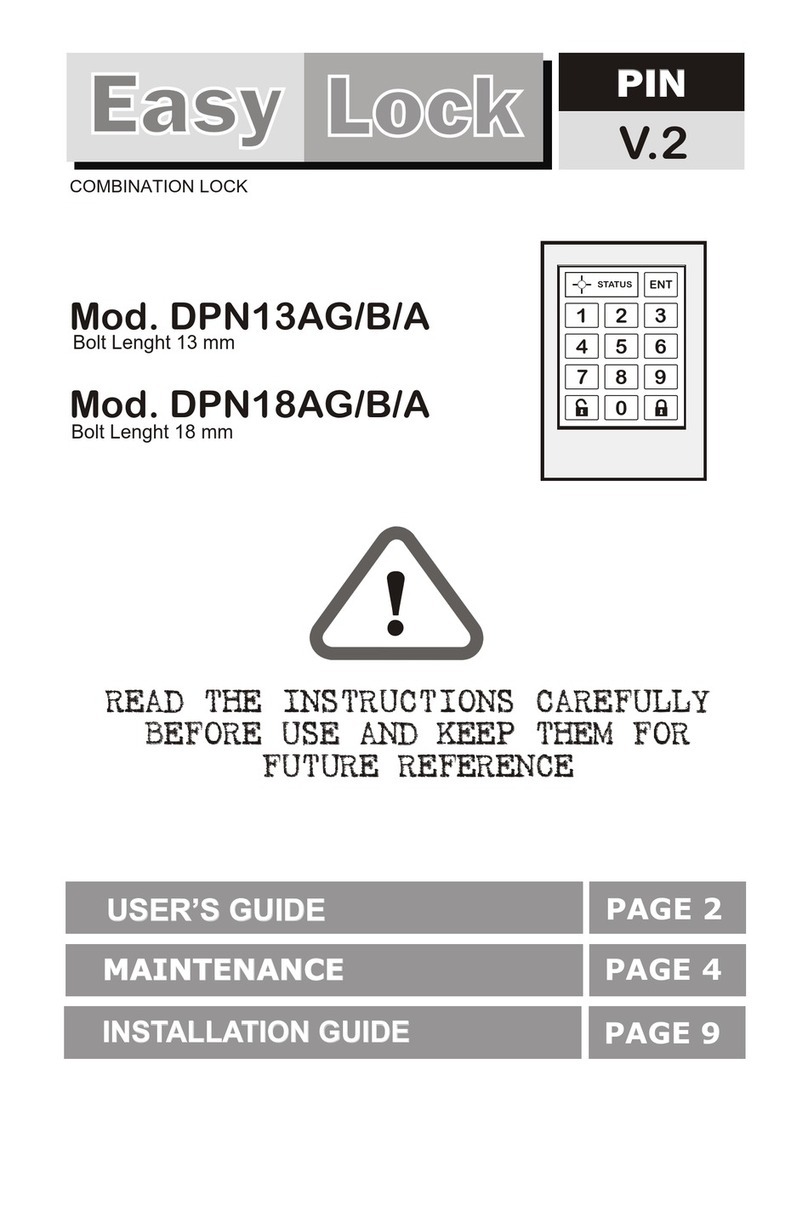
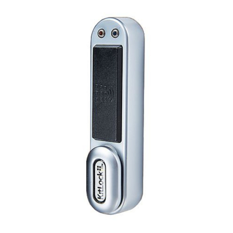
Digitron DRF13PG/B/A User manual

READ THE INSTRUCTIONS CAREFULLY
BEFORE USE AND KEEP THEM FOR
FUTURE REFERENCE
READ THE INSTRUCTIONS CAREFULLY
BEFORE USE AND KEEP THEM FOR
FUTURE REFERENCE
!
PAGE 8
PAGE 4
PAGE 2
MAINTENANCEMAINTENANCE
USER’S GUIDEUSER’S GUIDE
INSTALLATION GUIDEINSTALLATION GUIDE
Easy Lock
EasyEasy LockLock
RFIDRFID
125 Khz
2
5
8
0
1
4
7
3
ENT
STATUS
6
9
2
5
8
0
1
4
7
3
ENT
STATUS
6
9
FORMAT : UNIQUE - SOKIMAT Q5 - ATMEL T5557
Mod. DRF13PG/B/A
Mod. DRF18PG/B/A
PROXIMITY LOCK RFID 125 KHZ
Bolt Lenght - 13 mm
Bolt Lenght - 18 mm

Lean the TAG ( Card or Wristband ) to the centre of the sensor.
The LED will shortly flash 1 time every 2 seconds to indicate that the lock is
closed
Lean the PASSEPARTOUT Card to the centre of the sensor
Lean the TAG ( Card or Wristband ) used to close to the centre of the sensor.
When the lock is open the LED stays OFF.
CLOSING
SHARED USE :
The lock closes with any compatible TAG ( Card or Wristband ) and it will open
only with the same TAG used to close
OPENING
OPENING WITH PASSEPARTOUT CARD
PAG. 2
Led
Sensore
2
5
8
0
1
4
7
3
ENT
STATUS
6
9
USER’S GUIDEUSER’S GUIDE
NO
OKOK

By inserting the timer, the lock will open after an established time everytime it is closed.
To set the timer please follow the instruction below :
TIMER SETTING
For disconnecting the Timer proceed as above and use the TIMER card with value “0”.
With the lock “open” lean the special TIMER with the value of the hours that you wish
to program to the center of the sensor and remove the card when the LED turns “ON”.
When the lock is closed the LED will shortly flash 2 time every 2 seconds to indicate that
the lock is closed with the Timer “ON”.
PERSONAL USE
It is possible program the lock so that it works with a specific personal TAG
( Card or Wristband ).
With the lock “open” lean the special READ FIXED card to the center of the sensor and
remove the card only when the the LED turns “ON”.
Within 5 seconds ( before the LED turns “OFF” ) lean the personal compatible TAG
( Card or Wristband ) and remove the card only when the LED stays “ON” after has issued
short flashes.
After this procedure the lock will work only with the personal TAG ( Card or Bracelet )
programmed.
Note : with the personal use mode when the lock is closed the led does not flashes
To return in the mode Shared Use :
With the lock “open” lean the special FIXED ERASED card to the centre of the sensor and
remove the card when the LED turns “ON”.
After this procedure the lock closes with any compatible TAG ( Card or Wristband ) and
it will open only with the same TAG used to close
1
PAG. 3

READ CAREFULLYREAD CAREFULLY
When the batteries have not enough power to close the lock the led red turn ON and stays ON until the complete
discharge of the batteries. ( approximately 10 days )
Replace them only with ALKALINE batteries ( AAA ) observing the right polarities.
Do not use rechargable batteries
BATTERIES ( see page 5 )
OBSTACLE ( see page 6 )
PASSEPARTOUT CARD
CLEANING
Clean the lock exclusively with a dump cloth.
Avoid soap, solvents, alcohol etc.
AVOID TO MAKE ENTER THE WATER IN THE LOCK
If the water gets inside the lock in addition to discharge the batteries can permanently damage the lock
If the discharged batteries remain in the lock they could release some acid substances which damage the contacts
When you noted that the led is ON replace as soon as possible the batteries.
To avoid confusion is advisable to program the same PASSEPARTOUT card for all the locks installed.
In this case remove the obstacle or verify that the door is well-aligned and adjust, if it necessary, the hinges of the door
or the stop-bolt
FEW INSTRUCTIONS AND SOME SUGGESTIONS TO KEEP EFFICIENT THE LOCKSFEW INSTRUCTIONS AND SOME SUGGESTIONS TO KEEP EFFICIENT THE LOCKS
If during the closing ( or the opening ) the led flashes quickly and continuously without stays “ON”
this means that the bolt has met an obstacle and it unable to close ( or open ).
When you have the need to change the passepartout card verify that the new passepartout card
works correctly after the changing
11
2299
4433
5577
PAGE 4
ATTENTION
PLEASE NOTE THAT THE NON-OBSERVANCE OF THE RULES IN THIS GUIDE FOR A CORRECT
MAINTENANCE WILL AUTOMATICALLY VOID EVERY KIND OF WARRANTY OF THE PRODUCT.

PAG. 5
REPLACING THE BATTERIESREPLACING THE BATTERIES
THE LOCK DOES NOT WORK AND THE RED LED
IS “ON”
THE LOCK IS COMPLETELY INACTIVE
ALKALINE BATTERIES
( 1,5 V - AAA )
BATTERIES DISCHARGEDBATTERIES DISCHARGED
or
USE ONLY ALKALINE BATTERIES
DO NOT USE RECHARGEABLE BATTERIES
IT IS RECOMMENDED TO REPLACE THE BATTERIES WITHIN 2 YEARS FROM THEIR INSTALLATION
ONON
2
5
8
0
1
4
7
3
ENT
STATUS
6
9

PAGE 6
OBSTACLEOBSTACLE
OK
IF THE LOCK CLOSES BUT THE BOLT FORCES HORIZONTALLY AGAINST THE STOP-BOLT
( SEE FIGURE 2 ) THE CONSUMPTION OF BATTERIES DRASTICALLY INCREASES.
TO PREVENT SUCH DISAVANTAGES IT IS ADVISABLE TO KEEP A SECURITY AREA BETWEEN
THE BOLT AND THE STOP-BOLT SO THAT THE FUNCTIONING IS PERFECT EVEN WHEN
IT HAPPENS A FOULTY ALIGNEMENT OF THE DOOR.
IF DURING THE CLOSING PHASE THE BOLT HITS AGAINST THE STOP-BOLT AND IT DOES NOT
CLOSE ( SEE FIGURE 3 AND 4 ) AFTER 3 SECONDS THE BOLT COME BACK IN THE
POSITION “OPEN”..
THE REPETITION OF THE PROBLEM COULD DAMAGE THE INTERNAL MECHANISM..
!
!!
3 mm
3 mm
(Min.)
(Min.)
12
34
PAY ATTENTION

PAG. 7
Remove the protection glass and the label as shown in the picture.
2
5
8
0
1
4
7
3
ENT
STATUS
6
9
ON
ON
OFF
USO OF EXTERNAL POWER SUPPLY ( PFAESEL02 )USO OF EXTERNAL POWER SUPPLY ( PFAESEL02 )
EMERGENCY OPEN
With the external power supply commutator
on “ ON “ position connect the two metal point
in the proper holes paying attention to the
polarity.
For opening the lock keep the
connected metal points, and lean to the
centre of the sensor the PASSEPARTOUT
card.

1
2
1.1
2.1
Fig.
Fig.
9 mm
N. 5 fori
SENSOR
DOOR
CABLES
PAG. 8
Make on the door n.5 holes of
9 mm diameter.
To determine the horizontal positions
of the holes refer to the picture 8.1 and
8.2 and make sure that the bolt of the
lock correctly acts while closing and
opening
Insert the sensor into the door by
slipping the cables through the
central hole.
INSTALLATION GUIDEINSTALLATION GUIDE

3
3.1
Fig.
4
1
2
Click
PAG. 9
4.1
Fig.
After having removed the cover of
the lock slip the cables through the
proper hole placed on the backm of
the lock and insert its in the connectors
as shown in the picture.
Bend the cables as shown in the
picture in such a way to set the
wires between the lock and the
door.

20
( L )
4
8
( max )
5
5.1
Fig.
PAG. 10
SENSOR
DOOR
LOCK
3 mm (min)
6 mm (max)
5.2
Fig.
Fix the lock and the sensor to
the door with n.4 screws for plastic
materials, cylindric head, 4 mm
diameter, 20 mm lenght
The lenght of the screws ( L ) may
change according to the thickness of
the door and the further spacer* used.
In any case please make sure, that
once fixed, the screws is between 3
and 6 mm from the frontal of the
keyboard.
After having fixed the lock to the door,
insert the alkaline batteries (AAA) and
close it with the cover by the
two proper screws.
* for the use of the spacer please see the paragraph n.6

PAG. 11
The spacer is an optional
accessory to be used when
you want to leave the body of the
lock from the door.
More spacers can be used
for the door with reduced
thickness.
6
6.1
6.2
Pic.
Pic. DOOR
4 mm
SPACER
SENSOR
LOCK
USE OF SPACER

PAG. 12
Insert the adhesive label* in
the proper space.
* The use of AVERY L 6008
polyesther 25,4 x 10 mm labels
for laser white and black printers
is recommended.
Insert in the slot at the top of
the protection glass.
( take care of the exact position)
Press where indicated by the
arrow in order to hook the glass.
Use a thin screwdriver to remove
the glass and lever in the proper
grooves.
IIMPORTANT : THE PROTECTION GLASS MUST BE INSERTED
IN ANY CASE EVEN IF YOU DO NOT WISH TO PUT
ANY LABEL ON THE FRONT OF THE KEYBOARD.
7
7.1
7.2
7.3
7.4
Pic.
Pic.
Pic.
Pic.
INSTALLATION OF THE NUMBER
CLICK

37.5
37.5
3 mm
2 mm
(Min.)
(Min.)
14
14
13
13
Model DRF18PG/A/B = 18 mm
22
22
12
10
10
75
78
N.5 Holes ( door )
diameter 9 mm
Right opening door
Left opening door
BOLT
BOLT
8
8.1
8.2
Pic.
Pic.
SCALA 1: 1
QUOTE FOR LOCK FIXING
*
*
*
PLEASE NOTE THAT THE NON OBSERVANCE OF THE RULES
ABOVE DESCRIBED FOR A CORRECT INSTALLATION
WILL AUTOMATICALLY VOID EVERY KIND OF WARRANTY
OF THE PRODUCT PAGE 13

95 26
7514
13
n.4 fori
4
675
95
788.5 8.5
22 10
2
5
8
0
1
4
7
3
ENT
STATUS
6
9
DIMENSIONS
LOCK
9
90
12
5.4
6.6
116
SENSOR
*
*Model DRF18PG/A/B = 18 mm
This manual suits for next models
1
Table of contents
Other Digitron Lock manuals
Popular Lock manuals by other brands

AED Locator
AED Locator HeartSafe quick start guide
Kaba Mauer
Kaba Mauer 82021 Code-Combi K Operational instructions
tau
tau SPIN Use and maintenance manual

KNOTT
KNOTT KS25 Assembly and instruction manual
Assa Abloy
Assa Abloy Securitron M38 Series Installation and operating instructions
Wittkopp
Wittkopp GATOR F installation instructions
