STEP ST550 User manual

MB
Installation manual
STEP Motor lock ST550/551
Edition 1 2021
When it has to work.

Stendals El AB, Signalistgatan 17, 721 31 Västerås, Sweden
+46 (0)21-18 97 50 | info@steplock.se | www.steplock.se
Article number
Accessories
Specications
Dimensional drawing
Control unit overview
Features control unit
Open - Open signal
External door sensor - External door magnet signal
Exit reset - Reset alarm
AUX in - Re-entry / Panic locking
Lock - Communication and voltage
OSDP signal
Electric lock - Electric strike signal
GND
15-30V AC / DC - Supply voltage
Bolt locked - Bolt out and locked
Bolt open - Bolt in
Lock alarm - Communication alarm
Door open / closed - Magnetic contact
Exit alarm - Manual unlocking
AUX 1 - Programmable function
AUX 2 - Programmable function
AUX 3 - Programmable function
AUX 4 / Tamper - Programmable function
Technical data
Power consumption
Complete set
Installation instructions
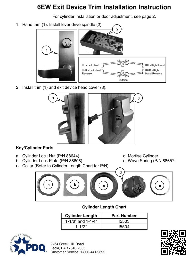
Turn the latch bolt
Attach the drill protection
Connection of ST550 / ST551 with STEP cable
Connection of ST550 / ST551 with separate cable
Activation of active signal
Cable dimensions
Initiation
Location of the strike plate
Content
Menu structure overview
1: Time & Date
2: Sync Mode
3: Door sensor
4: Timers Setup
5. Re-entry setup
6: Input setup
7: Relay setup
8: AUX Rel Menu
9: SSF3522
10: Service Due
11: FW ver menu
12: Factory Reset
13: Log Menu
14: Debug menu
Dimensions
Evacuation and re-entry
STEP Exit emergency device
Troubleshooting
Performance specications
Maintenance
Important information
Note of selected settings
Notes
Contact
3
3
3
4
5
6
6
6
6
6
7
7
7
7
8
8
8
8
8
9
9
9
9
9
10
10
11
12
12
12
13
14
15
15
15
16
17
18
18
18
19
19
20
21
22
23
23
24
24
24
24
25
26
26
27
27
28
28
29
30
31

3
ARTICLE NUMBER
ACCESSORIES
Accessories for ST550 and ST551
Art no. Description
ST500C STEP Control unit
ST1283 STEP Lead cover
ST0916 10 m cable 0,25 mm2 with 8 leaders.
ST0917 20 cm cable with adapter
ST1192 Skrew and magnet set.
ST1199 Drill protection
ST0918-1 Reinforcement plate with recess for cylinder. In polished stainless steel.
ST0918-2 Reinforcement plate with recess for cylinder. In brushed stainless steel.
ST0919-1 Reinforcement plate without recess for cylinder. In polished stainless steel.
ST0919-2 Reinforcement plate without recess for cylinder. In brushed stainless steel.
ST0910 Magnet
ST17999-70 Spindle 70 mm
ST17999-105 Spindle 105 mm
ST17999-140 Spindle 140 mm
ST17988-70 Cylinder spindle 70 mm
ST9009-15 Strike plate
Art no. Description
ST550 STEP 550 Motor lock. With modern bolt placement and latch lock. 50 mm back set.
ST550 KPL STEP 550 complete set. Incl. ST550, STEP Control unit, STEP Lead cover, 10 m cable, mechanical strike plate,
skrew and magnet set.
ST550 LB STEP 550 Lock and Control unit set. Incl. ST550, STEP Control unit, 20 cm cable and skrew set.
ST551 STEP 551 Motor lock. With modern bolt placement and latch lock. 50 mm back set.
ST551 KPL STEP 551 complete set. Incl. ST551, STEP Control unit, STEP Lead cover, 10 m cable, mechanical strike plate,
skrew and magnet set.
ST551 LB STEP 551 Lock and Control unit set. Incl. ST550, STEP Control unit, 20 cm cable and skrew set.
SPECIFICATIONS
Motor lock ST550 and ST551 certied according to SS-EN 14846:2008
1 2 3 4 5 6 7 8 9
Category
of use Durability and
load on latchbolt Door mass and
closing force
Suitability for
use on re/smoke
doors Safety Corrosion resistance,
temperature and humidity Security and
drill resistance
Security
electrical
function
Security
electrical
manipulation
3 X 9 F L 7 1 3
SSF 3522
Motor lock ST550 and ST551 certied
according to Class 5 SSF 3522 Edition. 2. CERTIFIERAD
Certicate C900547 | edition 1 | 2021

4
DIMENSIONAL DRAWING 550
DIMENSIONAL DRAWING 551
50
63
37
105
150
15,5
127
1666,5
75
19,5
22
14
203
225
50
63
37
150
15,5
127
75 19,5
22
203
225

54
CONTROL UNIT OVERVIEW ST500C
BOLT #1
LOCKED BOLT #1 OPEN BOLT #2
LOCKED BOLT #2 OPEN DOOR
OPEN/
CLOSED
LOCK
ALARM EXIT
ALARM AUX 4/
TAMPER
AUX 1 AUX 2 AUX 3
NO
COM
NC
NO
COM
NC
NO
COM
NC
NO
COM
NC
NO
COM
NO
COM
NO
COM
NO
COM
NO
COM
NO
COM
NO
COM
IN#1-
IN#1+
IN#2-
IN#2+
IN#3-
IN#3+
IN#5-
IN#5+
A+
B-
VCC
GND
IN#4-
IN#4+
A+
B-
VCC
GND
A+
B-
GND
OPEN#1 OPEN#2 EXT
DOOR
SENSOR
EXIT
RESET Electric
Lock 15-30V
AC/DC
AUX IN LOCK#1 LOCK#2 OSDP
-
GND
+
1 2 3 4 5 6 7 8 9 11
10
Input signal Description Function
IN#1 OPEN#1 Open signal lock 1
IN#2 OPEN#2 Open signal lock 2
IN#3 EXT DOOR SENSOR Extern door sensor
IN#4 EXIT RESET Reset alarm
IN#5 AUX IN Re-entry/Panic locking
LOCK#1 LOCK#1 Communication and voltage Lock 1
LOCK#2 LOCK#2 Communication and voltage Lock 2
OSDP OSDP OSDP-signal
Electric Lock Electric Lock Electric strike signal
GND GND Ground
AC/DC 15-30V AC/DC Supply voltage
Output signal Description Function
Relay #1 BOLT #1 LOCKED Bolt out and locked, Lock 1
Relay #2 BOLT #1 OPEN Bolt open, Lock 1
Relay #3 LOCK ALARM Communication alarm
Relay #4 BOLT #2 LOCKED Bolt out and locked, Lock 2
Relay #5 BOLT #2 OPEN Bolt open, Lock 2
Relay #6 DOOR OPEN/CLOSED Magnet
Relay #7 EXIT ALARM Manual unlocking
Relay #8 AUX 1 Programmable function
Relay #9 AUX 2 Programmable function
Relay #10 AUX 3 Programmable function
Relay #11 AUX 4/TAMPER Programmable function/Tamper

6
IN#1 OPEN#1 Öppnasignal lås 1
IN#2 OPEN#2 Öppnasignal lås 2
IN#3 EXT DOOR SENSOR Extern dörrmagnetsignal
IN#4 EXIT RESET Återställning larm
IN#5 AUX IN Re-entry/Paniklåsning
Open - Open signal
Activated by potential-free closing (default).
Can be changed to active.
OPEN # 1 Used to open lock 1 or lock 1 and
lock 2 in synchronized mode.
Open # 2 is only used to open
lock 2 in unsynchronized mode.
External door sensor - External door
magnet
Connection of external magnetic sensor for
door sensing. Can replace or be
combined with the internal door magnet.
Exit reset
For resetting the re-entry function. Used to
return to normal operation of the lock after
evacuation.
Reset can also be done via mechanical
cylinder.
AUX in - Re-entry function/Panic lock
Relay connection for re alarm or panic lock.
In the event of a re alarm, re-entry is
activated after passage. Applies to both
mechanical and electrical exit.
Panic lock function locks an unlocked door
and blocks unlocking. This feature overrides
the opening signal.
FEATURES CONTROL UNIT

76
LOCK#1
LOCK#1
Kommunikation och spänning Lås 1
LOCK#2
LOCK#2
Kommunikation och spänning Lås 2
OSDP
OSDP
OSDP signal
Electric Lock
Electric Lock
Elslutblecksignal
GND
GND
Jord
Lock - Communication and voltage
Connection of STEP motor lock
LOCK # 1 is used to connect lock 1.
LOCK # 2 is used to connect lock 2.
(It is possible to connect both locks
to LOCK # 1)
OSDP signal
Prepared for connection of OSDP signal.
Electric lock - Electrical end plate signal
Connection of STEP electric lock / electric
strike.
Controlled by OPEN # 1 and is activated as
long as the bolt is in.
The supply voltage to the control unit
also controls voltage to electrical strike.
GND
Connection of shielded cable.

8
Relay #1 BOLT #1 LOCKED Regel ute och förreglad, Lås 1
Relay #4 BOLT #2 LOCKED Regel ute och förreglad, Lås 2
Relay #2 BOLT #1 OPEN Regel inne, Lås 1
Relay #5 BOLT #2 OPEN Regel inne, Lås 2
Relay #3 LOCK ALARM Kommunikationslarm
Relay #6 DOOR OPEN/CLOSED Magnetkontakt
AC/DC 15-30V AC/DC Supply voltage
15-30V AC / DC - Supply voltage
Connection of supply voltage. The terminal is
potential-free and can be supplied with
15-30V AC / DC.
Bolt locked - Bolt out and locked
BOLT LOCKED activates relay when
the door is locked (bolt out and
locked).
BOLT # 1 LOCKED activates relay
from lock 1.
BOLT # 2 LOCKED activates relay
from lock 2.
Bolt open - Bolt in
BOLT OPEN activates relay when
the door is unlocked (Bolt in).
BOLT # 1 OPEN activates relay from
lock 1.
BOLT # 2 OPEN activates relay from
lock 2.
Lock alarm - Alarm in the event of a
malfunction
LOCK ALARM is activated at:
• Broken door
• Communication error / cable tampering
Prevented locking / unlocking
Restore to normal operation by repairing
the cause of the alarm or via EXIT RESET.
Door open / closed - Magnetic contact
DOOR OPEN / CLOSED activates the relay
for magnetic contact when the door is closed.

98
Relay #7 EXIT ALARM Manuell upplåsning
Relay #8 AUX 1 Programerbar funktion
Relay #9 AUX 2 Programerbar funktion
Relay #10 AUX 3
Programerbar funktion
Relay #11 AUX 4/TAMPER Programerbar funktion/Styrenhet öppnad
Exit alarm - Indication of mechanical unlocking
EXIT ALARM activates relay for unlocking via
key, cylinder knob or evacuation accessory
AUX 1 - Selectable function
AUX 1 activates the relay depending on func-
tion selection. The default is Vital
Closed (the door is closed and locked).
Selectable functions can be found on page
22 (8. AUX Rel menu)
AUX 2 - Selectable function
AUX 2 activates the relay depending on
function selection. The default is Vital open
(the lock is unlocked).
Selectable functions can be found on page
22 (8. AUX Rel menu)
AUX 3 - Selectable function
AUX 3 activates the relay depending on
function selection. The default is Service Due.
Selectable functions can be found on page
22 (8. AUX Rel menu)
AUX 4 / Tamper - Selectable function
AUX 4 / Tamper activates the relay depending
on function selection. The default is Tamper
(Sabotage contact control unit cover).
Selectable functions can be found on page
22 (8. AUX Rel menu)

10
TECHNICAL DATA
Security:
Grade 7 SS-EN 14846.
Class 5 SSF-3522.
Factory tested:
1 700 000 cycles
Fire approved:
E/EI 120 (ST550)
Certied according to:
SS-EN 179:2008
Certicate
• Certied in class 5 per SSF 3522.
• Certied in Grade 7 per SS-EN 14846.
• Certied in Grade M for corrosion, temperatures and humidity, which
corresponds to high requirements according to SS-EN 14846.
• Certied for re rated doors in Grade F (120 min) per SS-EN 14846: 2008.
Product characteristics
• Unlocks in less than 0.1 second.
• Modern bolt placement.
• The control unit handles day locking.
• Durable material choises with lock case in stainless steel.
• FreeDrive® technology.
• Manipulation-protected barrier technology.
• Back set 50 mm.
• Encrypted communication AES-128.
• Power consumption: 32 mA at rest, max 255 mA for about 20 ms.
• Guarantees opening even if the door is subjected to pressure of up to 5 kg.
• Connection to the motor lock is via RS-485.
• Prepared for OSDP.
• Evacuation and re-entry are ensured together with STEP Exit emergency exit
devices adapted for motor locks. Certied according to SS-EN 179:2008.
Environment
• The control unit can handle temperatures from -5 to +70 degrees.
• The lock can withstand temperatures from -20 to +70 degrees.
POWER CONSUMPTION
Power consumption
Voltage: 15-30 V AC/DC
Power consumption: 32 mA i vila, max 255 mA i ca 20 ms.

1110
COMPLETE SET
Picture no. Art no. Description
1 ST550 Motor lock
2 ST500C STEP Control unit
3 ST9009-15 Strike plate
4 ST0910 Magnet
5 ST1199 Drill protection
6 ST0917 20 cm cable with adapter
7 ST1192 Skrew and magnet set.
8 ST1283 STEP Lead cover
9 ST0916 10 m cable 0,25 mm2 with 8 leaders.
6
1
7
2
3
8
9
5
4

12
INSTALLATION INSTRUCTIONS
The latch bolt position
in a right handed door.
1. Pusch the latch bolt in.
2. Loosen the screw completely so that
the latch bolt is released.
1. Pull out and turn the latch bolt.
2. Put the latch bolt back. The latch bolt position
in a left handed door.
1. Pusch the latch bolt in.
2. Screw back the screw.
Turn the latch bolt for left handed doors (ST550)
The ST550 motor lock is delivered with the latch bolt mounted for a right handed door. If the lock
is going to be installed in a left handed door, the latch bolt must be turned.
Picture 1 Picture 2 Picture 3 Picture 4 Picture 5
Attach the drill
protection
Attach the drill protection with
included mounting pads.
Outside

1312
Connection of ST550 / ST551 with STEP cable (ST0916)
Connect supply voltage
Supply voltage must be connected to 15-30 V AC / DC. The terminal is polarity-free.
Connect opening signal
Open signal connects to OPEN # 1.
Art no. Description
ST550 STEP 550 Motor lock
ST0916 10 m cable 0,25 mm2 with 8 leaders.
ST500C STEP Control unit
Connect the pre-connected end of the cable to the back of
the lock. See picture.
Connect the other end of the cable to LOCK # 1 in the
control unit (lock 2 is connected to LOCK # 2). Check that
the leaders is connected as instructed.
Check that the switch on the back of the lock is set in its
upper position for lock 1 and its lower position for lock 2.
Switch Lock 1
Lock 2
1. Brown B-
2. White A+
3. Green VCC
4. Yellow GND
1. White A+
2. Brown B-
3. Green VCC
4. Yellow GND
1. IN#1-
2. IN#1+
OPEN #1
LOCK #1
15-30 V
AC/DC
Switch
Lock 1
Lock 2
Lock 1 Lock 2

14
Connect the connector of the cable adapter to the
back of the lock. See picture.
Pin and connect a separate extension cable.
Connect the cable to the white cable adapter.
Connect the other end of the cable to LOCK # 1 in the
control unit (lock 2 is connected to LOCK # 2). Check that
the leaders is connected as instructed.
Check that the switch on the back of the lock is set to
its upper position for lock 1 and its lower position for lock 2.
Connection of ST550 / ST551 with separate cable and adapter (ST0917)
Art no. Description
ST500C STEP Control unit
ST1283 STEP Lead cover
ST0916 10 m cable 0,25 mm2 with 8 leaders.
ST0917 20 cm cable with adapter
ST1192 Skrew and magnet set.
1. Brown B-
2. White A+
3. Green VCC
4. Yellow GND
1. White A+
2. Brown B-
3. Green VCC
4. Yellow GND
1. IN#1-
2. IN#1+
6. White A+
5. Brown B-
4. Green VCC
3. Yellow GND
OPEN #1
LOCK #1
15-30 V
AC/DC
Switch Lock 1
Lock 2
Lock 1
Connect supply voltage
Supply voltage must be connected to 15-30 V AC / DC. The terminal is polarity-free.
Connect opening signal
Open signal connects to OPEN # 1.

1514
ACTIVATION OF ACTIVE SIGNAL
The open signal inputs (IN # 1 and IN # 2) can be programmed to be activated by an active signal
or potential-free closing. Maximum voltage at active signal 30V, minimum 10V.
Potential-free closure is defult selected. See instructions on page 20.
INITIATION
Motor lock and control unit needs to be initialized. Follow these steps.
1. Connect the motor lock to ”LOCK # 1” on the
control unit. (If you have 2 locks the second lock is
connected to ”LOCK # 2”.)
2. Check that the switch in each lock is set to lock 1
and lock 2. Install lock in the door.
3. Power the control box.
4. Open the door, lock out the bolt via the cylinder.
(See Picture 1)
5. Press button . Connected locks are now initiated.
Picture 1
1
1
Display after pairing.
Display before pairing.
2
Drag in the bolt
Pull in the bolt manually via the cylinder or via the opening signal.
Close the door
Close the door and check that the latch bolt locks out again (default delay 0.5 sec). If the door is not
opened after the opening signal has been given, the motor lock re-locks again after a preset delay
of 3 sec. (Delay times can be adjusted in the ”time setup” menu).
The display will show ”searching” for 5
min. When lock 1 and the control unit
are paired , appears at the
bottom left of the display. The search
can be canceled by pressing
button again.
When lock 2 and the control unit are
paired , appears at the bottom
right of the display.
2
1
CABLE DIMENSIONS
Cable length Cable area at 24V
20 m 0,3 mm2
30 m 0,4 mm2
40 m 0,5 mm2
50 m 0,6 mm2
Squeeze the connector to
release the cable.
Disassembly of cable
Safe mode
1

16
Applies when using the motor lock’s internal magnetic contact.
LOCATION OF THE STRIKE PLATE
The motor locks’s door monitor is placed behind the plate at the sensor marking:
1. Install the supplied magnetic contact in the strike plate. It is important that the
magnetic contact in the strike plate and the sensor marking on the plate is placed
at the same height.
2. Make sure that there is no preload on the hook bolt.

1716
MENU STRUCTURE OVERVIEW
Settings
13: Log Menu
1: Time & Date
5. Re-entry setup
4: Timers Setup
3: Door sensor
7: Relay setup
6: Input setup
2: Sync Mode
12: Factory Reset
14: Debug menu
11: FW ver menu
9: SSF3522
8: AUX Rel Menu
10: Service Due
13.1: Record #1-10
1.1: Date
1.2: Time
5.1: Re-entry Mode
3.1: Mode: Internal/External
7.1: Relay #1-11
4.1: Open timer
4.2: Deadbolt
4.3: Door alarm
6.1: Input 1-5
2.1: Sync Mode: ON/OFF
12.1: Delete settings
9.1: Timer Mode
8.1: AUX 1-4 Relay
10.1: Mode
10.1.1: Cycles
10.1.2: Date

18
3: Door sensor
Setting for which door sensor or magnetic contact that is useed.
3.1: Mode: Internal/External (Default Internal)
Choose between internal, external or both
internal and external door magnet.
Change with .
Internal
External
Door
sensor
Internal & External
1: Time & Date
Time is preset to GMT + 1. Time and date can
be changed in separate submenus.
1.1: Date
Current date (DD.MM.YYYY).
Change date: press , change with .
Conrm with .
1.2: Time
Current time, 24 hours (HH: MM).
Change time: press , change with .
Conrm with .
Date
Time
Time & Date DD.MM.YYYY
HH:MM
2: Sync Mode
Activate synchronization mode for 2 locks where
both locks are controlled by OPEN # 1. Change with
2.1: Sync Mode: ON/OFF (förinställt OFF)
ON: Aktivera synkronisering
OFF: Avaktivera synkronisering
ON
OFF
Sync Mode

1918
4: Timers Setup
Settings for operating times.
4.1: Open timer (Default 3 s)
Setting for unlocked time. The opening time can
be set between 3-30 seconds.
Change setting: press , change with .
Conrm with .
4.2: Deadbolt (Default 3 s)
Time setting for delay of locking out
the deadbolt after contact with the door
magnet. Can be set between 0-10 seconds.
Change setting: press , change with .
Conrm with .
4.3: Door alarm (Default OFF)
Time setting for a door buzzer function.
Can be set between OFF / 15-180 seconds.
Change setting: press , change with .
Conrm with .
(Must be supplemented with AUX setting,
8: AUX Rel Menu, page 22).
Open timer
Deadbolt
Timer
setup
Door open
3-30 s
0-10s
OFF/15-180s
5. Re-entry setup
Settings for evacuation and re-entry.
5.1: Re-entry Mode (Default OFF)
Enable or disable re-entry.
Re-entry is activated (ON), deactivated
(OFF) or time activated (3-60 min).
Select mode with .
Change the setting to time: press , change
with . Conrm with .
ON
OFF
Escape
Mode
3-60 min

20
6.1: Input 1-5
6: Input setup
Input settings.
Scroll between inputs with .
Change the setting with .
Mode relay or AC/DC
Choose passive (Relay) or active (AC/DC).
Potential
Relay no. Description Programming
IN #1 polarity OPEN #1 HIGH or LOW
IN #2 polarity OPEN #2 HIGH or LOW
IN #3 polarity DOOR SENSOR HIGH or LOW
IN #4 polarity EXIT RESET HIGH or LOW
IN #5 polarity AUX IN HIGH or LOW
Relay no. Description Programming
IN #1 mode OPEN #1 RELAY or AC/DC 10-48V
IN #2 mode OPEN #2 RELAY or AC/DC 10-48V
IN #3 mode DOOR SENSOR RELAY
IN #4 mode EXIT RESET RELAY
IN #5 mode AUX IN RELAY
Polarity: HIGH/LOW
Choose closed or open. Potential free.
IN #1 polarity HIGH
LOW
Input #1 mode Relay
AC/DC
IN #2 polarity HIGH
LOW
Input #2 mode Relay
AC/DC
IN #3 polarity HIGH
LOW
Input #3 mode Relay
IN #4 polarity HIGH
LOW
Input #4 mode Relay
IN #5 polarity HIGH
LOW
Input #5 mode Relay
Input #5 Role Fire
Panic
Input
setup
This manual suits for next models
1
Table of contents
