Digitronic CamCon DAC16 User manual
Digital-Analog-Converter
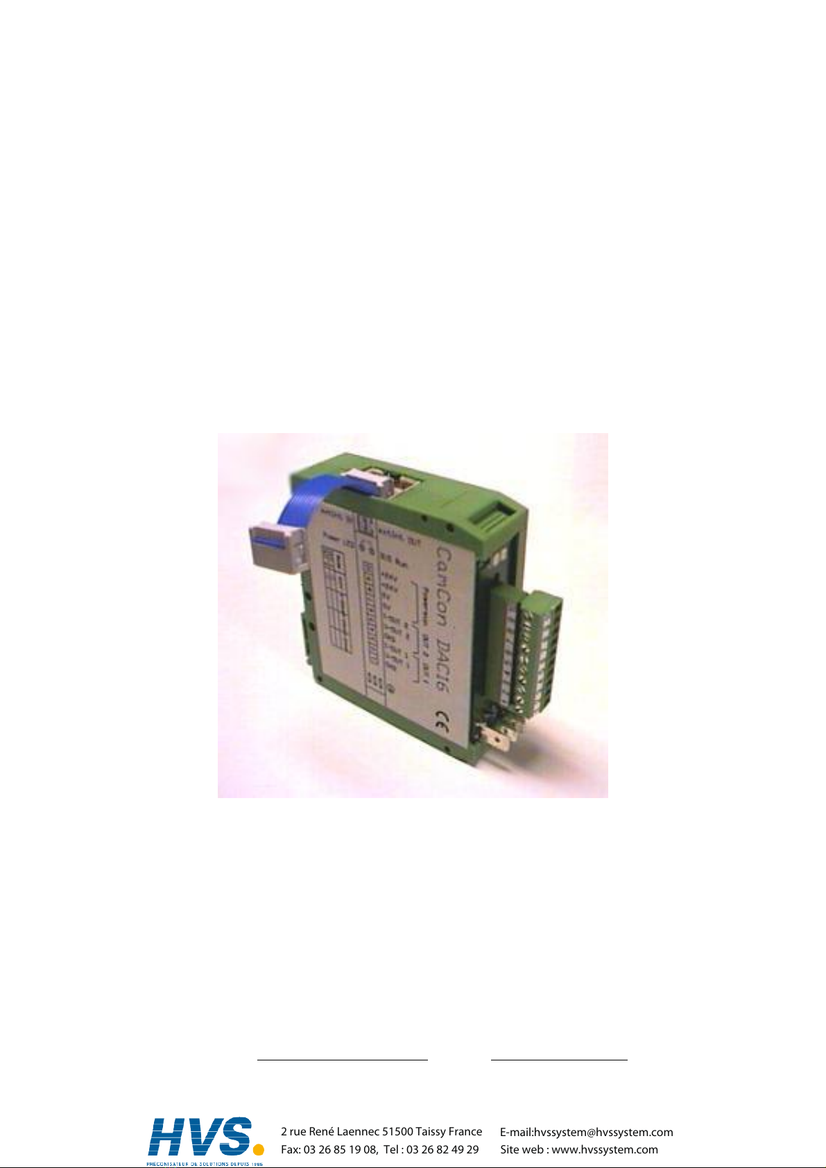
CamConDAC16
DigitronicAutomationsanlagen GmbH
Steinbeisstraße 3
•
D -72636 Frickenhausen
•
Tel. (+49)7022/40590-0
•
Fax -10
Auf derLangwies 1
•
D -65510 Hünstetten-Wallbach
•
Tel.(+49)6126/9453-0
•
Fax -42
Internet: http://www.digitronic.com
•
E-Mail: mail@digitronic.com
2 rue René Laennec 51500 Taissy France
Fax: 03 26 85 19 08, Tel : 03 26 82 49 29
E-mail:[email protected]
Site web : www.hvssystem.com

Digitronic Digital-Analog-Converter
AutomationsanlagenGmbH CamCon DAC16
Foryourattention
Thisinstruction manualrelatesto the CamCon DAC16 from28.11.1997. The companyDigitronic
Automationsanlagen GmbH reservesthe right to makechangeswhichpresent an improvement ofthe
qualityorfunctionalityofthe devicewithout priornotice. The instruction manualwascreated with great
care, although itmaynot be error-proof.Wewouldbe gratefulforanycommunication relating to any
errors you mayhave found.
UP-date
You can alsoobtainthisinstruction manualon the Internet at http://www.digitronic.com inthe latest
version asPDFfile.
Qualifiedpersonnel
Thisdevicemayonlybe started and operated byqualified staff.Byqualified wemean personnelwho
areentitled to handle, to earth and to labledevices,systemsand powercircuitsinaccordancewith the
technologysafetystandards.
Liability
(1)The supplierisliablefordamagescaused byhimselforbythe ownerofthe rightsup to the sumof
the salesprice. He isnot liableforloss ofprofits,forfeited savings,intermediate and successive
damages.
(2)The abovementioned limitsto liabilitydo not applyto insuranceofnamed characteristics and
damageswhich were caused deliberatelyorthrough negligence.
Protection
The CamCon DAC16 and thisinstruction manualareprotected bycopyright. All rightsarereserved.
Neitherthe CamCon DAC16, northisdocument maybe copied asawholeorpartially,photocopied,
reproduced, translated ortransferred to electronicmediaofanykind orinto machine readableformat
without priorwritten permission bythe companyDigitronicAutomationsanlagen GmbH.
Note: Wehaveexamined the devicesofthe CamCon seriesforyear2000 compatibilityand
have not found anyadverse effectson anyfunctions.
Note: CamCon isaregistered trademarkofthe companyFirmaDigitronic
Automationsanlagen GmbH.
Note: The devicesofthe CamCon seriescomplywith the standardsforelectromagnetic
compatibility:EN 55011, EN 55022, EN 55024 Part 2, EN 50082 Part 2, ENV50140,
VDE0843 Part 2, VDE0843 Part 4, VDE0871, VDE0875 Part 3 ("N"),
VDE0875 Part 11, VDE0877 Part 2, IEC 801 Part 3, IEC 801 Part 2, IEC 801 Part 4,
IEC 801 Part 5.
(c) Copyright 1992 -2004 / File: DAC16E.DOC
DigitronicAutomationsanlagen GmbH
AufderLangwies1
D-65510 Hünstetten -Wallbach
Tel. (+49)6126/9453-0 Fax. (+49)6126/9453-42
Internet: http://www.digitronic.com
E-Mail: mail@digitronic.com
Edition: Aug. 04 Page: 2
2 rue René Laennec 51500 Taissy France
Fax: 03 26 85 19 08, Tel : 03 26 82 49 29
E-mail:[email protected]
Site web : www.hvssystem.com

Digitronic Digital-Analog-Converter
AutomationsanlagenGmbH CamCon DAC16
Table of contents
1. Introduction..........................................................................................................................................3
2. Assembling ..........................................................................................................................................4
3. StatusLED´s........................................................................................................................................4
4. Dimensions..........................................................................................................................................4
5. Electricalconnections..........................................................................................................................5
5.1. Terminalallocation............................................................................................................................5
5.1.1. Terminalallocation ofthe supplyvoltage.......................................................................................5
5.1.2. Terminalallocation ofthe analog input 1.......................................................................................5
5.1.3. Terminalallocation ofthe analog input 2.......................................................................................5
5.2. Externalinterface..............................................................................................................................5
5.2.1. Pin allocation ofthe externalinterface IN......................................................................................5
5.2.2. Pin allocation ofthe externalinterface OUT..................................................................................5
5.2.3. Externalinterface with a wiring distance of0.5 up to 300m...........................................................6
6. The analog outputs..............................................................................................................................6
6.1. Signallevelofthe analog outputs.....................................................................................................6
7. Commisioning......................................................................................................................................6
8. Technicaldata......................................................................................................................................7
1. Introduction
The digital-analog -converterCamCon DAC16 isused asan anlog output expansion forelectronic
camswitchesofthe CamCon series.Theyareableto put out e.g. the speed, positiopn orvaluesfor
Camsviatheirexternalinterface. Ifusing aaCamCon DAC16 converterinstead ofan ordinaryoutput
module(e.g. DC91I/OorDC16I/O),the parallelbinarysignalget converted into analog signals.Every
CamCon DAC16 modulehastwo16Bitanalog outputsthat can provide current-aswell asvoltage
signals.Inputsarenot avaiable. Byserialswitching ofseveralCamCon DAC16 modules,itispossible
to expand the numberofmodulesto amaximumof13. Thisprovidese.g. foraCamCon DC16 up to
26 analog Cam-outputs.
Edition: Aug. 04 Page: 3
2 rue René Laennec 51500 Taissy France
Fax: 03 26 85 19 08, Tel : 03 26 82 49 29
E-mail:[email protected]
Site web : www.hvssystem.com

Digitronic Digital-Analog-Converter
AutomationsanlagenGmbH CamCon DAC16
2. Assembling
The D/AconverterDAC16 issnapped onto an "EN-carrier-rail" inthe switchchest. Toprotectthe
modulefromoverheating, itisnecessaryto leaveagap ofat least10mm between the devices.The
grounding clampsareto be connected on the shortestpossiblewaywith the centralgrounding point of
the assembling plate. The CamCon DC16'sexternalinterfaceisconnected with the ten polemaleplug
"ext.Int.IN" of the CamCon DAC16 I/Omoduleusing the enclosed 10 poleflatwirecable. Everyfurther
CamCon DAC16 moduleisconnected using the enclosed 10 poleflatwirecableto the ten polemale
plug "ext.Int.IN" ofthe CamCon DAC16 I/Omodule. Ifinaddition to the CamCon DAC16 modulea
CamCon DC16/IOmodule isused, the DAC16 module hasto be switched to the end ofthisrow.
The voltage supplyhasto be connected to everyDAC16 module. It hasavoltage of24VDC +/-20%.
The data-linesofthe CamCon DAC16 modulesareconnected to eachotherviaopticalcouplers and
thereforepotentiallyfree. The wiring ofthe analog outputshasto be done using shielded cables,the
shield hasto be laid to the grounding plug on one side. All wiring hasto be done in cold state.
3. StatusLED´s
The D/AconverterDAC16 hastwo statusLEDs:
LED yellow:supplyvoltage ispresent.
LED Red: indicates,that no data exchange viaaCamCon DC16 takesplaceat the moment.
Possiblescausesare: The cablelength adjusted at the CamCon outrunsthe maximum
length of300 meters,the CamCon DC50, 90 orDC115 isswitched off,i.e. the data
exchange isinterrupted (broken wire).
4. Dimensions
Edition: Aug. 04 Page: 4
2 rue René Laennec 51500 Taissy France
Fax: 03 26 85 19 08, Tel : 03 26 82 49 29
E-mail:[email protected]
Site web : www.hvssystem.com

Digitronic Digital-Analog-Converter
AutomationsanlagenGmbH CamCon DAC16
5. Electrical connections
.5.1. Terminal allocation
.
5.1.1. Terminal allocation of thesupplyvoltage
Terminal 7: 0Vsupplyvoltage
Terminal 8: 0Vsupplyvoltage
Terminal 9: +24VDC supplyvoltage
Terminal10: +24VDC supplyvoltage
5.1.2. Terminal allocation of theanalog input 1
Terminal 1: GND reference potential(0V)
Terminal 2: voltage output +/-10Volt maximum10mA.
Terminal 3: current output 0-20mA, 4-20mAor0-24mA.
beiRL maximum550Ω
5.1.3. Terminal allocation of theanalog input 2
Terminal 4: GND reference potential(0V).
Terminal 5: voltage output+/-10Volt maximum10mA.
Terminal 6: current output 0-20mA, 4-20mAor0-24mA.
at RL maximum550Ω
Note:Terminal1, 4, 7 and 8 are connected to each other.
5.2. External interface
Viathe externalinterfacethe data exchange with the CamCon camswitchtakesplace. The CamCon
DAC16 Modulehastwo10 polemaleplugs,called "ext.Int.IN" and "ext.Int.OUT" connection. Viathe
ext.Int.OUTthe data exchange with afurtherCamCon module(e.g. CamCon DAC16, CamCon
DC16I/OorCamCon DC91I/Oi.e. DC92/I).The data exchange isrealised viaopticalcouplers and
thereforethe connection remainsfree of potentials.Bythiswayof switching aBUSsystem fordifferent
applicationscan be established. Forthe connection ofthe DAC16 module with the CamCon DC16 a 10
pole flatwire cable isenclosed.
DAC16 DC16 5.2.1. Pinallocation of theexternal interface IN
Pin 1,10: not used
Pin 4,7: ground (0V)
Pin 2: RxD-
Pin 3: RxD+
Pin 5: CLK-
Pin 6: CLK+
Pin 8: TxD-
Pin 9: TxD+
5.2.2. Pinallocation of theexternal interface OUT
Pin 1,4,7,10: not used
Pin 2: TxD-
Pin 3: TxD+
Pin 5: CLK-
Pin 6: CLK+
Pin 8: RxD-
Pin 9: RxD+
Edition: Aug. 04 Page: 5
2 rue René Laennec 51500 Taissy France
Fax: 03 26 85 19 08, Tel : 03 26 82 49 29
E-mail:[email protected]
Site web : www.hvssystem.com

Digitronic Digital-Analog-Converter
AutomationsanlagenGmbH CamCon DAC16
5.2.3. External interface withawiring distance of 0.5up to300m
The maximumwiring distanceofthe externalinterfaceis300 meters.Forthispurposea6poledata
cablewith conductors wired aspairs isrequired aswell asan adaptercablefrom10 poleflatwireto 9
pole D-Sub-plug. Thiscable'sshielding hasto be laid to the grounding plugson both sides.
6. Theanalog outputs
The CamCon DAC16 hastwo 16 Bit analog outputs. Theyprovide either0 -20mA,4-20mA,0 -24mA
or,asan option, +/-10Voltsignals.The maximum output current at +/-10 Voltis10mA(not shortcircuit
proof). The load-resistance undercurrent-output must not outrun 550Ω. The outputsarenot potentially
free towardsthe voltage supply.the wiring ofthe analog outputshasto be done using shielded cables
and the cable'sshielding hasto be laid to the grounding plugson one side.
6.1. Signal level of theanalog outputs
The CamCon DAC16 moduleoffers 4possibilitiesofsignaloutput forboth analog outputs.Theseare:
0 -20mA, 4 -20mA, 0 -24mAoroptionaly+/-10Volt.
The adjusted signallevelsarefactory-provided marked byacross at
the stickerlabelon the left side ofthe case.
OUT2
OUT1
Ifyou want to change the signallevel,the devicehasto
be opened. The casecan be opened inthe middle
using ascrewdriver.Onthe solding side ofthe largest
printed circuitboardtwosolding bridgesforevery
analog output, i.e. the analog output 1(OUT1)and 2
(OUT2),arelocated, whicharenamed J1to J4inthe
drawing to the right. J1and J2areused to adjustthe
signallevelforoutput 1and J3and J4to adjustthe
output levelforoutput 2.
The drawing to the right shows
whichsolding bridgeshaveto be
opened orclosed, to get the
desired signallevel.
Note:
Forthe +/-10Voltvoltage output an daditiona
lsmall wrapped printed circuit board isrequired.
7. Commisioning
Beforethe firstcommisioning, checkthe device'swiring carefully.See alsochapter5. Electrical
connectionson page 5. Forconfiguration and calibration ofthe analog outputspleaseregardinthe
camswitchesmanualthe chapter"unitconfiguration",sub-chapter"anolog outputs"and inthe chapter
"systemconfiguration"sub-chapter"specialoutputs".
Edition: Aug. 04 Page: 6
2 rue René Laennec 51500 Taissy France
Fax: 03 26 85 19 08, Tel : 03 26 82 49 29
E-mail:[email protected]
Site web : www.hvssystem.com

Digitronic Digital-Analog-Converter
AutomationsanlagenGmbH CamCon DAC16
8. Technical data
Display ................................................................2 StatusLED´s forsupplyvoltage and errormessages
Numberofoutputs ..............................................two 16 Bit analog outputs.
Type ofoutput.....................................................Poweroroptionallyvoltage.
Current output.....................................................optionally0 -20mA, 4 -20mAor0 -24mA
at RL maximum550Ω.
Voltage output.....................................................+/-10Volt up to 10mA(not short circuit proof)
Resolution...........................................................16Bit.
Maximumresponse time with full levellift............approximately3ms.
Length ofthe connection cable
between CamConDC16 and CamCon DAC16...maximum300m.
Supplyvoltage.....................................................24VDC ±20 %
Powerconsumption ............................................approximately60mAwithout load.
Connectionsfor:
Voltage supplyand outputs ................................via plug-in screwclampsIP20
Assembling .........................................................comfortablesnap-on assembling, carrierrail according
to EN50 022, maybe set inrowswith 10mm gap for
aircirculation
Disassembling.....................................................bypulling backthe snap-bars.
Dimensions.........................................................See chapter4. Dimensionson page 4.
Protection............................................................Case correspondsto IP20.
Working temperature..........................................0°C ... +50°C
Weight.................................................................approximately150g
Edition: Aug. 04 Page: 7
2 rue René Laennec 51500 Taissy France
Fax: 03 26 85 19 08, Tel : 03 26 82 49 29
E-mail:[email protected]
Site web : www.hvssystem.com
Table of contents
Other Digitronic Media Converter manuals

Popular Media Converter manuals by other brands


AFi
AFi MX1M-FX-SC MX 1MSeries Installation and operation manual

Bonart
Bonart ART Marquee ART-M3II instruction manual

WoMaster
WoMaster DS101 Quick installation guide

RKC INSTRUMENT
RKC INSTRUMENT COM-JC Quick instruction manual

Renishaw
Renishaw RGH40 RESR40 installation guide

Intermec
Intermec DC-DC installation instructions