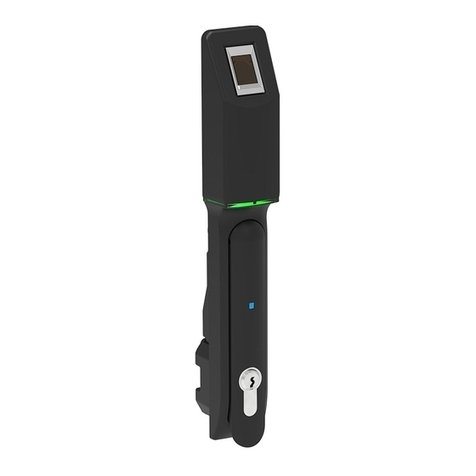
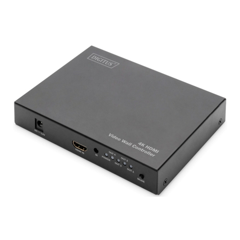
Digitus dbSentry Assembly instructions

Document Ref
DOC-200053r003
Document T
itle
dbSentry Hardware Installation Manual
Page
1 of 11
Document Information
Reference
SR
-
2
000
53
Title
dbSentry Hardware Installation Manual
Synopsis
Document Synopsis
Author
David Montgomery
Creation Date
20
20
-
Jan
-
17
Revisions
Rev
Date
Who
Notes
00
1
20
15
-
Feb
-
26
Chris Marsden
Initial document
002
201
5
-
Feb
-
27
Chris Marsden
pdated
003
2020
-
Jan
-
17
David Montgomery
Convert to Digitus Document Standard
and update
This manual, as well as the software described in it, is furnished under license and may be used or copied only in
accordance with the term of such license. The content of this manual is furnished for informational use only, is subject to
change without notice, and should not be construed as a commitment by Digitus Biometrics, Inc. (Digitus). Digitus assumes
no responsibility or liability for any errors or inaccuracies that may appear in this documentation. Except as permitted by
such license, no part of this publication may be reproduced, stored in a retrieval system, or transmitted, in any form or by
any means, electronic, mechanical, recording, or otherwise, without the prior written permission of Digitus.
©2005-2020 Digitus Biometrics, Inc. All rights reserved.

Document Ref
DOC-200053r003
Document T
itle
dbSentry Hardware Installation Manual
Page
2 of 11
Contents
dbSentry Overview ............................................................................................................................................................... 3
Installing the dbSentry Controller ...................................................................................................................................... 4
dbSentry Sensor / Wiegand Connector Pinout ................................................................................................................... 5
Installing the Door Contacts ................................................................................................................................................ 6
Installing the Tamper Inputs ............................................................................................................................................... 7
Wiegand Output .................................................................................................................................................................. 8
Attaching Lock Devices ....................................................................................................................................................... 9
dbSentry Dev1 / Dev2 Pinout .............................................................................................................................................. 9
Network/PoE Switch Connection ...................................................................................................................................... 10
Connecting External / Auxiliary Power ............................................................................................................................. 11

Document Ref
DOC-200053r003
Document T
itle
dbSentry Hardware Installation Manual
Page
3 of 11
dbSentry Overview
The dbSentry Controller provides an extremely effective way to secure access to data cabinets and is particularly suited
to:
Low volume environments
Dispersed environments
Low density environments
Where a PoE solution is required
Where inter-connections between cabinets is not permitted
Figure 1
–
db Sentry
The controller is very compact in size, measuring just 4” x 2” x 1” (10.2cm x 5.1cm x 2.6cm).
It can be powered via Power over Ethernet (PoE), an external power supply, or both (with the PoE connection being the
primary and the external power supply being the secondary / backup).
The dbSentry Controller can also be integrated with third-party access control systems, using its Wiegand output and is
compatible with many third-party software platforms at the software level.

Document Ref
DOC-200053r003
Document T
itle
dbSentry Hardware Installation Manual
Page
4 of 11
Installing the dbSentry Controller
The dbSentry Controller is very small and compact in size, measuring just 4” x 2” x 1” (10.2cm x 5.1cm x 2.6cm).
It can be installed anywhere in the cabinet and can be attached using the VHB tape strip (supplied).
Figure
2
–
dbSentry Sensor / Wiegand and Network / PoE connectors
Figure
3
–
External power and devices (handle) connectors
It is important to record the IP
and
MAC address
es,
and location of each dbSentry Controller.
The MAC address is used hen identifying each unit ithin the Digitus DAS-SQL soft are.

Document Ref
DOC-200053r003
Document T
itle
dbSentry Hardware Installation Manual
Page
5 of 11
dbSentry Sensor / Wiegand Connector Pinout
Figure
4
–
dbSentry Sensor / Weigand Connector pinout
Top of dbSentry
Controller

Document Ref
DOC-200053r003
Document T
itle
dbSentry Hardware Installation Manual
Page
6 of 11
Installing the Door Contacts
For each device (Dev 1/Dev 2) on a dbSentry Controller, a set of Door Contacts can be installed. The Door Contacts will
allow the position of the door (open/closed) to be monitored.
Figure
5
-
Dev 1
Door Contacts
Figure
6
-
Dev 2
Door Contacts
Figure
7
–
Door
Contact location on cabinet
se the Digitus supplied Door Contacts only.
Do not use ordinary reed switches as these will cause the device to go into an alarm condition.

Document Ref
DOC-200053r003
Document T
itle
dbSentry Hardware Installation Manual
Page
7 of 11
Installing the Tamper Inputs
For each device (Dev 1/Dev 2) on a dbSentry Controller, a set of tamper switches can be installed.
The tamper switches can be used on side/top panels of a cabinet, creating an immediate alarm If the tamper switch
opens.
Figure
8
-
Dev 1
Tamper Input
Figure
9
-
Dev
2
Tamper Input
se Digitus supplied Tamper Switches only.
Do not use ordinary reed switches as these will cause the device to go into an alarm condition.

Document Ref
DOC-200053r003
Document T
itle
dbSentry Hardware Installation Manual
Page
8 of 11
Wiegand Output
The dbSentry Controller offers two separate Wiegand outputs (one for each device), allowing for seamless integration
into third-party Access Control Systems.
The Wiegand data format is very flexible, and is configured via the Digitus DAS-SQL software platform.
The diagram shows how to connect a control unit to a third-party system.
Note the two Wiegand outputs share a common ground (GND) connection.
Figure 1
0
-
Wiegand Output for Device 1
Figure 1
1
-
Wiegand Output for Device 2

Document Ref
DOC-200053r003
Document T
itle
dbSentry Hardware Installation Manual
Page
9 of 11
Attaching Lock De ices
Lock devices (or handles) are connected to the dbSentry Controller using the Dev1 and Dev2 sockets shown in the
diagram below.
Each dbSentry Controller has two device inputs, Dev 1 and Dev 2.
Figure 1
2
–
the Dev1 & Dev2 ports
Instructions for the installation of the actual devices (handles) are included with the devices.
dbSentry De 1 / De 2 Pinout
Figure 1
3
–
dbSentry Dev1 / Dev2 Pinout
Dev 1
Dev 2
Aux.

Document Ref
DOC-200053r003
Document T
itle
dbSentry Hardware Installation Manual
Page
10 of 11
Network/PoE Switch Connection
Connect a network cable to the dbSentry Controller Network/PoE port as shown below. If you are using Power over
Ethernet (PoE) this will also provide power to the dbSentry Controller.
The dbSentry Controller uses <0.03A at 48V.
Figure 1
4
–
the Network / PoE port

Document Ref
DOC-200053r003
Document T
itle
dbSentry Hardware Installation Manual
Page
11 of 11
Connecting External / Auxiliary Power
The dbSentry Controller will also support an external / auxiliary power supply (sold separately). This can be used in the
following situations:
•If PoE is not available.
•As a backup or redundant power supply to the PoE. If power from the PoE connection is lost, the auxiliary power
supply will automatically kick in.
Connect the auxiliary power supply as shown below.
Figure 1
5
–
Connecting external / auxiliary power
** An auxiliary po er supply can be purchased from Digitus Biometrics by referencing part code dbPo er **
** Please note that using a non-approved external / auxiliary po er supply ill void the product arranty **
Table of contents
Other Digitus Controllers manuals
Popular Controllers manuals by other brands

Desert Aire
Desert Aire CM3560 Series Installation and operation manual

Software House
Software House iSTAR Ultra Hardware installation

Danfoss
Danfoss Cascade HFC Application guide

Jaga
Jaga JDPC.001 Installation and user guide

Bang & Olufsen
Bang & Olufsen LC2 user guide

Omron
Omron SYSMAC NY Series Hardware user manual

Bartlett
Bartlett Boss Series manual

Arlight
Arlight LT3200-350 quick start guide

Pfeiffer Vacuum
Pfeiffer Vacuum TPG 300 operating instructions

Sentera Controls
Sentera Controls GTTE1 Mounting and operating instructions

Allen-Bradley
Allen-Bradley PowerFlex 700S Original instructions

Thrustmaster
Thrustmaster eswap X quick start guide