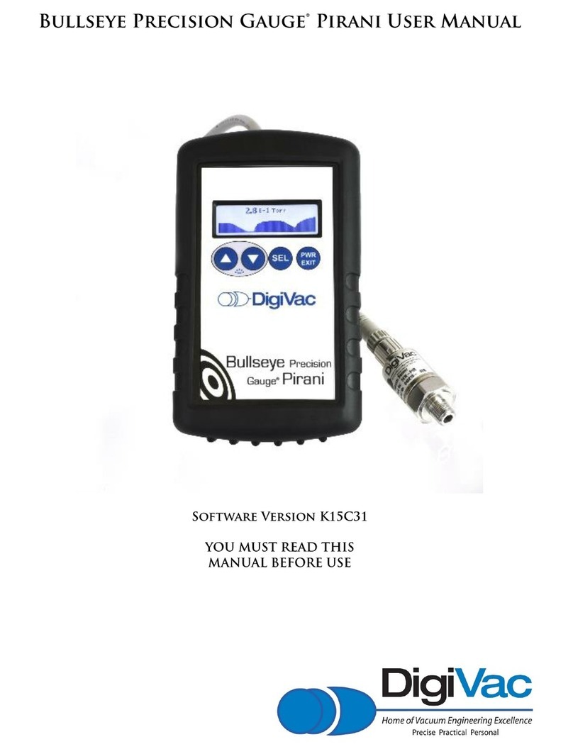
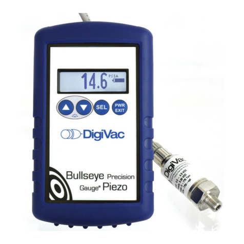
DigiVac Bullseye Precision Gauge Piezo User manual


3
The Bullseye Precision Gauge Piezo was developed to make vacuum measurement easy, useful
and intuitive. The Bullseye Piezo is a rugged portable vacuum instrument that is sensitive and
highly accurate. It was designed to suit the demands of field use. It’s amazing. Its main
features include a graphical LCD display with a white backlight for showing large numerical
fonts and digital graphics to show line graphs and time horizons of data from 1 minute to 1
hour. This graphical display of vacuum pressure makes understanding system trends easy by
showing points of inflection and small changes in pressure with sub second resolution.
•Rugged design for field or laboratory use
•Dimensions: 6.2” x 3.7” x 1.3”
•Only requires 4 AA alkaline or Micro-B USB
•Range of 1 to 775 Torr, -29.92 to 0.59 inches Hg, and mbar
•+/- 2 Torr, +/- 0.08 inches Hg Accuracy
•Numerical graphing display
•Resolution of +/- 0.1 Torr, +/- 0.01 inches Hg
•12 Units: microns, millitorr, Torr, mbar, Bar, kPa, pascals, PSIA, mmHg, inHg, mmH2O,
inH2O
•Isolated sensor –Low risk of sensor contamination
•Battery life of 2800mah/25ma, or 127 hours ~ 5 days
•Vacuum Interface of ⅛” NPT male or PTFE hose barb, KF16, KF25
•CE & RoHS compliant
•Simple, easy-to-use design
•On/Off soft switch
•LCD graphical, white backlight, sunlight readable
•Large numerical font
•Digital graphics to display line graphs and time horizons of 1 minute and 1 hour
•7-foot sensor cable length
•Sensor electrical interface: M12
•Magnet

4
While this vacuum instrument has many features, it is very simple to use. Start by unpacking
the unit to verify you've received everything you've ordered.
•Vacuum instrument with white backlight and purple rubber boot
•Attached: 7' sensor cable with keyed connector designed to thread directly into the
sensor
•Piezo vacuum sensor and PTFE hose adapter
•Quick Start guide or (this) user manual
•Remove protective boot
•Remove the battery cover and install 4 AA batteries or attach a Micro-B USB
•Plumb Piezo vacuum sensor into the system to be measured, taking care to
differentiate between the threaded end and the end connecting the sensor to the cable
•Thread sensor cable into sensor (cable connector is keyed)
•Power on the device by pressing the PWR/EXIT button. It will take about 5 seconds to
fully power up and for the reading to settle.
•If need be, turn on the backlight. The backlight does not affect gauge reading or
accuracy.
•Read vacuum!

5

6
The Bullseye Precision Gauge Piezo incorporates an isolated Piezo resistive sensor. A piezo
resistive sensor is effectively a silicon strain gauge. When the pressure is placed upon the
silicon, the resistance of a MEMS measurement resistor changes which can be measured by
the sensor electronics. The sensor itself incorporates a wheatstone bridge that is very
sensitive to absolute pressure levels from 1 Torr = 1 mbar to 775 Torr = 1033 mbar. Piezo
resistive sensors are often referred by their full scale or maximum pressure that they measure.
For example, our 775i sensor has a maximum pressure sensitivity of 775 Torr or 15PSIA. There
are other piezo-resistive types of sensors that are sensitive in other pressure levels. Other
pressure levels that are common with piezo resistive sensors are 30 PSI, 100 PSI, 200 PSI and
1000 PSI.
Piezoresistive sensors have exceptional durability combined with low cost and better than 1%
full scale accuracy. They are chosen when a combination of durability, cost and accuracy are
all important.
The accuracy of a piezo resistive sensors are typically given in % of full scale. For example, a
100 PSI piezo sensor that is 1% accurate would have an accuracy of ± 0.01 * 100 PSI or ± 1
PSI. Note this makes the % of reading accuracy very good near its full range of 100 PSI, but
not so good near its base pressure (lowest detectable pressure) of 1 PSI. The 775i sensor has
an accuracy of ± 2 Torr, or 0.25% of full scale. This would make it’s accuracy at 10 Torr ± 2/10
or ± 20% of reading at an actual pressure of 10 Torr; and at 200 Torr, ± 2/200 or 1% of
reading.
The most important thing about accuracy is knowing what you need for your process. Do you
really care about the difference between 100 Torr and 102 Torr? All sensors have trade offs of
cost and convenience. There is a tendency of us science types to demand the best most
accurate instruments. However, if our process doesn’t require the best accuracy available, it
may be more efficient to do work with a gauge that is slightly less accurate but more robust.
For example, a more accurate alternative to the Bullseye Piezo is a 1000 Torr capacitance
manometer. Some can be had at 0.15% of reading, and are also isolated. However, they tend
to be expensive, don’t travel well (easily damaged), and require frequent maintenance to
maintain that accuracy, especially around 10 Torr. The Bullseye Precision Gauge Piezo was
built from the ground up to be rugged and thrive with field use.
The isolated part of the sensor is important. Isolated means that the sensing electronics are
separated and protected from the process gas pressure being measured. Who cares? When
measuring clean dry gasses, isolated doesn’t matter. Non-isolated sensors where the silicon
die of the piezo resistive would come in contact with clean dry gasses like air and nitrogen
work just fine. These electronics can survive a lifetime exposed to clean dry air and even low
humidity and an occasional splash of water (when not energized). Corrosive gasses on the
other hand will corrode the silicon die and wires that make up a sensor just like the ocean

7
would corrode a steel bolt thrown into it. Over time the sensor will degrade and cease to
operate. The isolation in the 775i sensor is achieved through a stainless steel diaphragm that
comes in contact with the media to be measured, commonly called the wetted surface. So
use the 775i with diesel fuel, gas, nitrogen or alcohol, it’s happy! The 775i sensor was
designed to thrive. The only time the sensor may degrade is when substances calcify on the
stainless steel diaphragm preventing it’s movement. If the readings seem sluggish, check the
sensor. When in doubt, use an otoscope to look in the sensor to see if any foreign matter is
stuck near the diaphragm. Wash out with solvent, but do not poke the diaphragm. If the
foreign matter is still obvious there it may be time to replace the sensor. The sensors are
easily replaced and have excellent interchangeability.
Isolated sensors are immune to damage from corrosive processes and materials.
The Bullseye Piezo has two modes of display: numeric and graphical. The graphical display
mode features a line graph with time horizons of 1 minute or 1 hour.
Display Options
The numeric display has three numeric formats: Low Resolution, High Resolution and
Scientific Notation.
Display modes are selected from the display menu and numeric formats are selected from the
Setting option “Display”. The SEL button enters and traverses the Settings menu.
The numeric display shows the currently configured units. In these examples, the vacuum
pressure units are “mbar” or “torr”.
In any display mode, the UP and DOWN buttons turn the backlight on and off (respectively),
the SEL button enters the configuration menu, and the PWR/EXIT button turns the gauge on
or off.

8
The bar graph visualizes the current sensor reading with a stepped bar.
The pumpdown graph plots time horizontally and log pressure vertically. The vertical pressure
scale is logarithmic, indicating order of magnitude from one mTorr to atmosphere.
The autoscaling (or, autoranging) time graph (AKA the line graph setting) is a
microscope
into
the pump down data.
In this mode, the pump down graph is shown with a linear pressure scale that is fit to the
pressure range of the data set. The height of the graph display is the pressure range of the
data set in a linear scale (not log). The top left figure is the maximum value in this range, and
the bottom left figure is the minimum value in this range.
The top right figure is the current or most recent value in the instrument.
Sometimes this visualization is not useful, showing noise. This noise comes from the
instrument’s process of measurement, as well as the vacuum system under measurement.
The auto scaling graph is a data visualization microscope, in this sense.
High Resolution
The High Resolution format has three digits of precision. For example, an internal vacuum
value of 1234 millitorr (μm Hg) would be displayed as 1.23 Torr in the Precision numeric
format with Torr units. Additionally, this format gives the raw vacuum measurement data
which may be useful for trending, but may result in a noisier reading.

9
Low Resolution
The Low Resolution format has two digits of precision. For example, an internal vacuum value
of 1234 millitorr (μm Hg) would be displayed as 1.2 Torr in the Low Resolution numeric format
with Torr units. This number format also gives a filtered number depending on the accuracy of
the gauge in the pressure range of measurement, which results in a ‘quieter’ gauge.
Scientific
The scientific format has two digits of precision with a base ten exponent following
conventional usage. For example, an internal vacuum value of 1234 millitorr (μm Hg) would be
displayed as 1.2 x 10+3.
Numeric display with the “High Resolution” format
Large number display with the “scientific” format
The numeric display shows the currently configured units; in these examples the vacuum
pressure units are “millitorr” or “Torr”.

10
In any display mode, the UP and DOWN buttons turn the backlight on and off (respectively),
the SEL button enters the configuration menu, and the PWR/EXIT button turns the gauge on
or off.
The battery indicator shown at full strength
In practice, this indicator changes based on the current level of pressure.
The numeric display shows when the vacuum sensor is disconnected, failed or when an over-
range condition exists (pressure above 775 Torr).

11
The bar graph visualizes the current sensor reading with a 6-stage stepped bar.
The auto-scaling (or, auto-ranging) time graph is a
microscope
into the pump down data.
In this mode, the pump down graph is shown with a linear pressure scale that is fit to the
pressure range of the data set.
The height of the graph display is the pressure range of the data set in a
linear scale
(not
log). The top left figure is the maximum value in this range, and the bottom left figure is
the minimum value in this range. The top right figure is the current or most recent value
in the instrument.
Sometimes this visualization is not useful, showing noise. This noise comes
from the instrument’s process of measurement, as well as the vacuum system under
measurement. The auto scaling graph is a data visualization microscope, in this sense.
This visualization can show a very small climbing or descending trend
that the vacuum analysis algorithm has not declared as a leak or pumping.
Current or
most recent
pressure
Maximum &
Minimum value
is measured
range

12
In many cases, a gauge sensor may become fouled with oil or other foreign matter. It is often
possible to restore the functionality of contaminated probes with cleaning. If the contaminant
is known, the tube should be filled with a fluid that is known to be a solvent to that
contaminant. As an example, ether is often effective in removing residues of some oils.
Commercial carburetor cleaners are very powerful solvents and are highly effective against
some contaminants.
After cleaning with solvents, the gauge sensor should be completely dried or flushed with a
volatile solvent to assure that it is dry prior to reinstalling it.
If this is not done,
contamination of the system may result.
Bluetooth Operation
The Bullseye Piezo comes equipped with a Bluetooth module, which interfaces with the
Vacuum Gauge Application for remote, real-time vacuum monitoring via Apple Store at
https://appsto.re/us/B1Ix5.i ,or Google Play Store at
https://play.google.com/store/apps/details?id=com.digivac.bullseye ranging up to 300 feet
under ideal conditions.
To enable Bluetooth monitoring, scroll to the menu section marked Bluetooth, and enable or
disable the signal with the up or down arrow. See the included Vacuum Gauge Application
instructional addendum to enable app functioning.
The 775i is designed for trouble free use with little or no maintenance required. A few best
practices should be followed. While not required for accuracy, it is best to mount sensor in
stem down orientation where the threads are down towards the ground, and the wire is up.
This will facilitate draining of any foreign matter from the sensor to help mitigate physical
obstruction of the diaphragm. Keep the measurement unit clean and dry to prevent foreign

13
matter or water from entering the display and controller electronics. The unit is not water
proof, so splashes of water while the gauge is powered on can damage the electronics. If a
weather proof version is required, consult DigiVac.
There is inherent drift in all sensors including the DigiVac 775i piezo resistive sensor. Drift is
specified in the datasheet, but the specification is typically a worst case scenario as drift is not
easily predicted and depends on operating environment. Depending on your accuracy
requirements, it makes sense to set up a calibration interval to obtain as found data, and get a
fresh calibration. Having this information will allow you to determine the optimal calibration
interval. The accepted interval is 1 year, but depends on what accuracy you require and what
you’ve defined in your standard operating procedures.
Note the sensors have excellent accuracy by themselves. Additional accuracy is gained by
calibrating the sensor controller (the thing with the display and cable coming out of it) to the
sensor. The sensor itself is cannot be calibrated, but the sensor-controller pair is. See our
blog on sensor interchangeability effects on accuracy for the Bullseye Precision Gauge Piezo
for more information.
Note that the 775i sensors accuracy applies to any type of measurable gases. Readings will be
correct regardless of the type of gas you are trying to measure.
Vacuum Calibration
The calibration screen contains the numbers necessary to calibrate the gauge to a known
good standard. The “Vacuum” number on in the top right corner is millitorr x 10. For
example, in the above picture 3.1 millitorr is displayed. The next number is counts, which is an
internal number that literally represents what is coming into the microcontroller’s A2D
converter, and is a useful diagnostic. The numbers on the bottom are:
•AT –the Atmospheric pressure calibration number
•MID –The middle calibration number. This number literally represents the calibration
curve pivot point between the AT and VAC variables
•VAC –the vacuum or low pressure calibration number
These numbers on the bottom represent the digital calibration points to be adjusted in order
to achieve optimal calibration. There are 2 ways to calibrate: Manually and Automatically.

14
Press the circular arrow Select button to cycle through the calibration presets. Each
function will capitalize when highlighted. Clear existing vacuum offsets by pressing the UP
and DOWN buttons simultaneously; the number displayed next to the preset will reset to
zero.
Automatic Calibration Procedure:
•Press the arrow button once so the screen reads “Press up or down @ 2 Torr”.
•Then pump the vacuum system down to exactly 2 Torr, and press the UP and DOWN
buttons simultaneously so the unit reads exactly “2 Torr, or 2000 0”
•Press the arrow button once so the screen reads “Press up or down @ 2 mT”.
•Then pump the vacuum system down to exactly 2 millitorr, and press the UP and
DOWN buttons simultaneously so the unit reads exactly 2 millitorr, or 20 0
•Press the arrow button once so the screen reads “Press up or down @ 20 Torr”.
•Then pressurize the vacuum system to exactly 20 Torr, then press the up and down
buttons simultaneously so the unit reads exactly 20 Torr, or 20000 0
•Press the arrow button once more so the screen reads “Press up + down to Store”, then
press up and down button simultaneously. Screen will flash black and calibration
offsets will be saved.
•Note: If field calibration is required at a later date, calibration offsets should be deleted
first. This is done by pressing the arrow button and observing the ATM, MID and VAC
will be capitalized when selected. Press up and down buttons simultaneously to zero
out the offsets.
•Pump manifold down to 1 millitorr, and check unit reading at different points while
slowly decreasing pressure to ensure successful calibration. Recommended points to
check are:
✓1 millitorr
✓25 millitorr
✓100 millitorr
✓500 millitorr
✓1 Torr
✓5 Torr
✓10 Torr
✓20 Torr
✓30 Torr
Manual Calibration Procedure:
•Press the select button until the “MID” variable is capitalized
•Pump the vacuum system down to exactly 2 Torr, and maintain that pressure
•Press the UP and DOWN buttons appropriately to move the

15
calibration number up and down so the unit reads exactly “2 Torr, or 2000 0”
•Press the select button until the “VAC” variable is capitalized
•Pump the vacuum system down to exactly 2 millitorr, and maintain that pressure
•Press the UP and DOWN buttons appropriately to move the calibration number up and
down so the unit reads exactly 2 millitorr, or 2 0
•Press the select button until the “AT” variable is capitalized
•Then pressurize the vacuum system to exactly 20 Torr and maintain that pressure
•Press the UP and DOWN buttons appropriately to move the calibration number up and
down so the unit reads exactly 20 Torr, or 20000 0
•Press the select button until the screen reads “Press up + down to Store”, then
press up and down button simultaneously. Screen will flash black and calibration
offsets will be saved.
•Note: If field calibration is required at a later date, calibration offsets should be deleted
first. This is done by pressing the arrow button and observing the ATM, MID and VAC
will be capitalized when selected. Press up and down buttons simultaneously to zero
out the offsets.
•Pump manifold down to 1 millitorr, and check unit reading at different points while
slowly decreasing pressure to ensure successful calibration.
At pressures above 50 Torr, the unit may display the text “Overrange”; this is typical as this is
the sensor's highest rated pressure range. For optimal accuracy, readings above 50 Torr, if
displayed at all, should not be used for precision readings.

16
Specifications
Vacuum Reference:
Absolute
Sensor:
Piezo P/N SEN-775i-NPT
Resolution:
+/- 0.1 Torr, +/- 0.01 inches Hg
Units:
Torr, microns, mbar, bar, kPa, inches of Hg, mm Hg,
millitorr, inches of water, PSI, Pa
Accuracy:
+/- 2 Torr, +/- 0.08 mbar
Range
1 to 775 Torr, -29.92 to 0.59 mbar
Mount
Desktop, Desktop with kickstand or strong magnet
Display
Graphical with LCD
Product Dimensions
6.2” x 3.7” x 1.3”
Power
4 AA batteries or Micro-B USB
Compliance
CE and RoHS
Wetted Materials
316SS
Numeric and graphical displays
See your vacuum readings in either numbers or easy to
read graphs
Bluetooth Capabilities
Receive your pressure readings on your phone or tablet
with the DigiVac app
Digital Graphs
Easily view line graphs and time horizon of 1 minute and
1 hour
7-foot Sensor Cable Length
Long cable length for portability and field use
Stability
+/- 0.25% per year
Proof Pressure
60 PSI
Burst Pressure
200 PSI

17
This instrument and many similar instruments are calibrated in microns or "milliTorr." It is
appropriate to discuss what microns are and to relate microns to other measures of pressure
and vacuum. Microns are not really a measure of vacuum at all, but rather of absolute
pressure.
The pressure of the atmosphere is 14.696 or approximately 14.7 pounds per square inch
at sea level. One TORR is an absolute pressure of one millimeter of mercury. A milliTorr
is equal to one thousandth of a TORR. A MICRON is the same as a milliTorr.
This pressure is due to the weight of all of the air in the earth's atmosphere above any
particular square inch. This 14.696 PSI is equivalent to the pressure produced by a mercury
column of approximately 29.92 inches high or .76 meters (~ 3/4 of a yard) or 760 millimeters
of mercury.
Atmospheric pressure varies greatly with altitude. It decreases approximately 1 inch of
mercury per thousand feet of altitude. It also varies widely with local weather conditions.
(Variations of one half inch in a single day are common.) The word “vacuum” means pressure
lower than atmosphere or "suction." However, in describing negative pressure, the
atmosphere is only a satisfactory reference if we are dealing with values of vacuum down to
about 27 inches of mercury. Below that, it is much more useful to talk in terms of absolute
pressure, starting from absolute zero. The Bullseye Piezo and all similar instruments do just
this.

18

19
▪Versatile digital vacuum gauge that you can monitor right from your phone or tablet
(Apple ios and android)
▪Enables remote monitoring and troubleshooting
▪Set low and high alarm from your phone
▪Email vacuum data to document leaks, baseline pressure or pump-downs
▪Rugged thermocouple vacuum gauge ideal for understanding: Leaks, Pump Downs,
Outgassing or Stable Systems
▪Includes a powerful magnet and kickstand to enable hands-free operation
▪Long battery life and versatility with 12 different measuring units (micron, Torr, Inches of
Hg, kPa, Inches of H20, millitorr, mbar, Pa, PSIA, mm of Hg, bar, and mm of H2O)
▪Calibrated under actual vacuum against a NIST standard
▪Patent Pending vacuum graphing displays vacuum and time data
▪Visual graphing right on the display that identifies current system status
▪Vacuum Analytics to quickly identify vacuum pressure trends
▪Graphical display for quick determination of vacuum level
Links via Bluetooth Low Energy to Bullseye Piezo with Bluetooth to view, alarm,
log readings and email data for graphing pump down curves. Ideal for vacuum pump test
or finding leaks. For the medium vacuum range with typical measurements in the micron or
millitorr range.
Links via Bluetooth Low Energy to Bullseye Piezo with Bluetooth to view, alarm, log
readings and email data for graphing pump down curves. Compatibility: Requires iOS 7.0 or
later. Compatible with iPhone, iPad, and iPod touch.

20
THE DIGIVAC COMPANY (“DIGIVAC”) offers all of its products with the following terms and conditions and notices as follows.
By accepting and/or using a DIGIVAC product, you hereby acknowledge and agree to the following terms and conditions, and
acceptance of these terms and conditions are a condition precedent to any purchase/sale agreement between you and
DIGIVAC.
Exclusive Obligation: The DIGIVAC product you are purchasing has been designed for a specific use within a set of suitable
operating conditions, as set forth in its User Manual, or as indicated otherwise by DIGIVAC. Any use of the DIGIVAC Product
for any purpose or under any conditions, other than those specified, shall render any limited warranty void, and shall
expressly invalidate any liability of DIGIVAC for damages as a result of such misuse. User limitation: You may not modify,
copy, distribute, transmit, display, perform, reproduce, publish, license, create derivative works from, transfer, or sell, any
information, software, products or services obtained from or created by DIGIVAC to any third party, without the express
written consent of DIGIVAC to do otherwise. Any violation of this provision shall give rise to an indemnification of DIGIVAC
by you, for any third party claims arising out of such violation. THIRTY (30) DAY LIMITED Warranty: All DIGIVAC products
are warranted against any manufactured defect for a period of thirty (30) days from date of purchase, unless such product is a
custom-work for you and not a standard DIGIVAC product. Any product qualifying as a custom-work shall not be warranted
against any defects for any purpose, and your acceptance of such custom-work shall relieve DIGIVAC of any liability for any
purpose. WITH THE EXCEPTION OF THE LIMITED WARRRANTY ABOVE, YOU AGREE ANY DIGIVAC PRODUCT IS PROVIDED AS
IS, EXCLUSIVE OF ANY WARRANTY, INCLUDING, WITHOUT LIMITATION, ANY IMPLIED WARRANTY OF MERCHANTABILITY,
FITNESS FOR A PARTICULAR PURPOSE, NON-INFRINGEMENT, OR ANY OTHER WARRANTY, EXPRESSED OR IMPLIED.
Limitation Of Liability: You agree and acknowledge, DIGIVAC shall have no liability to you whatsoever for any direct,
indirect, punitive, incidental, special consequential damages arising out of or connected with the use or misuse of its
products. In particular, given the nature of DIGIVAC products, you agree and acknowledge, under no circumstances
whatsoever shall DIGIVAC be liable to you for any consequential damages for damage to any non-DIGIVAC product or
service, arising from the failure, use or misuse of a DIGIVAC product, including, but not limited to, any vacuum system,
engine, vehicle, factory, or the like. In the event, a court of law with proper jurisdiction finds DIGIVAC liable to you for any
purpose, you agree and acknowledge DIGIVAC’s maximum liability shall not exceed the purchase price of one unit of product
giving rise to such liability, or $250.00, whichever is greater. Entire Obligation: These terms and conditions express the
entire obligation of DIGIVAC with respect to its products. If any part of these terms and conditions are deemed void, invalid,
unenforceable or illegal, including, but not limited to, the warranty disclaimers, liability disclaimers and liability limitations set
forth above, then the unenforceable clause or sentence may be disregarded with the remainder of these terms and conditions
valid and enforced. In the event the unenforceable clause or sentence leaves a void in these terms and conditions, a
provision closely matching the intent of the unenforceable provision should be deemed inherent within these terms and
conditions, slightly modified to render such provision valid and enforceable. General: These terms and conditions are
governed by the laws of the State of New Jersey, USA. You hereby consent to the exclusive jurisdiction and venue of the
Courts of New Jersey, in all disputes arising out of or relating to the use of this product. Use of this product is unauthorized
in any jurisdiction that does not give effect to all provisions of these terms and conditions. Modification of Terms and
Conditions: DIGIVAC reserves the right to change the terms, conditions, and notices under which their products are offered.
Table of contents
Other DigiVac Measuring Instrument manuals
Popular Measuring Instrument manuals by other brands
BRUEL & KJAER
BRUEL & KJAER 4220 Instructions and applications

Instantel
Instantel 716A0401 Operator's manual
Keysight Technologies
Keysight Technologies M9485A Startup guide

Hach
Hach Lange APA 6000 Operation manual
LaserLiner
LaserLiner GreenLine-Laser 2 P operating instructions
Pyxis
Pyxis IK-765SS-O3 user manual

PCE Health and Fitness
PCE Health and Fitness PCE-WL 2 user manual
Shenzhen 3nh Technology
Shenzhen 3nh Technology YG series Operation manual
Magnescale
Magnescale PL101 Series instruction manual
Diaglobal
Diaglobal DP 300 operating manual
Savant
Savant SmartEnergy SEM-1024 Quick reference guide
GE
GE EPM6000 instruction manual
