Dimetix DLS-B 15 Product manual


Table of Contents
1 Introduction.................................................................................................................................................... 3
1.1 Product identification..................................................................................................................................................4
1.2 Components...............................................................................................................................................................4
1.3 Validity....................................................................................................................................................................... 4
1.4 easurement range....................................................................................................................................................5
1.5 Prevention of erroneous measurements...................................................................................................................... 5
2 Device setup................................................................................................................................................... 6
2.1 Connection.................................................................................................................................................................6
2.2 Controlled mode.........................................................................................................................................................7
2.3 Automatic mode.........................................................................................................................................................8
2.4 Display ode..............................................................................................................................................................9
2.5 External Trigger.........................................................................................................................................................10
3 Installation.................................................................................................................................................... 11
3.1 ounting................................................................................................................................................................. 11
3.2 Device wiring............................................................................................................................................................11
3.3 Alignment of the laser beam.....................................................................................................................................13
4 Technical data............................................................................................................................................... 14
4.1 easuring accuracy.................................................................................................................................................. 14
4.2 Specifications............................................................................................................................................................15
5 Electrical components................................................................................................................................... 16
5.1 ID switch...................................................................................................................................................................16
5.2 Reset switch..............................................................................................................................................................16
5.3 Digital output........................................................................................................................................................... 16
5.4 Digital Input..............................................................................................................................................................16
5.5 Analog output.......................................................................................................................................................... 16
5.6 Connector................................................................................................................................................................ 17
6 Physical dimensions....................................................................................................................................... 18
7 Factory settings............................................................................................................................................. 19
7.1 Operation................................................................................................................................................................. 19
7.2 Communication parameters......................................................................................................................................19
7.3 Analog outputs.........................................................................................................................................................19
7.4 odule ID.................................................................................................................................................................19
7.5 Digital output 1 (DOUT1).......................................................................................................................................... 19
7.6 Digital output 2 (DOUT2).......................................................................................................................................... 19
7.7 Digital input 1 (DI1)...................................................................................................................................................19
7.8 User distance offset.................................................................................................................................................. 19
8 Command set............................................................................................................................................... 20
8.1 General.....................................................................................................................................................................20
8.2 Operation commands............................................................................................................................................... 21
8.3 Configuration commands..........................................................................................................................................24
8.4 Digital Input..............................................................................................................................................................30
8.5 Special User Commands............................................................................................................................................31
8.6 Error codes............................................................................................................................................................... 34
9 Accessories................................................................................................................................................... 35
9.1 Viewfinder................................................................................................................................................................35
9.2 Target plates.............................................................................................................................................................35
9.3 Laser Glasses.............................................................................................................................................................35
9.4 Cables...................................................................................................................................................................... 36
9.5 Connector cover IP65................................................................................................................................................36
9.6 Connector with 90° cable exit IP65........................................................................................................................... 36
10 Safety instructions....................................................................................................................................... 37
10.1 Use of the instrument............................................................................................................................................. 37
10.2 Limits to use........................................................................................................................................................... 38
10.3 Areas of responsibility.............................................................................................................................................38
10.4 Hazards in use........................................................................................................................................................ 39
10.5 Laser classification...................................................................................................................................................40
10.6 Electromagnetic compatibility (E C).......................................................................................................................41
10.7 Producer Standards.................................................................................................................................................41
10.8 Disposal..................................................................................................................................................................41
10.9 Labeling..................................................................................................................................................................42
10.10 aintenance.........................................................................................................................................................43
10.11 Service..................................................................................................................................................................43

TE HNI AL REFEREN E MANUAL
1 Introduction
The DLS-B(H) is a powerful distance-measuring instrument for integration into industrial applications. It allows
accurate and contactless distance measurement over a wide range using the reflection of a laser beam:
Key features
•Compatible with DI ETIX DLS-A(H) Laser Distance Sensor
•easurement range 0.2 to 500 m
•Serial interface (RS232 and RS422)
•Connection of up to 10 modules on a single RS422 line
•Wide range power supply (9...30VDC), heating option (24...30VDC)
•Programmable analog output (0/4...20mA)
•Two programmable digital outputs (DO1 and DO2)
•Digital output for error signalization (DOE)
•One programmable digital input (DI1)
•ASCII protocol to control external displays
•D-Sub connector and screw terminal joint for easy connection
•IP65 (protected against ingress of dust and water)
•4 LEDs for status signaling
•Complementary configuration software available at Dimetix web site (www.dimetix.com)
•Optional: Internal heater for module operation down to -40°C
•Laser class II (<0.95mW)
•Accessories for easy use of the sensor
CAUTION
Use of controls or adjustments or performance of procedures other than those
specified herein may result in hazardous radiation exposure.
For easy startup with the DLS-B(H) sensor, please use our free configuration software from our
web-page: www.dimetix.com
Distance Laser Sensor V1.02 Page 3/43
Fig. 1 Standard application
easured distance
Target
easuring
reference
DLS-B(H)
TE HNI AL REFEREN E MANUAL
1.1 Product identification
The product is identified by the label on the top of the enclosure:
Version Typical Accuracy
1.5mm 3.0mm
Standard version DLS-B 15
Part No.: 500602
DLS-B 30
Part No.: 500601
Extended temperature range DLS-BH 15
Part No.: 500612
DLS-BH 30
Part No.: 500611
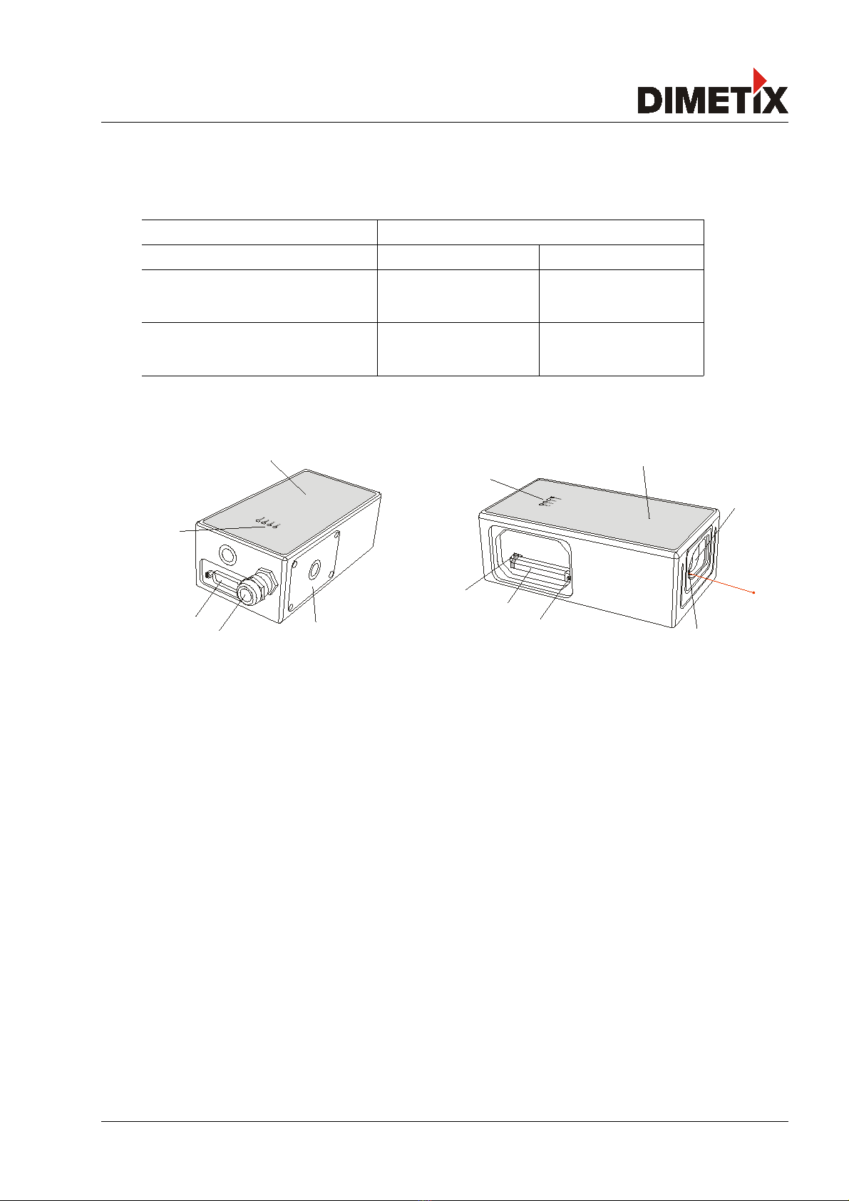
1.2 omponents
1 Status LEDs
status signaling
2 15-Pin D-Sub connector
RS422, RS232, analog, digital output
3 able gland (M16 x 1.5mm)
for connection cable insertion
4 over
provides access to electrical components
5 Reset switch
resets the DLS-B(H) to default settings
6 Screw terminal
RS422, RS232, analog, digital output
7 ID switch
defines the module ID for RS422 operation
8 Laser beam outlet
9 Receiver optics
10 Product label
see 10.9 Labeling on page 42
1.3 Validity
This manual is valid for DLS-B(H) devices with the following software version:
Interface software version: 0100 or later
odule software version: 0100 or later
To get the software version for the DLS-B(H) use the command described in8.3.9 Get Software Version (sNsv) on
page 28
Distance Laser Sensor V1.02 Page 4/43
7
6
5
9
1
8
10
1
2
1
10
4
3

TE HNI AL REFEREN E MANUAL
1.4 Measurement range
The DLS-B(H) is an optical instrument, whose operation is influenced by environmental conditions. Therefore,
the measurement range achieved in use may vary. The following conditions may influence the measurement
range:
Key Factors increasing range Factors reducing range
Target surface Bright and reflective surfaces such as the
target plates (See 9 Accessories on page 35)
att and dark surfaces
Green and blue surfaces
Airborne particles Clean air Dust, fog, heavy rainfall, heavy snowfall
Sunshine Darkness Bright sunshine on the target
The DLS-B(H) does not compensate for the influence of the atmospheric environment, which may be relevant
when measuring long distances (e.g. > 150m). These effects are described in:
B.Edlen: “The Refractive Index of ir, Metrologia 2”, 71-80 (1966)
1.5 Prevention of erroneous measurements
1.5.1 Rough surfaces
On a rough surface (e.g. coarse plaster), measure against the center of the illuminated area. To avoid measuring
to the bottom of gaps in the surface use a target plate (see accessories) or board.
1.5.2 Transparent surfaces
To avoid measuring errors, do not measure against transparent surfaces such as colorless liquids (such as water)
or (dust-free) glass. In case of unfamiliar materials and liquids, always carry out a trial measurement.
Erroneous measurements can occur when aiming through panes of glass,
or if there are several objects in the line of sight.
1.5.3 Wet, smooth, or high-gloss surfaces
1 Aiming at an “acute“ angle deflects the laser beam. The DLS-B(H) may receive a signal that is
too weak (error message 255) or it may measure the distance targeted by the deflected laser beam.
2 If aiming at a right angle, the DLS-B(H) may receive a signal that is too strong (error message 256).
1.5.4 Inclined, round surfaces
easurement is possible as long as there is enough target surface area for the laser spot.
1.5.5 Multiple reflections
Erroneous measurements may occur if the laser beam is reflected by other objects than the target. Avoid any
reflective object along the measurement path.
Distance Laser Sensor V1.02 Page 5/43

TE HNI AL REFEREN E MANUAL
2 Device setup
We recommend that you carry out the configuration steps in an office before mounting the device, especially if
you are not familiar with the DLS-B(H).
The DLS-B(H) supports two types of operating modes:
•Controlled mode
•Automatic mode (for use in stand-alone operation)
The first decision to be taken is the type of operating mode that will be used to transmit the distance
measurement data. While the controlled mode provides maximum flexibility and accuracy, it is often not suitable
for integration into existing PLCs or analog environments. In such cases the automatic mode might be preferred.
Key controlled mode automatic mode
(with analog and/or digital outputs
Accuracy aximum measurement accuracy Accuracy depends on signal scaling
(see 8.3.5 Set/Get distance range (sNv) on page
26)
Flexibility Access to full command set Limited
Integration Requires protocol implementation Wiring of AO and/or DO signals
Connection Connection of up to 10 DLS-B(H)s to a
single RS-422 line.
Point-to-point connection
The following two sections describe the configuration of the DLS-B(H) for the controlled and automatic modes.
2.1 onnection
To be able to configure the DLS-B(H), it must be powered and connected to a PC. Figure 2 shows the necessary
connections. On the PC, any terminal program can be used to communicate with the module. A configuration
utility is also available on the web page www.dimetix.com.
Distance Laser Sensor V1.02 Page 6/43
Fig. 2 Connection for DLS-B(H) configuration
DLS-B(H)
9 pin
D-Sub
Tx
Gnd
2
5
3
Tx
Rx
2
1
GND
V+
Rx
15 pin
D-Sub
9..30VDC
24..30VDC for Heating option
+-
14,15
7,8
Default setting:
Baud:
Bit:
Parity:
Stop:
19200
7
even
1
CO 1 or CO 2

TE HNI AL REFEREN E MANUAL
2.2 ontrolled mode
In controlled mode, each operation of a DLS-B(H) is triggered by a command sent from a host system over a
serial line. While a single device can be connected to the host system using the RS232 interface, up to 10
devices can be connected to a single serial RS422 line. The related command set is described in Chapter 8 on
page 20.
2.2.1 onfiguration
After connecting the module, the steps below are necessary to configure the DLS-B(H) for the controlled
interface mode.
No. Action Comment Command
1 Set ID switch Changes to the module ID are activated
after a power cycle.
Example for module 0:
Change the ID Switch to position 0
Set ID switch to position 0
Power OFF; Wait 10s; Power ON
2
Set controlled mode Set the DLS-B(H) to the controlled
mode, if not already in controlled
mode.
Example for module 0:
Set to controlled mode by means of the
stop command.
s0c<trm>1)
3
Set communication
parameters
If necessary, change the settings for the
serial interface.
Example for module 0:
Set serial interface to 19200 Baud, 8
Bit, no Parity
s0br+2<trm>1)
Power OFF; Wait 10s; Change settings
on the host; Power ON
1) Commands are described in 8 Command set on page 20
Note: If the communication parameters of the module are lost, please reset the configuration to the
factory settings (7 Factory settings on page 19) using the reset button (5.2 Reset switch on page
16). Please note that the ID switch must be reset manually.
2.2.2 Host software
Host software is required for operation of the DLS-B(H) in controlled mode. When connecting multiple devices
to a single serial line (RS422), strict aster-Slave communication must be implemented (DLS-B(H) operates as
slave). For software sample-code or application-notes please consult our web site www.dimetix.com.
Careful testing of the host software together with the devices prior to installation is strongly recommended.
Distance Laser Sensor V1.02 Page 7/43

TE HNI AL REFEREN E MANUAL
2.3 Automatic mode
A automatic mode is provided for host-less operation of the DLS-B(H). The analog and digitals outputs are
updated according the configuration described below as soon as the unit is powered up.
nalog Output
The analog output is configurable and works with two ranges:
–0..20mA
–4..20mA
Digital Outputs
Three digital outputs are included in the DLS-B(H). Two are programmable, while the third is used to
signal an error state of the device.
2.3.1 onfiguration
After connecting the module, the following steps are necessary to configure the DLS-B(H) for automatic mode.
No. Action Comment Command
1
Set current output
range
Defines the current output range
from 0 to 20mA or from 4 to 20mA.
Example for module 0:
Set current output range from 4mA
to 20mA.
s0vm+1<trm>1)
2
Set distance range Defines minimum distance (Dmin)
and the maximum distance (Dmax)
for the distance range of the analog
output.
Example for module 0:
Set distance range from 0m to 10m
s0v+00000000+00100000<trm>1)
3
Set analog output in
case of an error
Sets the current that should be
applied in case of an error.
Example for module 0:
Set current to 0mA in case of an
error.
s0ve+000<trm>1)
4
Configure digital
output
Set the ON and OFF level for the
digital outputs.
Example for module 0:
DO 1: off=2000mm on=2005mm
DO 2: off=4000mm on=4005mm
s01+00020000+00020050<trm>1)
s02+00040000+00040050<trm>1)
5
Save settings The changed configuration must be
saved to make it permanent.
Example for module 0:
Save settings for module 0
s0s<trm>1)
Distance Laser Sensor V1.02 Page 8/43

TE HNI AL REFEREN E MANUAL
No. Action Comment Command
6
Set automatic mode Set the DLS-B(H) to the automatic
mode with the desired update rate.
Example for module 0:
Set measurement rate to fastest
possible speed.
s0A+0<trm>1)
1) Commands are described in 8 Command set on page 20
Node: If the serial line settings of the module have been lost, please reset the configuration to the factory
settings (7 Factory settings on page 19) using the reset button (5.2 Reset switch on page 16). Please
note that the ID switch must be reset manually.
2.4 Display Mode
If Display ode is enabled, the DLS-B(H) formats the measured distance as ASCII string, which is understood by
External Displays with a serial interface. Since the DLS-B(H) outputs this formatted string automatically on the
serial interface after completing a measurement. easurement results can be displayed on an external display
without an additional controller.
For a detailed description of this mode, please contact Dimetix or your dealer.
Distance Laser Sensor V1.02 Page 9/43
2
1
Rx
Tx
m
GND
14,15
RS232 or RS422
TE HNI AL REFEREN E MANUAL
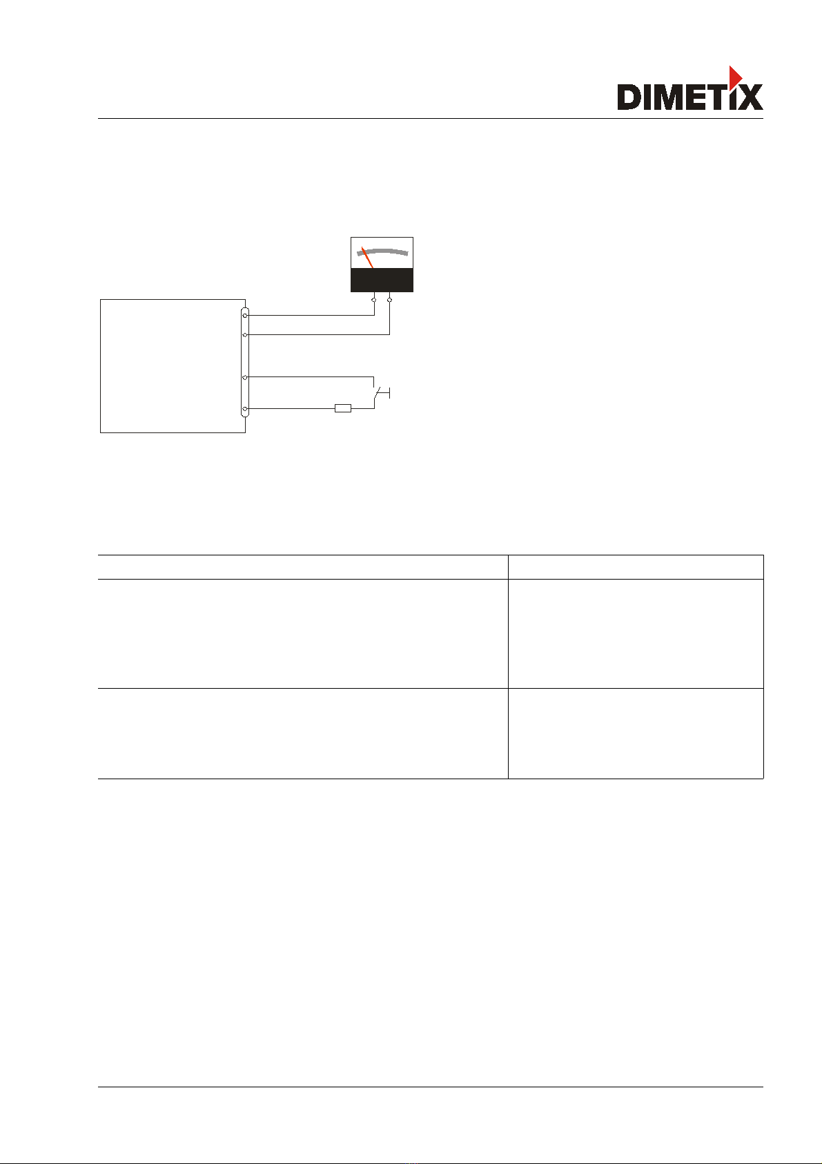
2.5 External Trigger
The DLS-B(H) includes the option of triggering measurements with an external switch or push button on Digital
Input 1 (DI 1). Using the Digital Input DI 1 disables the Digital Output DO 1.
The command to activate the external trigger option is described in 8.4 Digital Input on page 30.
2.5.1 onfiguration
After connecting the DLS-B(H), the following steps are necessary to activate the external trigger. The example
shows the configuration for triggering a single distance measurement.
No. Action Comment Command
1
Activate digital input
DI1
Defines the action for a trigger
event on DI1.
Example for module 0:
Configure DI1 to trigger a single
distance measurement.
s0DI1+2<trm>1)
5
Save settings The changed configuration must be
saved to make it permanent.
Example for module 0:
Save settings for module 0
s0s<trm>1)
1) Commands are described in 8 Command set on page 20
Distance Laser Sensor V1.02 Page 10/43
12
13
AO
AGND
DO/DI 1
V+
7,8
9
1k
DLS-B(H)
TE HNI AL REFEREN E MANUAL
3 Installation
3.1 Mounting
Three 4 threaded holes in the bottom of the DLS-B(H) make it easy to mount the device.
Always obey all applicable safety regulations and never use the device outside the specifications stated under
4 Technical data on page 14
3.2 Device wiring
3.2.1 Power Supply
For trouble-free operation use a separate power supply for the DLS-B(H).
DLS-B: 9...30V, 0.5A DC
DLS-BH: 24...30V, 2.5A DC
3.2.2 able connection
A ferrite core must be fitted to the connecting cable. Use a ferrite core with an impedance of 150 Ω to 260 Ω
at 25 Hz and 640 Ω to 730 Ωat 100 Hz. For example you can use KCF-65 from KE Kitagawa.
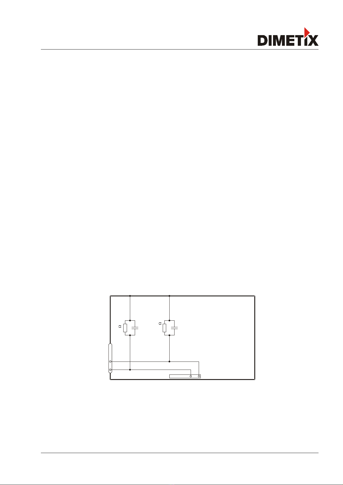
3.2.3 Shield and Ground
The DLS-B(H) contains two electrically isolated grounds, the general ground (GND) and the analog ground
(AGND). GND and AGND are connected to the housing by a RC element. Please see figure 5
Distance Laser Sensor V1.02 Page 11/43
DLS-B(H)
Screw terminal
GND
AGND
15 pin D-Sub
GND
AGND
20nF
1
10nF
500k

TE HNI AL REFEREN E MANUAL
3.2.4 ontrolled mode
RS232
Only point-to-point communication is possible when using the RS232 interface.
❢Never connect multiple DLS-B(H)s on a RS232 serial line
RS422
It is possible to connect multiple devices on a single RS422 line. To ensure proper operation, strict aster-Slave
communication must be applied. It is important, that the aster has full control of the communication and
never initiates a new communication before termination of the previous communication (answer from the DLS-
B(H) or timeout).
❢Ensure, that all DLS-B(H)s are set to different ID numbers
Distance Laser Sensor V1.02 Page 12/43
Tx
Host
(PC or PLC)
Rx
TxRx
2
7,8
1
14,15
V+
9..30VDC
24..30VDC with Heating
0V
R+
R-
T+
T-
ID switch
Position 0
A
B
A
B
Host
(PC or PLC)
R
t
R
t
5
4
6
3
14,15
R
t
R
t
7,8
V+
R+
R-
T+
T-
ID switch
Position 1
5
4
6
3
14,15
7,8
V+
R+
R-
T+
T-
ID switch
Position 9
5
4
6
3
14,15
7,8
V+
9..30VDC
24..30VDC with Heating
0V
(slave) (slave) (slave)
(master)
DLS-B(H)
DLS-B(H) DLS-B(H) DLS-B(H)

TE HNI AL REFEREN E MANUAL
3.2.5 Automatic mode
The analog interface of the DLS-B(H) is isolated from the rest of the device. When using the analog interface,
connect the analog ground (AGND).
ake sure, that the total resistance in the analog path is lower than 500 Ω.
3.3 Alignment of the laser beam
Alignment of the laser beam is often difficult when the target is far away, as the laser spot is not visible. An
optional telescopic viewfinder is available which simplifies alignment significantly. Please refer to chapter 9
ccessories on page 35 for a description of the viewfinder.
Distance Laser Sensor V1.02 Page 13/43
DLS-B(H)
Analog Input
0..20mA
12
14,15
13
Digital Input
24V=
9..30VDC
24..30VDC for Heating Option
0V
PLC
AO
AGND
DO 1
DO 2
V+
GND
7,8
9
10
TE HNI AL REFEREN E MANUAL
4 Technical data
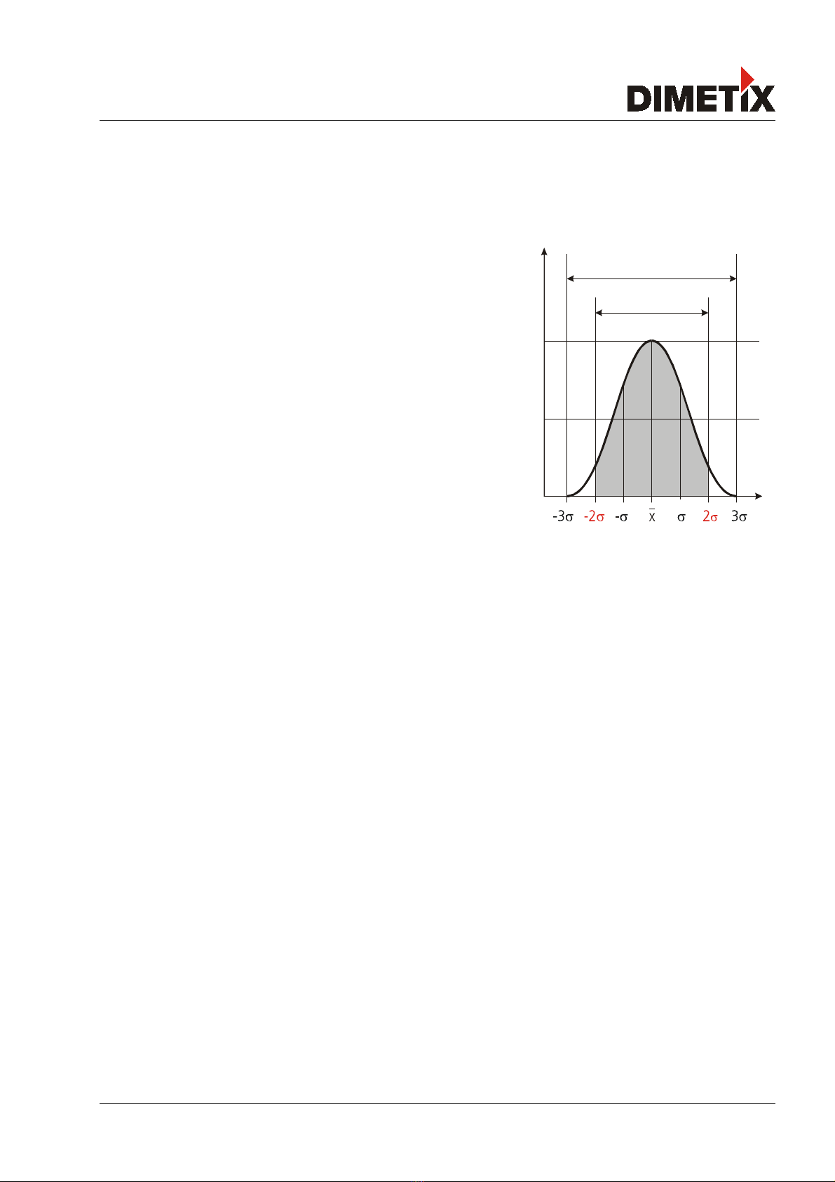
4.1 Measuring accuracy
The measuring accuracy corresponds to the ISO-recommendation ISO/R
1938-1971 with a statistical confidence level of 95.4% (i.e. ± twice the
standard deviation σ, refer to diagram on the right). The typical
measuring accuracy relates to average conditions for measuring. It is
±1.5mm for the DLS-B(H) 15 and ± 3.0mm for the DLS-B(H) 30 valid in
the tracking mode
The maximum measuring error relates to unfavorable conditions such
as:
- Highly reflective surfaces (e.g. reflector tapes)
- Operation at the limits of the permitted temperature range,
adaptation to ambient temperature canceled
- Very bright ambient conditions, strong heat shimmer
and can be up to ± 2 mm for DLS-B(H) 15 and ± 5 mm for DLS-B(H) 30. The DLS-B(H) does not compensate
changes of atmospheric environment. These changes can influence the accuracy if measuring long distances
(>150m) under conditions very different from 20°C, 60% relative humidity and 953 mbar air pressure. The
influences of the atmospheric environment are described in
B.Edlen: “The Refractive Index of ir, Metrologia 2”, 71-80 (1966)
Distance Laser Sensor V1.02 Page 14/43
99.7%
95.4%
TE HNI AL REFEREN E MANUAL
4.2 Specifications
Typical measuring accuracy for
DLS-B 15 / DLS-BH 15 1)
DLS-B 30 / DLS-BH 30 1)
± 1.5 mm @ 2σ
± 3.0 mm @ 2σ
Smallest unit displayed 0.1 mm
easuring range on natural surfaces 0.05 to approx. 65 m
easuring range on orange (reflective) target plate.
See chapter 9.2 Target plates on page 35.
0.05 to 500 m
easuring reference from front edge (See 6 Physical dimensions)
Diameter of laser spot at target at a distance of 4mm @ 5 m
8mm @ 10m
approx. 28mm*14mm @ 50m
approx. 40mm*25mm @ 100 m
Time for a measurement
Single measurement
Tracking
0.15 to approx. 4 sec
0.15 to approx. 4 sec
Light source Laser diode 620-690 nm (red)
IEC 60825-1:2001; Class 2
FDA 21CFR 1040.10 and 1040.11
Beam divergence:0.16 x 0.6 mrad
Pulse duration: 0.45x10⁻⁹ s
aximum radiant power: 0.95 mW
Laser Life Time > 50'000h @ 20°C
ESD IEC 61000-4-2 : 1995 +A1 +A2
E C EN 61000-6-4
EN 61000-6-2
Power supply 9 ... 30V DC 0.5A for DLS-B
24 ... 30V DC 2.5A for DLS-BH (Heating option)
Dimensions 150 x 80 x 55 mm
Temperature range during operation 2)
DLS-B 15 / DLS-B 30
DLS-BH 15 / DLS-BH 30
-10 °C to +50 °C
-40 °C to +50 °C
Temperature range during storage -40 °C to +70 °C
Degree of Protection IP65; IEC60529 (protected against ingress of dust and
water)
Weight DLS-B(H): 665 g
DLS-B(H): 690 g
Interface 1 serial asynchronous interface (RS232/RS422)
1 programmable analog output 0/4 .. 20mA
2 programmable digital outputs
1 programmable digital input
1 digital output for error status
1) See 4.1 easuring accuracy on page 14.
2) In case of permanent continuous measurement (tracking mode) the max. temperature is reduced to 45°C
Distance Laser Sensor V1.02 Page 15/43

TE HNI AL REFEREN E MANUAL
5 Electrical components
5.1 ID switch
This switch is used to set the module ID and can be set from 0 to 9. Default setting is 0.
5.2 Reset switch
To reset the module to factory settings do the following:
•Switch OFF the power for the module
•Press the reset button and keep it pressed
•Switch on the power for the module
•Keep the reset button pressed until all LEDs on the module are illuminated
•Release the reset button.
•Switch the power OFF and wait 5 seconds.
•Switch on the power and wait until the green power LED is on.
5.3 Digital output
The DLS-B(H) contains two digital outputs for level monitoring (DO 1 and DO 2)
and one digital output for error signalization (DO E). These outputs are open drain
outputs as shown in figure 7 and can drive up to 200mA. aximum switching
voltage is 30V DC. In the ON state, the FET transistor is electro conductive.
5.4 Digital Input
The Digital Output (DO 1) can be configured as a Digital Input (DI 1). This is useful for triggering measurements
by means of an external switch or push button. Please refer to chapter 8.4 Digital Input on page 30.
Low Level is: U DI1 < 2VDC
High Level is: U DI1 > 9VDC and U DI1 < 30VDC
5.5 Analog output
The analog output of the DLS-B(H) is a current source (0..20mA or 4..20mA). It is capable of driving loads up to
500Ω. The analog output has an accuracy of +/- 1% Full scale.
e.g. The configured measurement range is 0...20m and the actual measured distance is 14m. This results in a
measurement uncertainty of ± 0.2m (1% of 20m), which includes all parameters (temperature drift,
sensor accuracy, linearity, target color etc.). The uncertainty decreases, if the ambient temperature is
stable.
Distance Laser Sensor V1.02 Page 16/43
Fig. 7 Open drain output
uMax=max. uncertainty
Conf MaxDist =DDistance programmed for the maximum output current
Conf MinDist =DDistance programmed for the minimum output current
uMax=Range
100 =Conf MaxDist−Conf MinDist
100
DOUT
On
TE HNI AL REFEREN E MANUAL
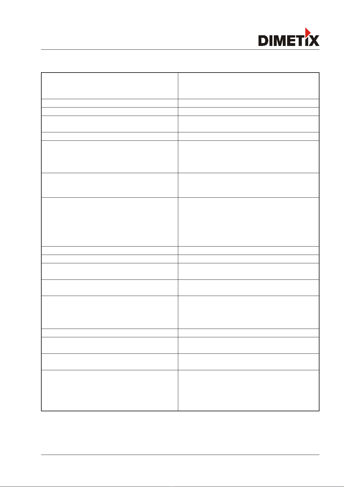
5.6 onnector
5.6.1 D-Sub connector
Pin Designator Description
1 Rx RS232 receive line
2 Tx RS232 send line
3 T- RS422 send line negative
4 T+ RS422 send line positive
5 R- RS422 receive line negative
6 R+ RS422 receive line positive
7 PWR
8 PWR
DC Power
+ 9V…+30V for DLS-B
+24V…+30V for DLS-BH (Heating option)
9 DO 1 Digital output 1 (Open Drain) or Digital input 1
10 DO 2 Digital output 2 (Open Drain)
11 DO E Digital output for error signalization (Open Drain)
12 AGND Analog ground
13 AO Analog output (0/4..20mA)
14 GND Ground line
15 GND Ground line
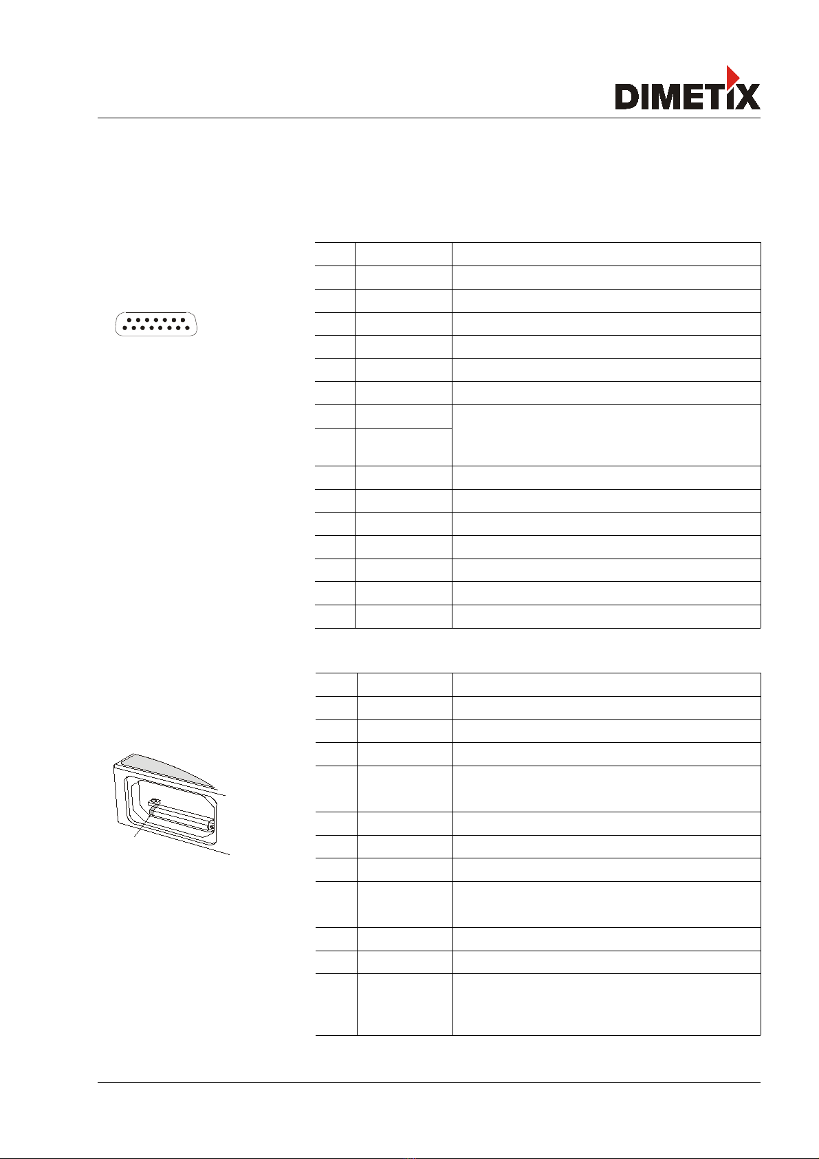
5.6.2 Screw terminal
Pin Designator Description
1 R+ RS422 Receive line positive
2 R- RS422 Receive line negative
3 T+ RS422 Send line positive
4 T- RS422 Send line negative
5 Tx RS232 Transmit line
6 Rx RS232 Receive line
7 AGND Analog ground
8 AO Analog output (0/4..20mA)
9 DO E Digital output for error signalization (Open Drain)
10 DO 2 Digital output 2 (Open Drain)
11 DO 1 Digital output 1 (Open Drain) or Digital input 1
12 GND Ground line
13 PWR Power DC
+9V...+30V DLS-B
+24...+30V DLS-BH (Heating option)
Distance Laser Sensor V1.02 Page 17/43
No.1
1
9
15
8

TE HNI AL REFEREN E MANUAL
6 Physical dimensions
All dimension in mm
Distance Laser Sensor V1.02 Page 18/43
150.0
38.5
88.5
easuring reference
= =
3 x 4 x 5
54.0
80.0
16 x 1.5
40.0
= =
152.5
80.0
Laser Beam
32.2
28.5
36.0
14.5

TE HNI AL REFEREN E MANUAL
7 Factory settings
7.1 Operation
ode: Controlled ode
7.2 ommunication parameters
Baud: 19200
Data bit: 7
Parity: Even
Stop bit: 1
7.3 Analog outputs
in output: 4mA
Range min: 0m
Range max: 10m
Error output: 0mA
7.4 Module ID
ID Number: 0
7.5 Digital output 1 (DOUT1)
ON: 2m + 5mm = 2005mm
OFF: 2m - 5mm = 1995mm
7.6 Digital output 2 (DOUT2)
ON: 1m – 5mm = 995mm
OFF: 1m + 5mm = 1005mm
7.7 Digital input 1 (DI1)
Inactive, configured as output
7.8 User distance offset
User distance offset = 0mm
Distance Laser Sensor V1.02 Page 19/43

TE HNI AL REFEREN E MANUAL
8 ommand set
8.1 General
8.1.1 ommand termination <trm>
All commands for the DLS-B(H) are ASCII based and terminated <trm> with <cr><lf>.
8.1.2 Module identification N
Since the module can be addressed with the ID switch, the ID is represented in the commands by N. At the
location of the N insert the odule ID.
8.1.3 Parameter separator
The command syntax uses the '+' sign as parameter separator. The '+' sign can be replaced by the minus '-'
sign if applicable by the command.
8.1.4 Set/Get ommands
All configuration commands that are used to set configuration values can also be used to read the currently set
value by omitting the parameter. The command syntax is described as follows:
Set ommand Get ommand
Command sNuof+xxxxxxxx<trm> sNuof<trm>
Return successful gNof?<trm> gNuof+xxxxxxxx<trm>
Return Error gN@Ezzz gN@Ezzz
Parameters Nodule ID
xxxxxxxx Offset in 1/10 mm; + positive / - negative
zzz Error code
8.1.5 Startup sequence
After power on the DLS-B(H) does all the initializations and sends a start sequence gN?. On this sequence, the
N stands for the odule ID. After sending this start sequence, the DLS-B(H) is ready to use.
Distance Laser Sensor V1.02 Page 20/43
This manual suits for next models
3
Table of contents
Other Dimetix Measuring Instrument manuals


Popular Measuring Instrument manuals by other brands


Levitronix
Levitronix LEVIFLOW LFSC-D Series user manual

Teledyne
Teledyne HASTINGS 2002 instruction manual

Michelin
Michelin 12290 Operation instructions

Anritsu
Anritsu MS9740B Operation manual

ADS
ADS Intrinsically-Safe TRITON+ Installation, operation and maintenance manual

Cocraft
Cocraft HD400 Original instructions


