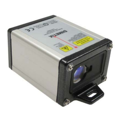
Dimetix FLS-C Installation and operating instructions

Application Note
AN2019
Moving Target Characteristic with SSI
FLS-C
Abstract
The “Moving target characteristic” is made for fast position measuring on continuous moving targets. This
document describes the necessary settings of the FLS-C sensor for the "Moving target characteristic" as well as
the configuration of the SSI and Analog interface.
V1.00
Please check www.dimetix.com
for the latest version
This application note is provided as is without any warranty for any problems this sample may cause.
Dimetix AG, Degersheimerstrasse 14, CH-9100 Herisau, Switzerland
Phone: +41 71 353 0000, Fax: +41 71 353 0001, E-mail: info@dimetix.com
©
Copyright by Dimetix AG
www.dimetix.com
Laser Distance Sensors

Table of Contents
1 Introduction...................................................................................................................................................................................................3
1.1 Feedback positioning...........................................................................................................................................................................3
1.2 Usable sensors.....................................................................................................................................................................................3
2 Preparation....................................................................................................................................................................................................4
2.1 Connect DLS/FLS UtilitySW with the FLS-C...........................................................................................................................................5
3 Measurement characteristic configuration.....................................................................................................................................................6
4 Interface setup..............................................................................................................................................................................................7
4.1 General................................................................................................................................................................................................7
4.2 SSI........................................................................................................................................................................................................7
4.2.1 Configuration of the SSI output..................................................................................................................................................7
4.2.2 Wiring........................................................................................................................................................................................8
4.3 Analog / Digital....................................................................................................................................................................................9
4.3.1 Configuration of the analog output............................................................................................................................................9
4.3.2 Configuration of the digital output...........................................................................................................................................10
4.3.3 Wiring......................................................................................................................................................................................10
5 Measurement mode....................................................................................................................................................................................11
5.1 Auto start..........................................................................................................................................................................................11
5.2 Manual start......................................................................................................................................................................................12
5.2.1 Digital input connection...........................................................................................................................................................12
Moving Target Characteristic with SSI AN2019 Page 2 of 12
Laser Distance Sensors

1Introduction
Different measurement characteristics are implemented into the FLS-C. This measurement characteristics provide
the necessary flexibility to configure the FLS-C for various applications.
The FLS-C laser distance sensor is able to measure continuous moving targets with a speed of 200Hz, as long as
there are no distance jumps. While the FLS-C is measuring with 200Hz the “SSI” interface is the best choice to
transfer the measured results to the host system. This digital interface is fast and has no additional noise.
In addition the analog output is updated with 200Hz also.
The disadvantage of the analog interface is the accuracy, that depends on the configured distance range. In
addition noise will be added to the analog signal.
This document describes the configuration and connection of the FLS-C for the use with the “Moving target
characteristic” with SSI. While this document provides step by step configuration instructions, the Technical
Reference Manual gives a more detailed description.
1.1 Feedback positioning
Fig. 1 shows a typical positioning application, that uses “Moving target characteristic”. In this application, the
FLS-C laser distance sensor measures absolute distances, that can be used as real time feedback for the position
controller implemented in the drive.
Ensure that no distance jumps occur in order to use the “Moving target characteristic”.
1.2 Usable sensors
The following sensors can be used for such kind of applications.
Sensor Part No Short description
FLS-C 10 600502 Distance sensor with an accuracy of +/-1mm, max Distance 500m, Temperature range -10..+50°C
FLS-C 30 600501 Distance sensor with an accuracy of +/-3mm, max Distance 500m, Temperature range -10..+50°C
FLS-CH 10 600504 Distance sensor with an accuracy of +/-1mm, max Distance 500m, Temperature range -40..+50°C
FLS-CH 30 600503 Distance sensor with an accuracy of +/-3mm, max Distance 500m, Temperature range -40..+50°C
Moving Target Characteristic with SSI AN2019 Page 3 of 12
Laser Distance Sensors
Fig. 1: Positioning application with feedback controller
Position
SSI
Field
bus
PLC Drive
Encoder

2 Preparation
1. The following items are needed to do the configuration of the FLS-C.
•RS-232 Configuration cable FLS / DLS (Part no. 500200)
•24V DC Power supply
2. Download the DLS/FLS UtilitySW from the website http://www.dimetix.com/UtilitySW/ and install it on a PC.
3. Connect the FLS-C sensor to the PC and to the 24V DC Power supply as shown in Fig 2.
4. Start the DLS/FLS UtilitySW on the PC.
Moving Target Characteristic with SSI AN2019 Page 4 of 12
Laser Distance Sensors
Fig. 2: Configuration connection
9 pin
D-Sub
Tx
Gnd
2
5
3
Tx
Rx
2
1
GND
V+
Rx
15 pin
D-Sub
9..30VDC
24..30VDC for Heating option
+
-
14,15
7,8
Defaultsetting:
Baud:
Bit:
Parity:
Stop:
19200
7
even
1
COM1 or COM2

2.1 Connect DLS/FLS UtilitySW with the FLS-C
After start-up of the DLS/FLS UtilitySW the window shown in Fig. 3 is visible. Set the “Communication
parameters” corresponding to the connection of the FLS-C sensor and press the “CHECK CONNECTION”
button.
Fig. 3: Start window of the DLS/FLS UtilitySW
After the DLS/FLS UtilitySW connected successfully to the FLS-C sensor, the “Software version and serial
number” section is updated as shown in Fig. 4. Further the “Status:” field at the bottom will show “OK”. If the
DLS/FLS UtilitySW does not show the described information, the connection with the FLS-C is not done properly.
If the connection is not done properly, press the reset button and follow the description to reset the sensor. Then
make sure that the Port setting is correct and press the “CHECK CONNECTION” Button again.
Fig. 4: Start window after "CHECK CONNECTION" procedure
Moving Target Characteristic with SSI AN2019 Page 5 of 12
Laser Distance Sensors

3 Measurement characteristic configuration
Activate the “Moving target characteristic” to be able to measure with 200Hz. To do so, change to the
“Configuration” tab and select the “Measurement characteristic” sub tab on the left, check “Moving target”
and press the “DOWNLOAD TO DEVICE” button. Fig. 5 shows the mentioned settings.
Moving Target Characteristic with SSI AN2019 Page 6 of 12
Laser Distance Sensors
Fig. 5: Configuration of the “Moving target characteristic”

4 Interface setup
4.1 General
While the FLS-C measures with “Moving target characteristic” the measured distances are available on all
interfaces. The following examples show the use of different interfaces.
4.2 SSI
The FLS-C device contains a SSI interface, that operates as SSI slave. This interface shares the connection pins
with the integrated RS422 interface. Hence the RS422 and the SSI interface can not be used at the same time.
While the FLS-C device is a SSI-slave the host has to be the SSI-master, which generates the clock.
Never connect the FLS-C to a SSI master before the interface is configured as SSI.
Always configure the interface before connecting to the master.
4.2.1 Configuration of the SSI output
On the “Configuration” tab, select the “SSI” sub tab on the left. In the “4-pole serial port usage sNSSI” area
select SSI to deactivate the RS-422 interface and activate the SSI interface and set the SSI configuration
corresponding to the configuration of the SSI master.
Further define the output value in case of an error as shown in Fig. 6. After configuring all options press the
“DOWNLOAD TO DEVICE” button to save the settings in the FLS-C.
Data format
The following figure shows the format of the output with the maximum length. Error code and Error bit can be
switched of and the data can be reduced to 23 bit. The data can be either binary or gray coded.
Data (24 Bit binary/gray)
Error code (binar
y/g
ray)
Error bit
MSB ff LSB MSB LSB
23222120191817161514131211109876543210765432100
Error behavior
In case of an error the data field contains a replacement value, the last valid distance or the error code,
depending on the configuration.
Moving Target Characteristic with SSI AN2019 Page 7 of 12
Laser Distance Sensors
Fig. 6: SSI interface configuration
SSI configuration

4.2.2 Wiring
Never connect the FLS-C to a SSI master before the interface is configured as SSI.
Always configure the interface before connecting to the master.
Connect the SSI interface to the SSI master as shown in Fig. 7. As soon as the master activates the clock, the FLS-
C returns the SSI data. For more detailed information about the SSI interface see the Technical Reference Manual
and AN2002 FLS-C SSI Interface.
Moving Target Characteristic with SSI AN2019 Page 8 of 12
Laser Distance Sensors
Fig. 7: SSI interface connection
Clock+
SSI clock
SSI data
R+
R-
T+
T-
5
4
6
3
7,8
V+
(SSI Clock in +)
(SSI Clock in -)
(SSI data out +)
(SSI data out -)
14,15
0V
Vcc
twisted pair
connection
GND
SSI master
(i.e. controller)
SSI slave
FLS-C(H)
Clock-
Data+
Data-
Terminal

4.3 Analog / Digital
The analog and digital outputs are updated after each measurement executed by the FLS-C. The scaling of the
analog output and the switching limits of the digital outputs can be configured with the DLS/FLS UtilitySW.
4.3.1 Configuration of the analog output
In the DLS/FLS UtilitySW select the “Configuration” tab and open the “Analog output” sub tab on the left. Fig. 8
shows the configuration of the analog output for the following settings.
Distance Current Situation Current
10m 20mA Error 2mA
0m 4mA Cable break 0mA
After setting the values as shown in Fig 8 press the “DOWNLOAD TO DEVICE” button to save the configuration
in the FLS-C.
Moving Target Characteristic with SSI AN2019 Page 9 of 12
Laser Distance Sensors
Fig. 8: Analog output configuration

4.3.2 Configuration of the digital output
Fig. 9 shows a possible configuration of the digital outputs. In this example, the digital output 2 will switch off, if
the distance is over 1005mm and switch on if below 995mm, hence the hysteresis is 10mm.
On the “Configuration” tab, select the “Digital output” sub tab on the left and set the values as shown in Fig. 9.
After configuring all options press the “DOWNLOAD TO DEVICE” button to save the settings in the FLS-C.
If you use manual start (see 5.2 Manual start), digital output 1 can not be used, since this pin will be used as
digital input to trigger the measurement.
4.3.3 Wiring
Fig 10 shows how to connect the analog and digital output.
If you use “Manual start” configuration (see 5.2 Manual start) do not use DO1 as output.
Moving Target Characteristic with SSI AN2019 Page 10 of 12
Laser Distance Sensors
Fig. 10: Analog and digital output connection
Fig. 9: Digital output configuration
12
14,15
13
24V=
9..30VDC
24..30VDC for Heating Option
0V
AO
AGND
DO 2
V+
GND
7,8
10
FLS-C

5 Measurement mode
After the configuring the “Measurement characteristic” and the interfaces, the start for the measurement must
be set up. The table below outlines the two different possibilities.
Auto start Manual start
The FLS-C is configured to start measuring after power
on automatically.
The FLS-C is configured to start measuring depending
on the signal on the digital input.
5.1 Auto start
Use this configuration if the sensor should start measuring automatically after every power on.
In the “Stand-alone Mode” tab, select “Auto start configuration” sub tab on the left. As shown in Fig. 11, check
the “ON” box and set the “Sample time” input field to 0 sec for fastest possible measurement.
As soon as you press the “DOWNLOAD TO DEVICE” button, the device starts to measure. Now the FLS-C is
configured to start measuring every time after power on.
Moving Target Characteristic with SSI AN2019 Page 11 of 12
Laser Distance Sensors
Fig. 11: Auto start configuration

5.2 Manual start
In Manual start operation, the measurement is controlled be the digital input of the FLS-C. The function of the
digital input can be configured with the DLS/FLS UtilitySW as shown in Fig. 12.
On the “Stand-alone Mode” tab, select the sub tab “Manual start configuration”, select “Active” in the “Digital
input DI1 sNDI1” area. Additionally select “Start / Stop single sensor tracking”. Then press the “DOWNLOAD TO
DEVICE” button. Now the sensor starts measuring when the digital input goes to high level and stops measuring
if the digital input goes to low level.
5.2.1 Digital input connection
After the digital input is configured and connected as shown in Fig. 13, the measurement of the sensor can be
controlled with an external switch or relays.
Moving Target Characteristic with SSI AN2019 Page 12 of 12
Laser Distance Sensors
Fig. 13: Digital input wiring
Fig. 12: Manual start configuration (Digital input)
DO 1/DI
V+
7,8
9
1kW
FLS-C
Table of contents
Other Dimetix Measuring Instrument manuals
Popular Measuring Instrument manuals by other brands
Chopin
Chopin AlveoPC Maintenance manual
Binding Union
Binding Union METER 44 Technical manual

Keysight
Keysight N7744A user guide
IQ Scientific Instruments
IQ Scientific Instruments miniLab IQ128 Elite operating instructions
Fluidwell
Fluidwell F014-P user manual

Hanna Instruments
Hanna Instruments HI781 user manual
