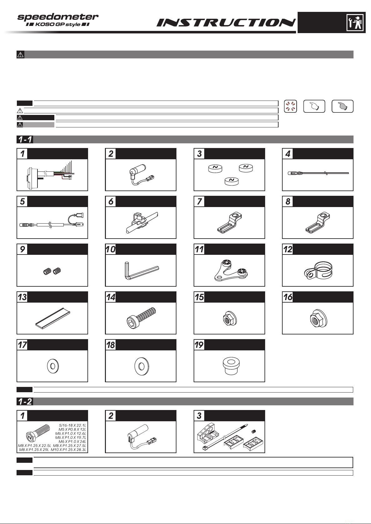
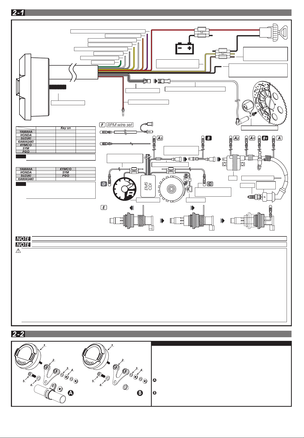
WARNING!
Put the magnet into the
brake disc screw hole.
Higher number of magnets installed on the disk brake will result in a faster speed display on the gauge.
The letter “N” on the magnets must face the speed sensor in order to pick up correctly the speed.
EX 1: If the disk brake has 3 screws, you can install 1 or 3 magnets.
EX 2: If the disk brake has 4 screws, you can install 1,2 or 3 magnets.
EX 3: If the disk brake has 5 screws, you can install 1 or 5 magnets.
EX 4: If the disk brake has 6 screws, you can install 1,2,3 or 6 magnets.
Install the s type sensor
bracket.
Adjust the sensor bracket
position to make sure
the sensor is facing the
magnet to prevent bad
speed signal.
Install the speed sensor
on the bracket.
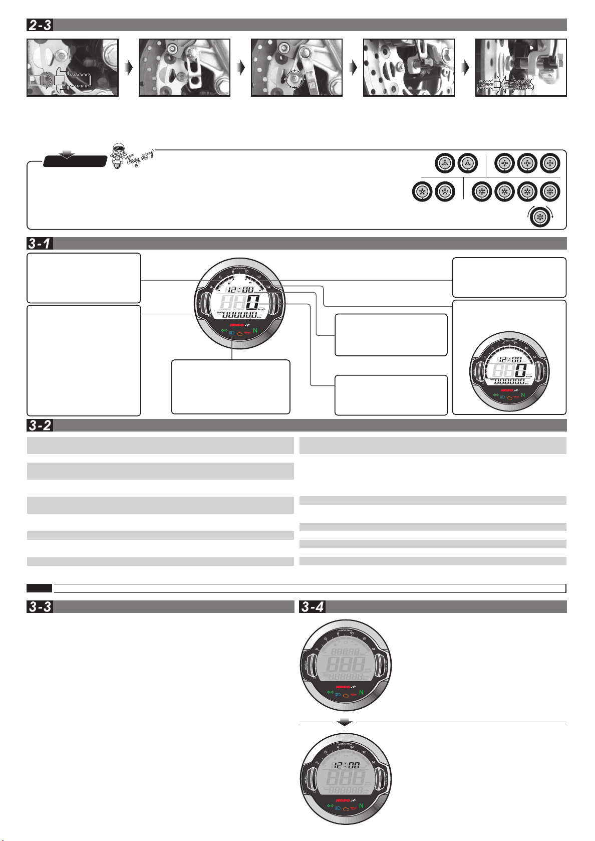
In order to get a good
speed signal, the distance
between the speed sensor
and magnet should be
under 8mm.
Fuel Level
●Display range: 4levels
●The fuel level begins to flash
when only 1 level left.
●If you don’t install the fuel
wiring, the fuel will not display.
Indicators lights
●Turn signal light (Green)
●Neutral light (Green)
●High beam light (Blue)
●Engine oil pressure light (Red)
●EOBD light (Amber)
Setting range: 100Ω、250Ω、510Ω、1200Ω
3-5
wh642bb03b-P4-2
INSTALLATION INSTRUCTION
P.S.
EX. 1 EX.2
EX. 3 EX.4
OVERVIEW
Odometer
●Display range: 0~99999.9
km(mile), reset automatically
after 99999.9 km(mile).
●Display unit: 0.1 km(mile).
Trip meter A. B
●Display range: 0~999.9 km
(mile) , reset automatically
after 999.9 km(mile).
●Display unit: 0.1 km(mile).
Fuel / Remaining Distance
●Display range: 999.9~0 km
(mile).
FUNCTION, SETTING INSTRUCTION
●Speedometer
●Tachometer
Display range: 0~360 km/h (0~225 MPH)
Display unit: 1 km/h (MPH)
○Display interval <0.5 second
○Odometer Display range: 0~99999.9 km (mile), reset automatically
after 99999.9 km (mile) ; Display unit: 0.1 km (mile)
Display range: 999.9~0 km (mile)
Display unit: 0.1 km (mile)
Setting range: 300~2500 mm
Setting unit: 1 mm . Sensor point: 1~20
○Trip meter A. B
○Tire circumference
○Fuel resistance
○Fuel / Remaining
Distance
Display range: 0~999.9 km (mile), reset automatically
after 999.9 km (mile) ; Display unit: 0.1 km (mile)
●Fuel Level Display range: 4 levels
The fuel symbol begins to flash if only 1 level is left.
●Clock 24 H
●Digital Volt meter Display range: DC 5~24 V, Flashing Warning when
Voltage lower than 8V or higher than 18V.
Display range: 4 levels
Dispaly unit: 1 level (Low) - DC 11.6~12.0 V
2 level - DC 12.1~12.5 V
3 level - DC 12.6~13.0 V
4 level (High) - DC 13.1 V~
●Volt meter
○Insufficient volt warning Voltage level begins to flash when only 1 level left
●Backlight brightness adjust Setting range: 1-5(Darkest)~5-5(Brightest)
Setting unit: adding 20 % each adjustment (5 segments)
●Effective voltage
●Effective temperature range -10~+60°C
●Meter standard JIS D 0203 S2
135.7 X 100.7 X 52 mm
●Meter size
Around 240g
●Meter weight
High beam-blue, Turn signal-green
Oil-red, Neutral-green, EOBD light-Amber
●Indicator light color
NOTE Design and specification are subject to change without notice!
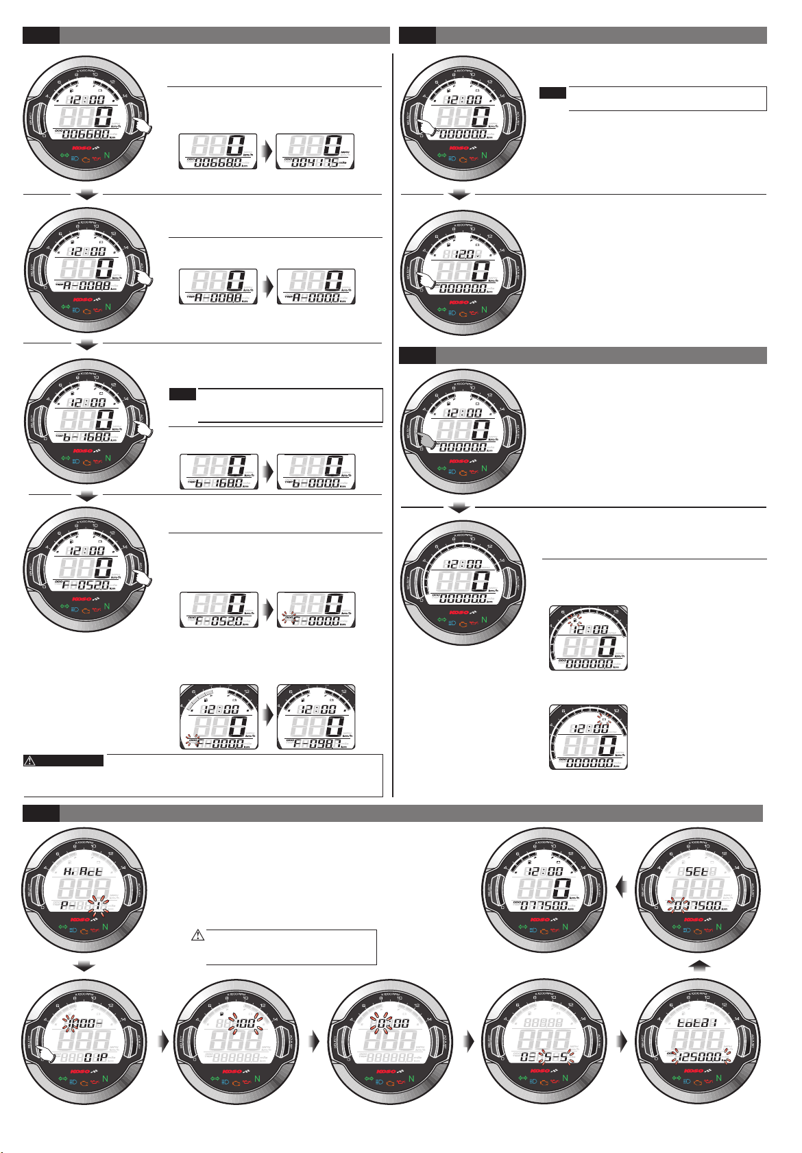
BUTTON FUNCTION INSTRUCTION STAND BY FUNCTION INSTRUCTION
Press the Select button
In main screen: Press the Select button to switch between clock, volt.
In setting screen: Press the Select button to change the setting cursor.
When the meter is off, press the Select button to wake up the clock.
Hold pressing the Select button for 3 seconds.
In main screen: Hold pressing the Select button for 3 seconds to switch between
fuel, volt, RPM.
In setting screen: Hold pressing the Select button for 3 seconds to return the main
screen
Press the Adjust button
In main screen: Press the Adjust button to switch between Odometer, Trip A, Trip B,
Fuel / Remaining distance.
In setting screen: Press the Adjust button to change the setting value.
When the meter is off, press the Adjust button to wake up the clock.
Hold pressing the Adjust button for 3 seconds.
In record screen such as Trip A, Trip B ,hold pressing the Adjust button for 3 seconds
to reset the record, and switching the unit for Mileage and Speed.
Hold pressing the Adjust button for 10 seconds.
In Fuel / Remaining distance screen: Reset the Remaining Mileage to 0 and restart
the learning.
Hold pressing the Adjust button
In setting screen: You could switch the setting value faster by holding pressing the
Adjust button.
Hold pressing the Adjust+Select for 3 seconds
In main screen, Hold pressing the Adjust+Select for 3 seconds to enter the setting screen.
●When the meter is off, press Adjust or Select
button to wake up clock function.
●The clock will display 30 seconds after
wake up.
MAIN FUNCTION SWITCH INSTRUCTION(ADJUST BUTTON)
●In main screen (ODO). Press the Adjust
button one time to enter the Trip A screen.
●In the clock screen, press the Select Button
one time to switch to the volt screen.
●In the volt screen, press the Select Button one
time to switch to the clock screen.
●In the fuel, volt screen, hold pressing the
Select Button for 3 seconds to switch to the
RPM screen.
●In the RPM screen, hold pressing the Select
Button for 3 seconds to switch to the fuel,
volt screen.
In the RPM screen
●When Fuel Level remain 1 level, the Fuel symbol
will flashing as warning.
●In Trip A screen. Press the Adjust button
one time to enter the trip B screen.
●In Trip B screen. Press the Adjust button
one time to enter the Fuel / Remaining
distance screen.
●In the fuel / remaining distance screen, press the
Adjust button one time to go back to the main
screen(ODO).
●Hold pressing Adjust button for 3 seconds
to reset Trip A record.
●Hold pressing Adjust button for 3 seconds
to reset Trip B record.to reset Trip B record.
●Hold pressing the Adjust button for 3
seconds to switch between the digital
speedometer and the digital Odometer.
●In setting screen, you could press the
Select button to enter the setting.
The setting screen is in order as
below:input pulse setting,the tire
circumference setting, the fuel
resistance setting, clock, backlight
brightness, internal odometer display,
external odometer setting.
If you don't take any action in 30
seconds, the screen will return to
the main screen automatically.
Clock
●24 H.
Digital Volt meter
●Display range: DC 5~24 V.
Speedometer
●Display range: 0~360 km/h.
(0~225 MPH)
●Display unit: 1 km/h (MPH)
Volt meter
●Display range: 4 levels.
●The voltage level begins to
flash when only 1 level left.
Tachometer
●Display range: 15 levels.
●Each level represents 1000
RPM.
Display range: 15 levels (Each level represents 1000 RPM)
Remaining Mileage Learning Procedure:
●Fill the tank to full and in the remaining mileage
screen press Adjust button for 10 seconds,
then the ODO symbol will flashing and remaining
mileage will reset to 0 and restart the learning.
●When the fuel level of the bike reach to 0, please
refill the tank to full. When this precess has been
done, the ODO symbol will stop flashing which
means the Remaining Mileage Learning has
completed.
3-8
+1
+2
+3 +9 +10
+15
main screen
+16
+17
+18
+19
+20
+4
+5
+11
+12
+6
+7
+8
+14
+13
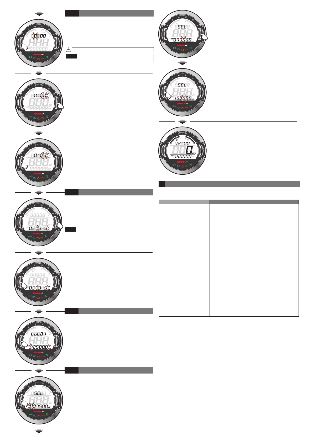
SETTING SCREEN INSTRUCTION
3-6
3-7
●When Battery Level remain 1 level, the Battery
symbol will flashing as warning.
MAIN FUNCTION SWITCH INSTRUCTION(SELECT BUTTON)
RPM FUNCTION INSTRUCTION
If you don’t install the fuel wiring, the fuel /
remaining distance will not display, can
change to the odo screen.
If you don’t install the volt wiring, the volt
will not display
NOTE
NOTE
Remaining Mileage might have difference between actual
mileage and calculated mileage according to the road condition, vehicle
condition, riding method and so on. Thus the Remaining Mileage is only a
suggesting reference to the rider
DC 12V