When the appliance is mounted on the wall, water pipes
fromthe central heatingsystem canbeconnected asshown
in Fig 6. The water pipes can be brought to the appliance
via the floor or from the wall. The appliance is supplied
with 15mm copper piping. If required balancing valves are
requiredthese canbe placedonto thepipework closeto the
appliance. Ensure all water fittings are secure before filling
the central heating system. Fill the central heating system
and check for leaks. To aid commissioning the appliance is
fitted with a bleed valve as shown in Fig 3. Open this valve
to release any air in the system. Start the circulating pump
and bleed again if necessary.
The appliance can also take pipes from a number of other
routes, refer to Fig 6 for more details.
Maximum water supply conditions are 85°C and 10bar
(1.0MPa).
Power supply connection
Beforecommencing theelectrical connection,it isessential
thatthe plumbingconnections havebeen checkedfor leaks
and that the appliance is dry.
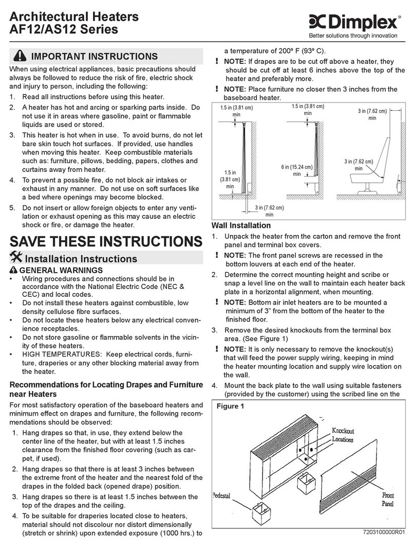
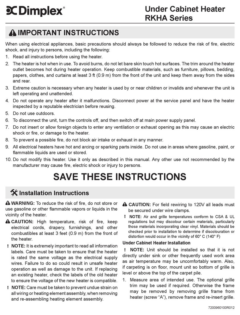
WARNING: THIS APPLIANCE MUST BE EARTHED
This heater must be used on an AC~ supply only and the
voltage marked on the heater must correspond with the
supply voltage.
The installation of this appliance should be carried out by
anelectrician orcompetent personin strictaccordance with
the current IEE Wiring Regulations and relevant Building
Regulations.
Before undertaking installation work, ensure the electricity
supply is disconnected from any relevant wiring. The
applianceis fittedwith 1meter offlexible cable4 x0.75mm²
forelectrical connection.Thecable maybe usedto connect
the heater to the fixed wiring of the premises through a
suitable connection box. The supply circuit to the heater
must incorporate a double pole isolating switch having a
contact separation of at least 3mm.
See Fig. 5 for details on Wiring Diagram.
A – Watercoil
B – Timer Module (Optional)
C – Capacitor (SRX180 Model only)
D – Water Sensor
E – Air Sensor
F – Mains Cable
G – Earth
H – Main PCB
I – Controls PCB
M – Motor
R – Resistor
All wires must be connected so any movement of the
product does not cause a short circuit.
IMPORTANT: The wires in this mains lead are coloured in
accordance with the following code:
BROWN: LIVE – ‘L’
BLUE: NEUTRAL – ‘N’
BLACK: PILOT WIRE
GREEN & YELLOW: EARTH – ‘E’
Pilot Wire Connection
The BLACK control wire is designed to carry a signal
from ‘slot in’ or ‘wall mounted’ Dimplex programmers. If,
however a programmer is not being used, the pilot wire
shouldbeisolated inaccordance with thecurrent IEEWiring
Regulations.
IMPORTANT – DO NOT connect the BLACK pilot wire to
earth.
Careshould betaken withthe installationof thepilot wire(s)
as when switching to background (set back) they become
energised at 240V although only at a current of less than
100mA. In every case a suitable means of isolation must
be provided for the pilot wire and marked to indicate that
two sources of supply may be present at the heater. Where
pilotwires areinstalled separatelyfrom theheater finalsub-
circuitthey should be protected, doubleinsulated andcarry
their own integral earth continuity conductor.
Replace the Front Cover
When the appliance is plumbed to the central heating
system and wired to a suitable socket outlet, replace the
frontcover.Ensure thetwo M5foixing bolts arereplaced as
shown in Fig 2. Turn on the supply to the appliance. Check
the operation of the appliance.
Operation
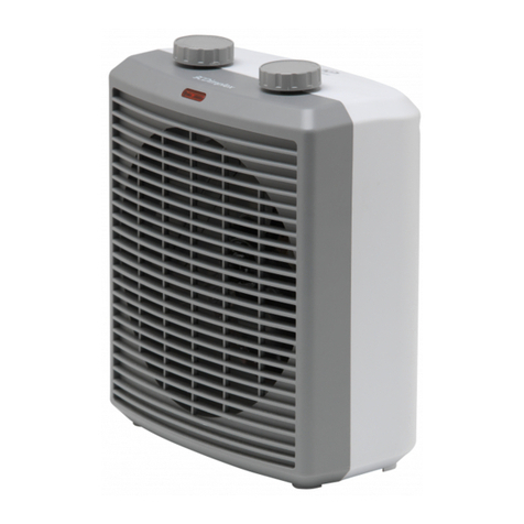
The controls are shown in Fig 4. Press the button to
activate the appliance.
Manual Mode
In manual mode, any fan speed can be selected. Press the
button to switch between fan speeds to give the desired
output. Set the desired room temperature level using the
centre dial. This provides the optimum power output based
on the room temperature.
During this setting the Manual Mode LED will illuminate.
Eco Mode
Eco mode allows the appliances to take in signals from an
optionalplug-in timerand/ora pilotwire controlsystem.This
mode allows the appliance to operate at certain periods of
the day/week using a plug-in timer or allows a number of
appliances be controlled from a single control point using
the pilot wire controller. During eco mode the Eco Mode
LED will illuminate.
Red indicates that the appliance is operating at comfort,
and green indicates the appliance is operating at setback.
Note: If there appliance stops operating and the LED is
flashing,thismeansthat thewatertemperature in unsuitable
for the appliance. Check the operation of the heat source
and/or the circulation pump. See the Troubleshooting
section for more details.
