DINAMIC OIL SE35 User manual

Instruction manual
SE35
Original instructions in english
Winch code : 93 35 00 30 0L Edition : 04/2012
Manual code : M23

- 1 -
- Index
1 General informations ..........................................................................................................1.1
1.1 - Manufacturer's identification data............................................................................1.1
1.2 - Winch identification data .........................................................................................1.1
1.3 - Using this instruction manual ..................................................................................1.1
1.4 - Exclusion of responsibility .......................................................................................1.1
1.5 - Instructions for technical assistance .......................................................................1.2
1.6 - Receiving ................................................................................................................1.2
1.7 - Warranty..................................................................................................................1.2
1.8 - Standards and applied laws ....................................................................................1.2
1.9 - Safety symbols used in this manual ........................................................................1.2
2 Technical informations .......................................................................................................2.1
2.1 - Main parts and general winch description...............................................................2.1
2.2 - Description of machine functions ............................................................................2.1
2.3 - Permitted uses ........................................................................................................2.1
2.4 - Uses not permitted..................................................................................................2.1
2.5 - Environmental conditions ........................................................................................2.1
2.6 - Safety devices .........................................................................................................2.2
2.7 - Residual risks..........................................................................................................2.2
2.8 - Noise .......................................................................................................................2.2
2.9 - Electro-magnetic field..............................................................................................2.2
2.10 - Overall dimension....................................................................................................2.3
2.11 - Technical data .........................................................................................................2.4
2.12 - Declaration of conformity “CE” ...............................................................................2.5
3 Safety ...................................................................................................................................3.1
3.1 - General safety instructions......................................................................................3.1
4 Transporting, handling and installation ............................................................................4.1
4.1 - Packing the machine ...............................................................................................4.1
4.2 - Handling - Storage ..................................................................................................4.1
4.3 - Winch movement.....................................................................................................4.2
4.4 - Assembly on base plate ..........................................................................................4.2
4.5 - Installation ...............................................................................................................4.3
4.5.1 - Warnings .................................................................................................................4.3
4.5.2 - Hydraulic system.....................................................................................................4.3
4.6 - Hydraulic diagram ...................................................................................................4.4
4.7 - Checks ....................................................................................................................4.7
4.8 - Cable mounting .......................................................................................................4.8
4.4 - Pulleys.....................................................................................................................4.10
5 Information about adjustments .........................................................................................5.1
5.1 - Adjustments ............................................................................................................5.1
6 Start up information............................................................................................................6.1
6.1 - Start up ...................................................................................................................6.1
7 Maintenance information....................................................................................................7.1
7.1 - Warning...................................................................................................................7.1
7.2 - Maintenance schedule ............................................................................................7.1
7.3 - Cable.......................................................................................................................7.1
7.4 - Lubrication...............................................................................................................7.2
7.4.1 - Oil level check and oil replacement
(wiches series NP - NPA - A - S - SE - SW - SF)
....7.2
- Index

- 2 -
7.4.2 - Oil level check and oil replacement (
winches series
SR - SWR - SFR) ..................7.2
7.4.3 - Oil level check and oil replacement (
winches series
S - SE) ...................................7.3
7.4.5 - Gearbox grease lubrication(
winches series
P) ........................................................7.4
7.4.4 - Oil level check and oil replacement (
winches series SRD - SWD - WDD)
...............7.3
7.5 - Cleaning operations ................................................................................................7.4
7.6 - Scrapping and disposal...........................................................................................7.4
8 Problems and solutions .....................................................................................................8.1
8.1 - Troubleshooting.......................................................................................................8.1
9 Parts replacement ...............................................................................................................9.1
9.1 - Cable replacement ..................................................................................................9.1

UN02-0176LG
a
b
c
e
f
g
hd
1.2.1
- 1.1 -
1.1 - Manufacturer's identification data
DINAMIC OIL S.p.a.
Via Togliatti, 15
41030 Bomporto (Mo) - Italy
telefono 059/812611 - telefax: 059/812606
e-mail: [email protected]
- Plate details
a= Model
b= Serial nr.
c= Max. delivery
d= Max. pull
e= Code
f= Year
g= Max. speed
h= Hoisting pressure
Information
Under no circumstances must the data shown on the
identification plate be altered.
1.3 - Using this instruction manual
This manual contains the necessary information
enabling the operator to familiarize and correctly use
the winch (also simply described as “the machine”).
The information contained is intended for skilled op-
erators (1).
The original instructions are supplied by the manu-
facturer in English.
To fulfil legal or commercial requirements, the origi-
nal instructions may be supplied by the manufacturer
in other languages.
If there are any doubts, whatsoever, concerning the
correct interpretation of the instructions contained in
this manual, immediately contact the manufacturer
for any necessary clarifications.
To facilitate the consultation of the manual, it has
been divided into chapters of major concepts.
For quick searches please consult the index.
Reproduction or publication, in part or in whole, of
the information contained in this manual is prohib-
ited without written authorisation given by the manu-
facturer.
Using this instruction manual, for purposes other
than those described, without written authorisation
given by the Manufacturer, is prohibited.
Any violation will be prosecuted according to the
law.
1.4 - Exclusion of responsibility
The manufacturer is released from any responsibility
for damages deriving from:
- incorrect installation or which is not in accordance
with applicable laws;
- use of the machine by unauthorised and/or un-
trained personnel;
(1) Only experienced people having the proper technical ability
and knowledge of regulations and laws will be able to carry
out the necessary operations and to identify and avoid pos-
sible damages during handling, installation, operation and
maintenance of the machine.
General informations
1
1.2 - Winch identification data
- 1.2 -
1.5 - Instructions for technical assist-
ance
In case of machine malfunction or failure, for which
special technical assistance is required and for all
spare parts requests, contact directly the manufac-
turer or the Reseller by phone or fax.
1.6 - Receiving
If any damages, faults or missing pieces are noted,
contact Dinamic Oil S.p.a. - Sales Office, immedia-
tely - Winch Department - by phone 059/812611 or
by fax 059/812606.
1.7 - Warranty
- Dinamic Oil S.p.a. warrants that its products are
free from all defects in materials or workmanship
during the warranty period indicated on the order
confirmation Dinamic Oil at the moment of pur-
chase.
- During the warranty period Dinamic Oil S.p.a. will
repair or replace all parts or components that are
unserviceable due to ascertained defects in mate-
rials or workmanship.
Under this warranty, any defective pieces must
be sent to Dinamic Oil S.p.a. which will examine
them so as to determine their cause.
- This warranty is strictly limited to the repair or re-
placement of products. Under no circumstances
will the manufacturer accept claims from customer
demanding reimbursement for direct or indirect
damages of any nature.
The merchandise may be returned only when pre-
viously authorized by Dinamic Oil S.p.a.
- This warranty does not extend to “O” rings or gas-
kets in general.
- This warranty does not cover any costs associated
with the installation or removal of defective parts
from the purchaser’s equipment.
- This warranty does not extend to any products that
have been repaired, modified or simply disassem-
bled, even partially.
1.8 - Standards and applied laws
The machine was designed and constructed under
current directives 2006/42/CE and the following
normes:
ISO 4301/01;
FEM 1001 3rd edition (point 2,3,4,5,8).
1.9 - Safety symbols used in this ma-
nual
The following symbols will also appear throughout
this instruction manual. For safety purposes, these
symbols aim to highlight the operations which are
considered safety hazards.Therefore, it is absolutely
indispensable that the instructions highlighted by
these symbols be respected.
The information and procedures indicated by this
symbol which are not strictly respected will result in
immediate death or serious personal injuries.
DANGER !!!
The information and procedures indicated by this
symbol which are not strictly respected may result in
death or severe personal injuries.
ATTENTION !!!
The information and procedures indicated by this
symbol which are not strictly respected may result in
minor personal injuries or damages to the machine.
CAUTION !!!
Information
Indicates important procedures and instructions.
- total or partial instruction disregarding;
- lack of maintenance;
- unauthorised modifications or repairs;
- non-designated uses;
- use of non-original spare parts and/or parts that
are not specific to the model;
- environmental circumstances beyond the manu-
facturer's control.
- This warranty does not extend to any products that
have been subject to misuse or abuse, incorrect or
careless assembly and tapering.
- This warranty recognized by Dinamic Oil S.p.a.
through its authorized sellers, disclaims all other
warranties of any nature whatsoever.
UN02-0349LG
AB
CD
E
2.1.1
- 2.1 -
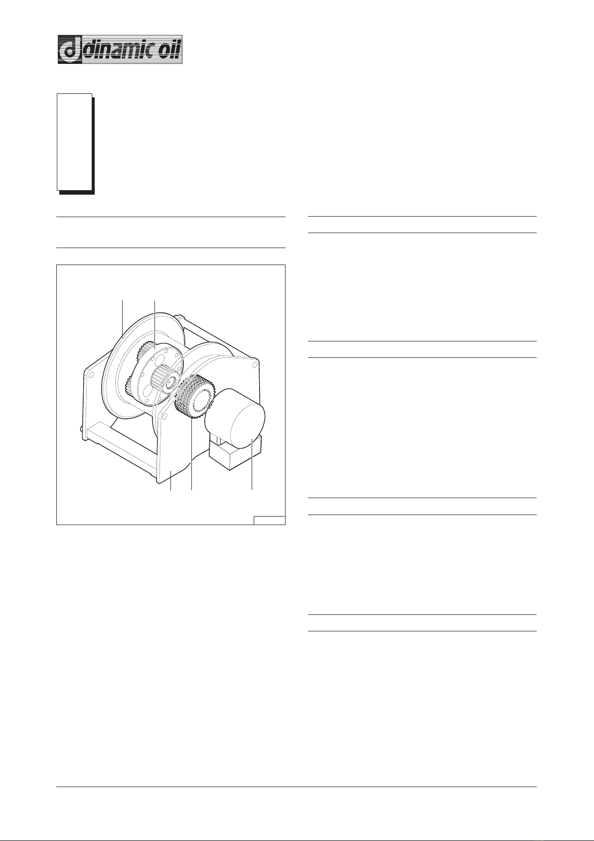
2.1 - Main parts and general winch de-
scription
- Legend
A= Hydraulic motor
B= Negative brake
C= Epicyclic reduction gear
D= Drum
E= Support structure
The winch is composed of a drum (in which an epi-
cyclic reduction gear and a negative brake are in-
serted) driven by a hydraulic motor, around which
the rope for load hoisting is wound: the whole unit is
installed on a support frame.
2.2 - Description of machine functions
The winch is commanded by the distributor of the
operative machine on which it is installed.
The rotation of the drum winds and unwinds the rope
to which the load is applied.
The brake is released when the motor is started and
is activated when the motor is stopped.
2.3 - Permitted uses
The winch is designed to raise and lower loads by
winding and unwinding the cable around the drum.
The use of the winch with superior values to those
listed in the technical data is considered "improper
use" and therefore "not admitted"; insofar the build-
er declines every responsability in relation to the
damages eventually provoked to people or to things
and cancels the guarantee.
2.4 - Uses not permitted
Never use the winch to lift and trasport people.
It is forbidden to use the winch before machine on
which it is mounted has been declared conforme to
the dispositions of the Directive 2006/42/CE.
2.5 - Environmental conditions
Room temperature for a proper use:
- 10°C; + 40°C.
Technical informations
2
UN02-0434LG
2.6.1
- 2.2 -
2.6 - Safety devices
Valve for stopping and controlling the down-
wards stroke
Fluid controlled, mounted directly on the hydraulic
motor, this part is essential for the safe functioning
of the winch. It prevents the load slipping out of the
motor’s control during lowering.
2.7 - Residual risks
Despite the observance of all safety norms and the
employment according to the rules described in the
manual, there can still be some residual risks among
which the most recurrent are:
- friction;
- crushing between rope and drum;
- inverse rotation of the drum by human error;
- ejection of fluids due to the spillage of the oil in
pressure.
Keep in mind that the use of an any machine impli-
cates some risks.
Face every type of operation with the maximum at-
tention and concentration.
2.8 - Noise
The level of noise emissions detected is not rel-
evant.
2.9 - Electro-magnetic field
The electro-magnetic discharges of the winch with
cable press - limit switch and load limiter are not si-
gnificant.

2.10.1
- 2.3 -
2.10 - Overall dimension
V2 (A) = Hoisting line: 3/4” BSP
V1 (B) = Lowering line: 3/4” BSP
D= Drain line: 1/4” BSP
P= Lubrication oil plug: 1/2” BSP

- 2.4 -
2.11 - Technical data
Rope layer n° 1 2 3 4 6
Line pull daN 4500
Rope speed with capacity 80 l/1’ m/1’ 25,5
Smooth drum rope capacity m18
4100
28
38
3800
30,5
60
3500
33
83
5
Grooved drum rope capacity
- Tightening torques
Values for driving torques (Nm)
Class 8.8 Class 10.9 Class 12.9
M10 50 73 86
M12 86 127 148
M14 137 201 235
M16 214 314 368
M18 306 435 509
M20 432 615 719
M22 592 843 987
M24 744 1060 1240
M27 1100 1570 1840
M30 1500 2130 2500
Hydraulic motor: SAUER DANFOSS OMTS
Motor displacement: 250 cm³
Maximum and minimum oil flow: 100/15 L/1’
Maximum counterpressure on the return line: 5 bar
Hoisting pressure: 210 bar
Safety brake: static torque of 120 daNm
(with back pressure of 1 bar)
Minimum brake release pressure: 2,5 MPa (25 bar)
Planetary reduction: ratio 1:11,5
Drum rotation direction (hoisting): counterclockwise
HLP ISO VG 46 lubrication oil: 6 L
Screw tightening torque (M18 - class 8.8): see “Tightening torques” chart
Total weight of winch complete with lubricant: 220 kg
Recommended rope diameter: 15 mm
The winch is classified according to UNI ISO 4301/1 norm

- 2.5 -
2.12 - Declaration of conformity “CE”
The picture shows a copy of the “CE” declaration of conformity; the original is issued by the manufacturer to-
gether with this manual.
------------------------------------------------------------------------------------------------------------------------------- -------
MANUFACTURER DECLARATION
------------------------------------------------------------------------------------------------------------------------------- -------
Company
DINAMIC OIL S.p.a con Socio Unico
Via Togliatti, 15
41030 Bomporto - MO
we declare on one’s own responsibility that the machine:
Winch Model
Registration number
Manufacturing year
Complies to the Directive 2006/42/CE, according to the article II B.
Norms of reference used: classification and dimensional norms FEM1.0013rd Edition
(dossier 2,3,4,5,8) and ISO 4301/01, general norms UNI EN 14492-1
It is forbidden to use the winch before the final machine it will be incorporated into conforms
to the above mentioned Directives.
Verify the working condition of the micro switch and end of line limit switch when present;
Verify the calibration of the load limit device under live load, when present, as per the instructions
in the maintenance and installation manual.
Name CARLO ALBERTO
Last name Ing. MONTECCHI
Position Legal representative
Bomporto lì,
Gen10
2.12.1

- 3.1 -
3.1 - General safety instructions
- Read this manual carefully before attempting installation, use and maintenance operations.
- The user must be familiar with applicable safety rules and use modes of both the operating machine and
the winch installed, as he is responsible for his own safety as well as for any other person present near the
machine working area.
- All the operators must be suitably trained to use, adjust and operate of both the operating machine and the
winch installed.
- Do not allow unauthorised personnel to use this machine.
- Do not start the machine, if it is faulty.
- Do not search for hydraulic leakage with bare hands, use a piece of paper or wood instead.
- A fluid coming from a very small hole might be almost invisible, and yet sufficient to penetrate the skin.
- If the fluid comes in contact with the skin, seek medical assistance immediately, for there might be risk of
infection or skin disease.
- Before removing any caps, plugs, or flexible tubes, make sure that there is no pressure in the hydraulic cir-
cuit.
Safety
3

UN02-0367BC
4.2.1
- 4.1 -
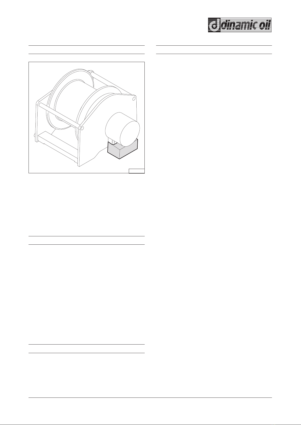
4.1 - Packing the machine
The packing of the machine is done according to the
agreements made with the Customer, taking into ac-
count the distance and type of transport chosen.
In general the winches are packed in wooden boxes
with wood joists to facilitate harnessing and lifting.
Packing varies in relation to the quantity and type of
product.
The weight and dimensions are indicated in the
transport documents or on the package itself.
4.2 - Handling - Storage
Do not tilt or turn the package upside down while lifting
or during transport.
ATTENTION !!!
Use suitable means of transport to hoist and move
the packed unit, taking into account the type of pack-
ing.
If the package is moved with a fork-lift truck, make
sure the weight is balanced on the forks.
If the packages are moved with a hoist and, in any
case, with a hook, make sure that the load is bal-
anced in the sling.
Use lifting accessories that are suitable and legally
certified.
While hoisting the unit and positioning it, take care
not to let it swing too much to prevent it hitting some-
thing.
The storage area must not be excessively damp or
dusty.
The room temperature must be between - 20 °C and
+ 70 °C with a maximum humidity level of 90%, with
no condensation.
Transporting, handling and installation
4
UN02-0494LG
4.3.1
UN02-0320MB
A
4.4.1
- 4.2 -
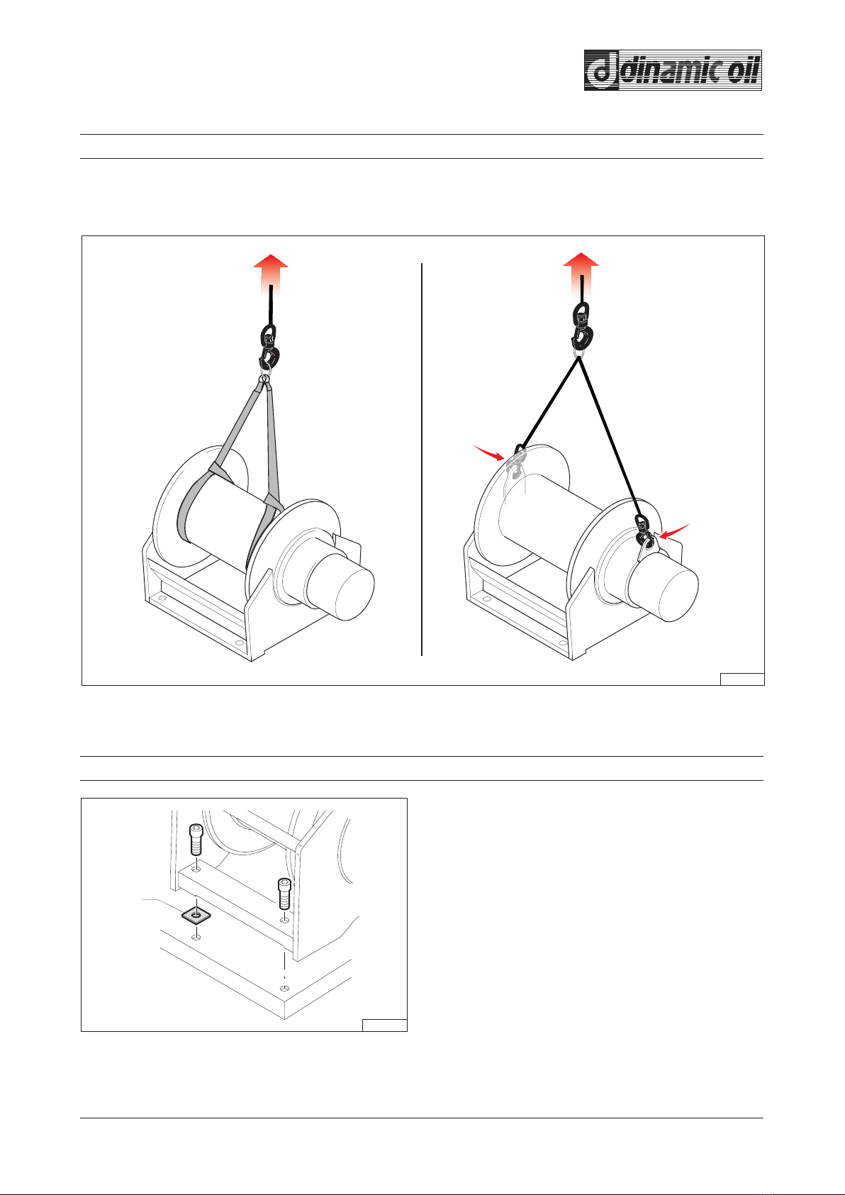
4.3 - Winch movement
4.4 - Assembly on base plate
For the hoisting procedures, strap the winch using two belts, which must be wrapped around the ends of the
drum (fig. A), or hook it on at the indicated points (fig. B) if present.
- Make sure that the surface the winch will be fas-
tened to is rigid enough and even.
- Place the winch on the surface and check that the
fastening plates lie perfectly flat on the fastening
surface.
- If one of the 4 weight bearing points of application
is raised, insert a shim "A" to balance the unit and
avoid causing the unit undue tension during screw
tightening.

UN02-0384FC
4.5.1
UN02-0319MB
AB
4.5.2
- 4.3 -
4.5.2 - Hydraulic system
The distributor, therefore, must have an open centre
(fig. 4.5.2) with an "H" configuration.
If the distributor presents a plurality of elements,
connect the winch to the last element closest to the
outfeed side.
Connect the delivery opening of the element to the
winch motor in position “V2”.
The hydraulic system must meet the applicable rules
and realised with proper hoses, filters and valves.
Before assembly, make sure the winding direction of
the rope corresponds to the one indicated by the ar-
row applied on the winch (fig. 4.5.1).
Winches which rotate in the opposite direction to the
standard ones can be supplied on request (counter-
clockwise).
The winch can be mounted with the fastening sur-
faces facing downwards, upwards or in any other po-
sition between the two.
4.5.1 - Warnings
4.5 - Installation
Winch installation and post-installation checks must
be carried out according to the applicable rules in the
country where the machine is used.
ATTENTION !!!
UN02-0491LG
4.6.1
- 4.4 -
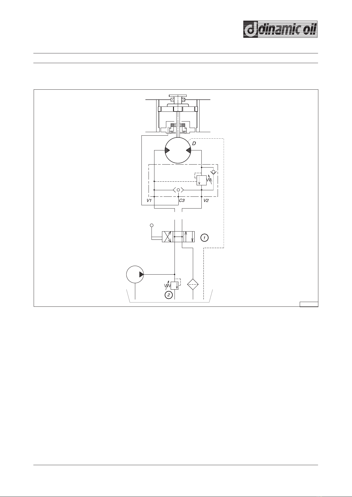
V1 = Lowering line
V2 = Hoisting line
C3 = Connection to brake
D = Connection of drainage unit
1= Open center valve
2 = Relief valve
4.6 - Hydraulic diagram
- Hydraulic diagram for winch without accessories

UN02-0372CC
4.6.2
- 4.5 -
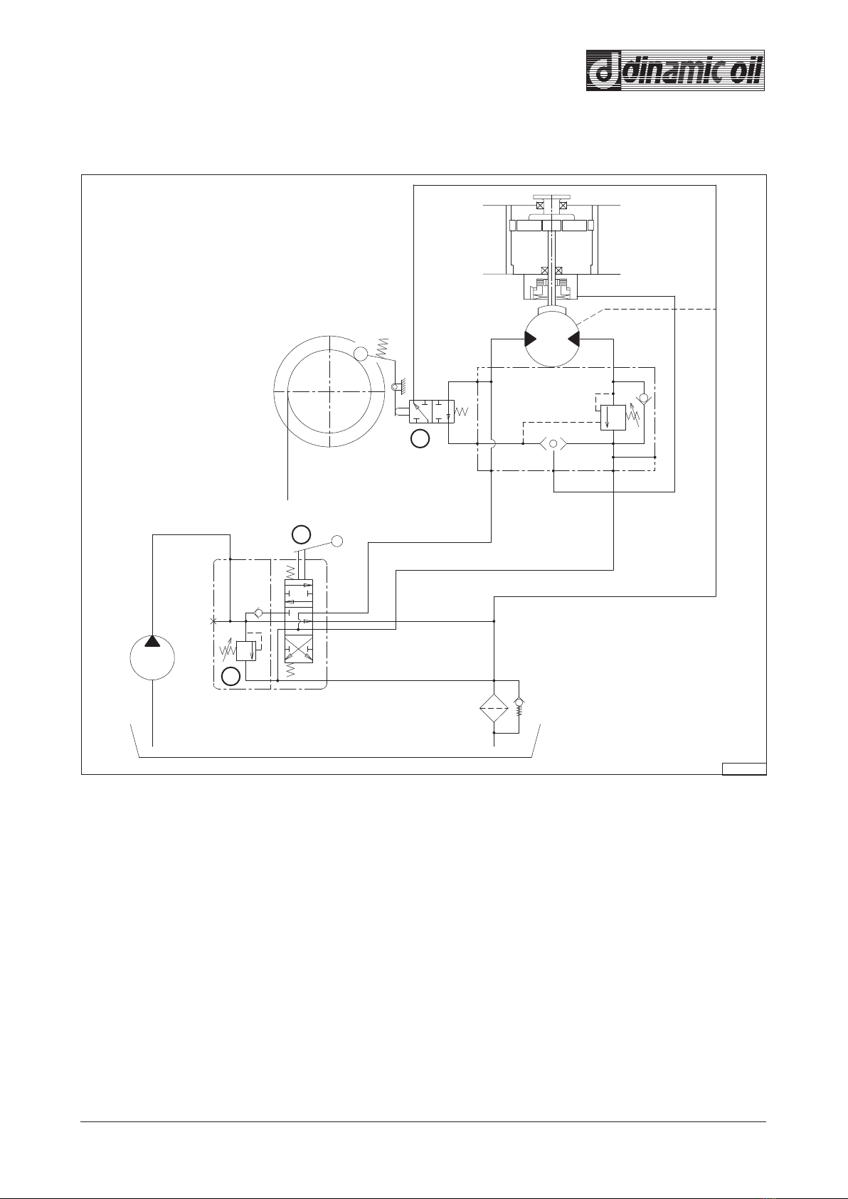
- Hydraulic diagram for winch with limit switch-electrical cable press (if present)
V1 = Lowering line
V2 = Hoisting line
C3 = Connection to brake
D= Connection of drainage unit
1= Open center valve
2= Relief valve
3= Discharge activation solenoid valve n.o
4= Resetting microswitch
5= Upwards stroke limit micro-switch
6= Downwards stroke limit micro-switch
7= Fuse
8= Limit switch activation key
LOWERING HOISTING
UN02-0417FD
V1 C3 V2
D
3
1
2
4.6.3
- 4.6 -
- Hydraulic diagram for winch with cable press - hydraulic limit switch (if present)
V1 = Lowering line
V2 = Hoisting line
C3 = Connection to brake
D= Connection of drainage unit
1= Open center valve
2= Relief valve
3= Lower stroke limit hydraulic valve

UN02-0369BC
M
V
R
D
P
m
4.7.1
UN02-0370BC
M
V
P
D
4.7.2
- 4.7 -
4.7 - Checks
- Check the pressure in the return line of the cir-
cuit
This measurement should be made by disconnecting
the two tubes from the valve and connecting them
with a “T” connection that may be linked to a pressure
gauge with a maximum scale of 60 bars.
Information
This counterpressure must be between 5 and 1
bars.
Counter-pressure values higher than 5 bar danger-
ously limit the breaking torque, and values lower
than 1 bar could cause an insufficient motor power
supply.
CAUTION !!!
D= Distributor
M= Motor
V= Valve
m= Pressure gauge
P= Pump
R = “T” connection
- Make sure the control distributor has the gate
open
D= Distributor
M= Motor
V= Valve
P= Pump
If you do not have sure indications you may proceed
as follows:
- disconnect the tubes from the valve and place their
ends in a container with a sufficiently large capac-
ity; start the pump while keeping the distributor in
the center.
- If the two tubes do not release oil into the container
the distributor has the gate closed; if instead the
two tubes release oil, the gate is open.
Make sure the oil flow does not cause the con-
tainer to overflow and as a consequence waste oil
as well as releasing polluting substances into the en-
vironment: if there is a risk of this occurring, interrupt
the test immediately and resume it only after having
replaced the container with a larger one.
CAUTION !!!
A
B
UN02-0328MB
4.8.1
- 4.8 -
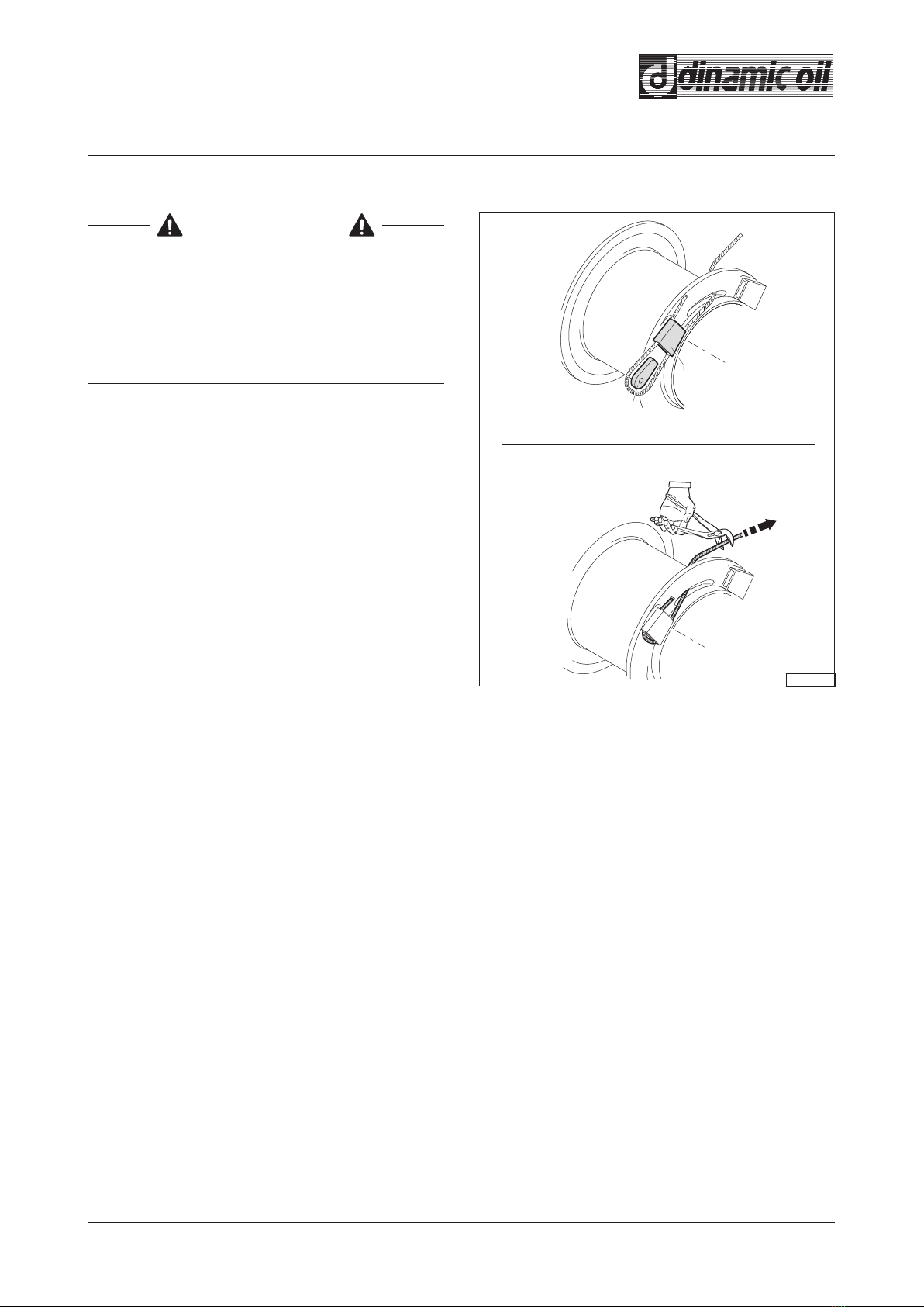
If the cable is not sufficiently compact during the ini-
tial assembly phase, when it is loaded it may become
caught up in the turns below and damaged.
1) Introduce the rope end into slot positioned on the
drum and then in the poket “A”.
2) Fold the rope around the thimble “B”.Then secure
the rope and thimble in the slot by pulling firmly.
The winding direction of the rope must correspond to
the drum rotation direction indicated by the arrow.
Make sure that the emergency switch is working and
that a skilled operator is on hand and ready to stop
the hoist in the event of entangling or other irregulari-
ties that may cause harm to the operator who is in the
vicinity of the cable.
ATTENTION !!!
4.8 - Cable mounting
- Installing cable with thimble

4.8.2
UN02-0427BE
B
A
- 4.9 -
- Installing cable with clamps
1) Place the end of the cable in the slot on the edge
of the drum and then in the clamps "A".
Minimum protrusion “B” from the last clamp equal
to 2 times the Ø of the cable.
2) Tighten the clamps screws.
Table of contents
Other DINAMIC OIL Winch manuals


Popular Winch manuals by other brands


SKYLOTEC
SKYLOTEC Jackpod Winch Instructions of use

HES
HES OzWinch Signature II Series owner's manual

Cycle Country
Cycle Country 25-3130 owner's manual

ADFINIS
ADFINIS SKYLOCK user manual

Come.up Winch
Come.up Winch DV-12 light manual

Farmi Forest
Farmi Forest W35R OPERATION, MAINTENANCE AND SPARE PARTS MANUAL


