Dini Argeo DFWIECEX User manual
www.diniargeo.com
DFWIECEX
ENGLISH
TECHNICAL MANUAL


33
4
4
5
6
6
8
49
8
50
9
50
51
7
8
43
52
47
53
49
56
10
7
42
12
49
39
38
42
14
43
5
34
47
5
42
Calibration
Equalisation
Safety
Communication
Approval
Reset
Quick calibration...........................................................................................................................................................
Complete calibration....................................................................................................................................................
Communication strings ...............................................................................................................................................
Communication commands........................................................................................................................................
Multi-channel connection............................................................................................................................................
Protection of the conguration menu via PIN..........................................................................................................
Conguration of the serial port for PC ......................................................................................................................
Approval seal.................................................................................................................................................................
Equalisation procedure ...............................................................................................................................................
Protection of the user menu via PIN .........................................................................................................................
Conguration of the serial port for printer ..............................................................................................................
Viewing the metrological version ...............................................................................................................................
Factory conguration reset.........................................................................................................................................
Complete memory reset .............................................................................................................................................
Wiring diagrams............................................................................................................................................................
TABLE OF CONTENTS
CONTENTS BY TOPIC
1. Introduction and warnings ........................................................................................................................
2. Technical features .......................................................................................................................................
9. Programming errors ....................................................................................................................................
10. Summary of the parameters ....................................................................................................................
3. Approval........................................................................................................................................................
4. Connections..................................................................................................................................................
5. Programming................................................................................................................................................
6. Communication strings...............................................................................................................................
7. Communication commands........................................................................................................................
How to access the programming menu......................................................................................................................
How to save the programming and exit the menu ...................................................................................................
Programming menu.......................................................................................................................................................
Single-channel.................................................................................................................................................................
Multichannel ...................................................................................................................................................................
8. Wiring diagrams ...........................................................................................................................................
CPU board .......................................................................................................................................................................
Display board ..................................................................................................................................................................
IECEX4IN4OUT option board ........................................................................................................................................
Optional boards..............................................................................................................................................................
11. FAQ - Frequently asked questions ...........................................................................................................
4
i
TECH_MAN_ENG_DFWIECEX_01.02_22.06
WARNINGS:
This product is the best solution for multifunctional weighing applications in Ex environments.
This manual provides an overview of the potentials of the product. The conguration menu can be used to adapt the product
functionality to the required weighing application.
Installation and electrical precautions to be followed are indicated in the Ex safety manual enclosed with the product.
IECEx marking
Ex ib [ib Gb] [ia Ga] IIC T4 Gb
Ex tb [ib Db] [ia Da] IIIC T135°C Db
Ta 0°C/+50°C
Atex marking II 2G, II 2D
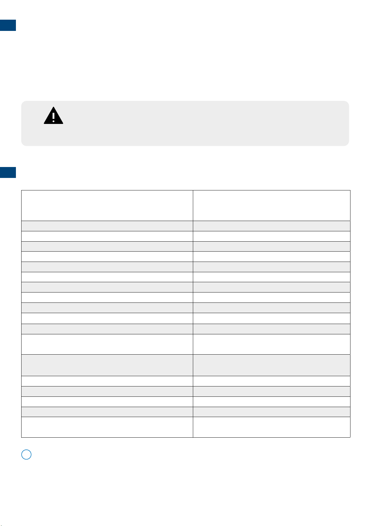
Power supply 6 - 9.6 Vdc (external power supply or battery)
Operating time (battery powered) up to 80 h
Analogue channels for load cell reading 4
Connectable cells 8, 350 Ω
Load cell power supply 5V
Converter XCore, up to 2600 conv./sec.
Maximum operating temperature range CE-M - OIML 0 °C + 40°C
Maximum operating temperature range 0 °C + 50°C
OIML divisions 10000e / 3x3000e (multi-range)
Divisions for internal factory use 100d... 800.000d
Optional Digital Relays (IECEX4IN4OUT or IECEX8OUT) 4 / 8 / 12
Ui: 18 V Ri: 214 Ω R input: 859 Ω
Optional Digital Inputs (IECEX4IN4OUT) 4 / 8
Ui: 18 V Pi: 1.75 W In: 70 mA
Optional analogue output 0 - 10 Vdc, 0 - 20 mA, 4 - 20 mA
Serial ports 485 1 standard, 2 optional (485IECEX)
Bluetooth wireless connectivity (BTH-IECEX) 1
Display High-contrast RGB with 6 digits, 25 mm high
Case Stainless steel, IP65
Dimensions: 280x143x185 mm
1. INTRODUCTION AND WARNINGS
2. TECHNICAL FEATURES
All communication interfaces are certied for use in hazardous areas
5
a. b.
d.
c.
e.
0.0
max
0
.0 0.0
2 sec
-off-
888888
x x.x x
x x.x x.x x
C
C
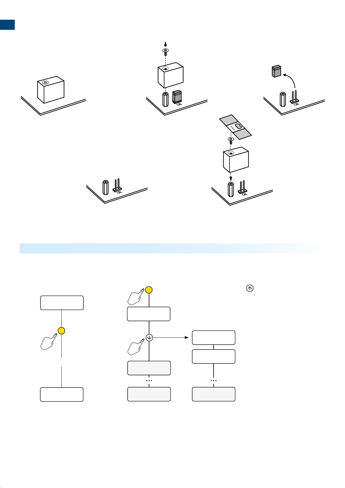
3. APPROVAL
Turn on the scale and press the key during display of the
power messages.
Metrological version
Weighing program version
1. Turn o the scale 2. Follow the procedure:
How to display the metrological version of the instrument

6
Cell 0.0
Junction
box
Cell 4 Cell 1
Cell 2Cell 3
0.0
DISPLAY BOARD
CONNECTOR
DISPLAY BOARD
CONNECTOR
DISPLAY BOARD
CONNECTOR
SENSOR
BLUETOOTH
(front side)
BOOT
REFERENCE
EXT KEYBOARD
SW2
I/O EXP
BUZZER
ON
SIG+ SIG- REF+ REF- EXC+ EXC- SIG+
SIG- EXC+ EXC- SIG+ SIG- EXC+ EXC- SIG+ SIG- EXC+ EXC-
CELL 1
CELL 2 CELL 3 CELL 4
J 1
J 1
Legal
Internal use
I/O BOARD - CLOCK - ALIBI MEMORY
ON ON
EXC+SEN+ SEN- EXC-
DISPLAY BOARD
CONNECTOR
DISPLAY BOARD
CONNECTOR
DISPLAY BOARD
CONNECTOR
SENSOR
BLUETOOTH
(front side)
BOOT
REFERENCE
EXT KEYBOARD
SW2
I/O EXP
BUZZER
ON
SIG+ SIG- REF+ REF- EXC+ EXC- SIG+ SIG- EXC+ EXC- SIG+ SIG- EXC+ EXC- SIG+ SIG- EXC+ EXC-
CELL 1 CELL 2 CELL 3 CELL 4
J 1
J 1
Legal
Internal use
I/O BOARD - CLOCK - ALIBI MEMORY
ON ON
EXC+SEN+ SEN- EXC-
TECH_MAN_ENG_DFWIECEX_01.02_22.06
Single-channel
Reference terminal block for 1-channel connection
Connect the scale to the main terminal block using the rst reading
channel of the A/D converter.
NOTES:
• For 6-wire connection with “Sense”, set the “REFERENCE” dip switches to OFF.
• For 4-wire connection, set the “REFERENCE” dip switches to ON.
Make connections with indicator o and power supply disconnected.
Observe the electronic specications in the Ex safety manual.
WARNING:
4. CONNECTIONS

7
Cell 1
Cell 2
Cell 3
Cell 4
0.0
DISPLAY BOARD
CONNECTOR
DISPLAY BOARD
CONNECTOR
DISPLAY BOARD
CONNECTOR
SENSOR
BLUETOOTH
(front side)
BOOT
REFERENCE
EXT KEYBOARD
SW2
I/O EXP
BUZZER
ON
SIG+ SIG- REF+ REF- EXC+ EXC- SIG+ SIG- EXC+ EXC- SIG+ SIG- EXC+ EXC- SIG+ SIG- EXC+ EXC-
CELL 1 CELL 2 CELL 3 CELL 4
J 1
J 1
Legal
Internal use
I/O BOARD - CLOCK - ALIBI MEMORY
ON ON
EXC+SEN+ SEN- EXC-
DISPLAY BOARD
CONNECTOR
DISPLAY BOARD
CONNECTOR
DISPLAY BOARD
CONNECTOR
SENSOR
BLUETOOTH
(front side)
BOOT
REFERENCE
EXT KEYBOARD
SW2
I/O EXP
BUZZER
ON
SIG+ SIG- REF+ REF- EXC+ EXC- SIG+ SIG- EXC+ EXC- SIG+ SIG- EXC+ EXC- SIG+ SIG- EXC+ EXC-
CELL 1 CELL 2 CELL 3 CELL 4
J 1
J 1
Legal
Internal use
I/O BOARD - CLOCK - ALIBI MEMORY
ON ON
EXC+SEN+ SEN- EXC-
NOTES:
• Set the “REFERENCE” dip switches to ON.
Reference terminal blocks for 4-channel connection
Multi-channel with digital equalisation
The 4 channels of the converter can be used to connect 2, 3 or 4 cells,
digitally equalising them without using junction boxes.
Make connections with indicator o and power supply disconnected.
Observe the electronic specications in the Ex safety manual.
WARNING:

8
0.0
max
0
.0
2 sec
-off-
888888
C
max
0.0
888888 ao ADVANC MoDE
save?
C
C C C
C
TECH_MAN_ENG_DFWIECEX_01.02_22.06
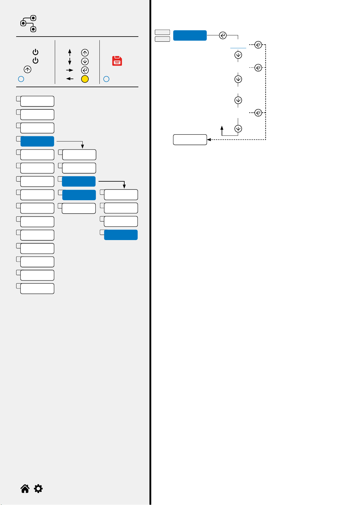
Press the key during display of the power messages.
PROGRAMMING
MENU
To save the programming changes made, repeatedly press the key browsing the menu in reverse, until the message SAVE?
appears: press to save or to exit without saving.
Example (read from right to left):
Save and exit
Cancel and exit
1. Turn o the scale 2. Follow the procedure:
C
C
5. PROGRAMMING
How to access the programming menu
How to save the programming and exit the menu

9
ao
SCee
ese
Sea
a
Ao
a
A.o
s
o
CA
e
0.C A
av
AvaC
10
11
11
12
19
27
28
29
29
30
32
33
34
34
35
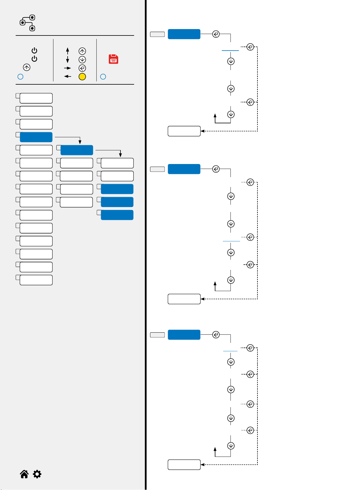
PROGRAMMING MENU
Print customisation................................................................................................................
Adjusting the display..............................................................................................................
Digital inputs...........................................................................................................................
Factory conguration reset..................................................................................................
Area of gravity of the place of use......................................................................................
Conguration of the serial ports........................................................................................
Weighing lter........................................................................................................................
Battery use...............................................................................................................................
Auto switch-o........................................................................................................................
Analogue output.........................................................................................................................
Digital outputs..............................................................................................................................
Diagnostics..............................................................................................................................
Advanced..................................................................................................................................
Parameter visible only under certain conditions.
Zeroing the pre-tare (zero calibration).............................................................................
Quick calibration....................................................................................................................
Parameter or menu subject to approval.

10
MENU
1. O =
=
=
=
2. On
3.
i i
C
A
B
C
D
E
F
G
H
J
K
L
M
N
O
I
av
ao
SCee
s
ese
Sea
e
a
Ao
A.o
o
a
AvaC
CA
CA
0.C A v
1
v
...
0 9
CapaC
oa
oa
-ok-
Ca.ok
0.0 0 1
200
000.000
...
000.000
...
0 9
-oK-
oa
0.0
A-1
kg
kg
kg
TECH_MAN_ENG_DFWIECEX_01.02_22.06
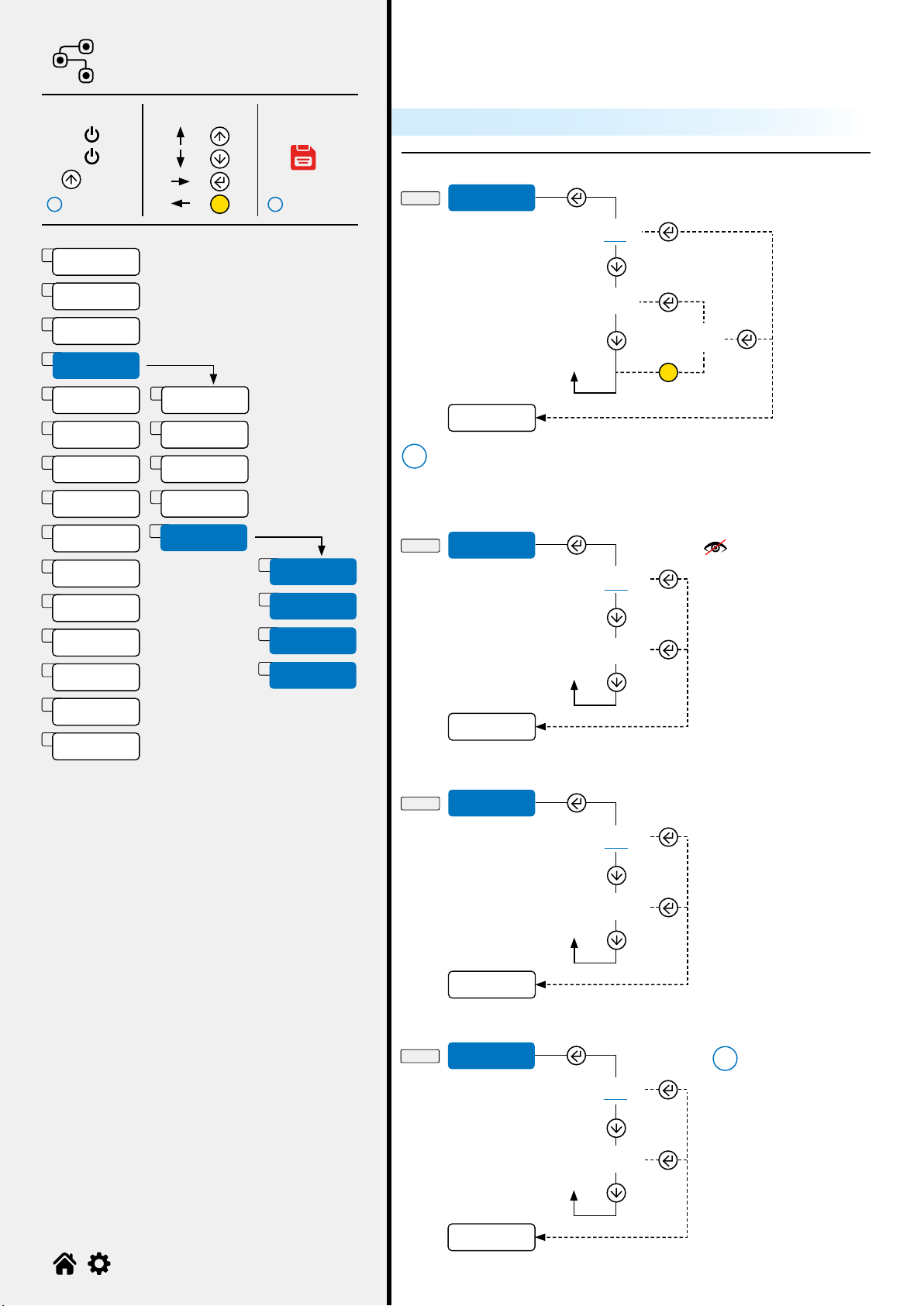
Quick calibration
Start of the calibration procedure:
Set the resolution and
press
How to set the value
How to set the value
or
Enter the calibration
weight and press
How to set the value
or
iIf an advanced calibration was performed
previously, step Ca will leads directly to
steps .
(See page 35)
Q-1 Q-2 Q-3

11
MENU
1. O =
=
=
=
2. On
3.
i i
C
A
B
C
D
E
F
G
H
K
L
M
N
O
I
J
0.C a
av
C
B
av
SEIA
0.C a
AV
...
0 9
se? -ok-
9.80390
av
ao
SCee
s
ese
Sea
e
a
Ao
A.o
o
a
AvaC
CA
0.C A
TECH_MAN_ENG_DFWIECEX_01.02_22.06
Zeroing the pre-tare
Area of gravity of the place of use
Once the calibration is completed, for proper operation set the area of
use in this pitch (if dierent from that of calibration).
Area of gravity
(9.75001...9.84999)
Acquisition of the zero point
How to set the value
or

12
MENU
1. O =
=
=
=
2. On
3.
i i
C
A
B
C
D
E
F
G
H
J
K
L
M
N
O
I
Com.SE
D-1-1 MoDE
sea
Com.C
.k
EE
mos
oE
Co
SaE
485
00
ax.1
ADVANC
Com.SE
pooC
I
Com.N
ax.2
AD
Com.C
MoDE
1
1
2
4
3
5
3
2
4
4
av
ao
SCee
s
ese
Sea
e
a
Ao
A.o
o
a
AvaC
CA
0.C A
AD
D-1-2 pooC
exe
sho
Csom
i
TECH_MAN_ENG_DFWIECEX_01.02_22.06
For repeater
For use by the
manufacturer
On demand (*)
On demand with code 485
(0...99)
Continuous transmission
(8 tx /sec)
Automatic stability
transmission
Transmission at the
pressure of
Conguration of the serial ports
Selection of the communication mode
Communication with PC, PLC or Repeater
Selection of the protocol:
For available protocols see page 43.
Visible only if
Moe = Co,
Sae or
p.k
13
MENU
1. O =
=
=
=
2. On
3.
i i
C
A
B
C
D
E
F
G
H
K
L
M
N
O
I
J
a
moe
D-1-3
D-1-4
D-1-5
Com.se
a
...
...
Com1
Com4
1200
900
115200
.8.1
.8.2
e.7.2
ooC
a
I
Com.SE
Com.C
MoDE
1
1
2
3
4
5
av
ao
SCee
s
ese
Sea
e
a
Ao
A.o
o
a
AvaC
CA
0.CA
...
ax.1
ADVANC
Com.N
ax.2
2
4
3
5
TECH_MAN_ENG_DFWIECEX_01.02_22.06
COM port selection for PC / PLC connection
Communication speed (Baud rate)
Conguration of the serial protocol
COM1, COM2 and
COM3 are physically
present on the
CPU board of the
indicator through the
expansion boards.
COM4 is used for
communication with
the Bluetooth BLE
module.

14
MENU
1. O =
=
=
=
2. On
3.
i i
C
A
B
C
D
E
F
G
H
J
K
L
M
N
O
I
1
2
D-2-3 a
pooC
D-2-1 MoDE
Com.
o C
Ee.
Co
SaE
ae
Cke
pooC
Com.N
Com.C
MoDE
1
2
3
4
5
6
av
ao
Sea
e
CA
0.C A
SCee
s
ese
a
Ao
A.o
o
a
AvaC
ax.1
ADVANC
ax.2
4
3
5
...
1200
115200
900
AD
D-2-2 pooC
exe
sho
Csom
i
Cs
powe.p
a
TECH_MAN_ENG_DFWIECEX_01.02_22.06
Communication speed (Baud rate)
For repeater
Thermal printer
Labeller
Continuous transmission
(8 tx/sec)
Automatic stability
transmission
Manual transmission
of string for PC when
pressing
Selection of the communication mode
Communication with printer or repeater or PC
Selection of the protocol:
For available protocols see page 43.
Visible only if
Moe = Co,
Sae or
p.k

15
MENU
1. O =
=
=
=
2. On
3.
i i
C
A
B
C
D
E
F
G
H
K
L
M
N
O
I
J
1
2Cs
powe.p
D-2-4
D-2-5
Cs
D-2-6 powe.p
...
.8.1
.8.2
e.7.2
Ih
o
o
Em
Cha 000
000me
pw.
Ex.off
o
moe
pooC
Cs
powe.p
Com.N
a
Com.C
MoDE
1
2
3
4
5
6
av
ao
Sea
e
CA
0.C A
SCee
s
ese
a
Ao
A.o
o
a
AvaC
ax.1
ADVANC
ax.2
4
3
5
TECH_MAN_ENG_DFWIECEX_01.02_22.06
Conguration of the serial protocol
Printer control signal
Free adjustment
For use by the
manufacturer
Printer power supply
from indicator via Vaux
connector.
Characters
sent (0...999)
Sending timeout (0...9999)
Printer power supply / Radio-frequency module
Only visible on models
tted with Vaux, ref. wiring
diagram (see page 45).

16
MENU
1. O =
=
=
=
2. On
3.
i i
C
A
B
C
D
E
F
G
H
J
K
L
M
N
O
I
1
2
AD
D-4-3
D-3-3 a
...
a
D-4-1
D-4-2
D-3-1
D-3-2
MoDE
pooC
ax.1
-
ax.2
p.k
epe.
Co
SaE
485
oe
1200
exe
sho
Csom
115200
i
pooC
a
Com.N
Com.C
MoDE
1
2
3
4
av
ao
Sea
e
CA
0.C A
SCee
s
ese
a
Ao
A.o
o
a
AvaC
900
ax.1
ADVANC
ax.2
4
3
5
TECH_MAN_ENG_DFWIECEX_01.02_22.06
Communication speed (Baud rate)
Selection of the communication mode
Selection of the protocol:
Auxiliary ports
For available protocols see page 43.
For repeater
On demand (*)
On demand with code 485
(0...99)
Continuous transmission
(8 tx /sec)
Automatic stability
transmission
Transmission at the
pressure of
Visible only if
Moe = Co,
Sae or
p.k
17
MENU
1. O =
=
=
=
2. On
3.
i i
C
A
B
C
D
E
F
G
H
K
L
M
N
O
I
J
1
Cs
D-4-4
D-3-4
...
.8.1
.8.2
e.7.2
pooC
a
Com.C
MoDE
1
2
3
4
av
ao
Sea
e
CA
0.C A
SCee
s
ese
a
Ao
A.o
o
a
AvaC
ADVANC
ax.2
4
5
2Com.N
ax.1
3
TECH_MAN_ENG_DFWIECEX_01.02_22.06
Conguration of the serial protocol
18
MENU
1. O =
=
=
=
2. On
3.
i i
C
A
B
C
D
E
F
G
H
J
K
L
M
N
O
I
1
2
3
4
5
.
D-5-1 e
eM
oe
D-5-2
D-5-3
.
eM
AvaC
o
yes
o
yes
C
Cf
1
2
3
4
ADVANC
Com.N
ax.1
ax.2
Com.C
av
ao
Sea
e
CA
0.C A
SCee
s
ese
a
Ao
A.o
o
a
AvaC
.? *
e
D-5-4 oe
No
yes
i
e
eM
oe
.
C
i
TECH_MAN_ENG_DFWIECEX_01.02_22.06
Activation of Bluetooth BLE module
TTL port / inclinometer activation (for use by the manufacturer)
Closing character of each print line
Advanced congurations
Only visible on DFWL
models.
Ignore unknown commands
When an unknown
command is sent:
- Selecting NO
will result in the
response “ERR04”.
-
Selecting
YES
ignores the
command (no
response).
* Bluetooth BLE
module initialisation
Refer to the AUX.2 port to communicate with the Bluetooth BLE module.

19
MENU
1. O =
=
=
=
2. On
3.
i i
C
A
B
C
D
E
F
G
H
K
L
M
N
O
I
J
HEADER
HEADER
HEADER
HEADER
WEIGHS N. 1
TICKET N. 15
GROSS
TARE
NET
24/12/2015 10:30
ayo
aa
heae
ehs
CoCk
ICKE
eND.IC
aC.p
aC.
aC.h
A
p.MA
HEADER
HEADER
HEADER
HEADER
...
.MA
AC.39
heae
aa
Cke
aC.39
e.C
aC.
ae
Cha
wehs
CoCk
Copes
aC.p
.e
aC.h
.save
aC.
es
a
1
2
3
4
5
6
7
13
8
14
9
15
10
16
11
17
12
18
av
ao
Sea
e
CA
0.C A
SCee
s
ese
a
Ao
A.o
o
a
AvaC
TECH_MAN_ENG_DFWIECEX_01.02_22.06
Additional parameters for label mode
Print customisation
Parameters for ticket/label mode

20
MENU
1. O =
=
=
=
2. On
3.
i i
C
A
B
C
D
E
F
G
H
J
K
L
M
N
O
I
Cha
Cha 2
Cha 2
E-1
E-2-1
E-2-2
a
Cha 1
1 x 1,5 mm
1 x 3 mm
1,5 x 2,5 mm
1,5 x 5 mm
2 x 3 mm
2 x 6 mm
3 x 4 mm
3 x 8 mm
4 x 6 mm
4 x 12 mm
...
E
ek
fo.1
fo.2
fo.3
fo.4
fo.5
fo.1
fo.2
fo.3
fo.4
fo.5
oma
oe
Cha 2
Cha 1
1
2
heae
aa
Cke
aC.39
e.C
aC.
ae
Cha
wehs
CoCk
Copes
aC.p
.e
aC.h
.save
aC.
es
a
1
2
3
4
5
6
7
13
8
14
9
15
10
16
11
17
12
18
av
ao
Sea
e
CA
0.C A
SCee
s
ese
a
Ao
A.o
o
a
AvaC
a
e
e
fa
espa
Ches
po
ek
TECH_MAN_ENG_DFWIECEX_01.02_22.06
Print language settings
Font dimensions
Main font
Label mode Ticket mode
See Cha 1
Other manuals for DFWIECEX
1
Table of contents
Other Dini Argeo Measuring Instrument manuals


