Salutron HardyTest HARTIP 1800 User manual

HARDNESS TESTER
HardyTest HARTIP 1800
OPERATION MANUAL


1
CONTENTS
1. FOREWORDS ..........................................................................................................................................2
1.1. HISTORY...................................................................................................................................................... 2
1.2. LEEB HARDNESS TEST (DEFINITION) .................................................................................................................. 2
1.3. NOTATION OF LEEB’S HARDNESS ...................................................................................................................... 2
2. FEATURES AND APPLICATIONS................................................................................................................3
2.1. INTRODUCTION............................................................................................................................................. 3
2.2. SPECIFICATIONS ............................................................................................................................................ 3
2.3. KEY FEATURES .............................................................................................................................................. 4
2.4. APPLICATIONS .............................................................................................................................................. 4
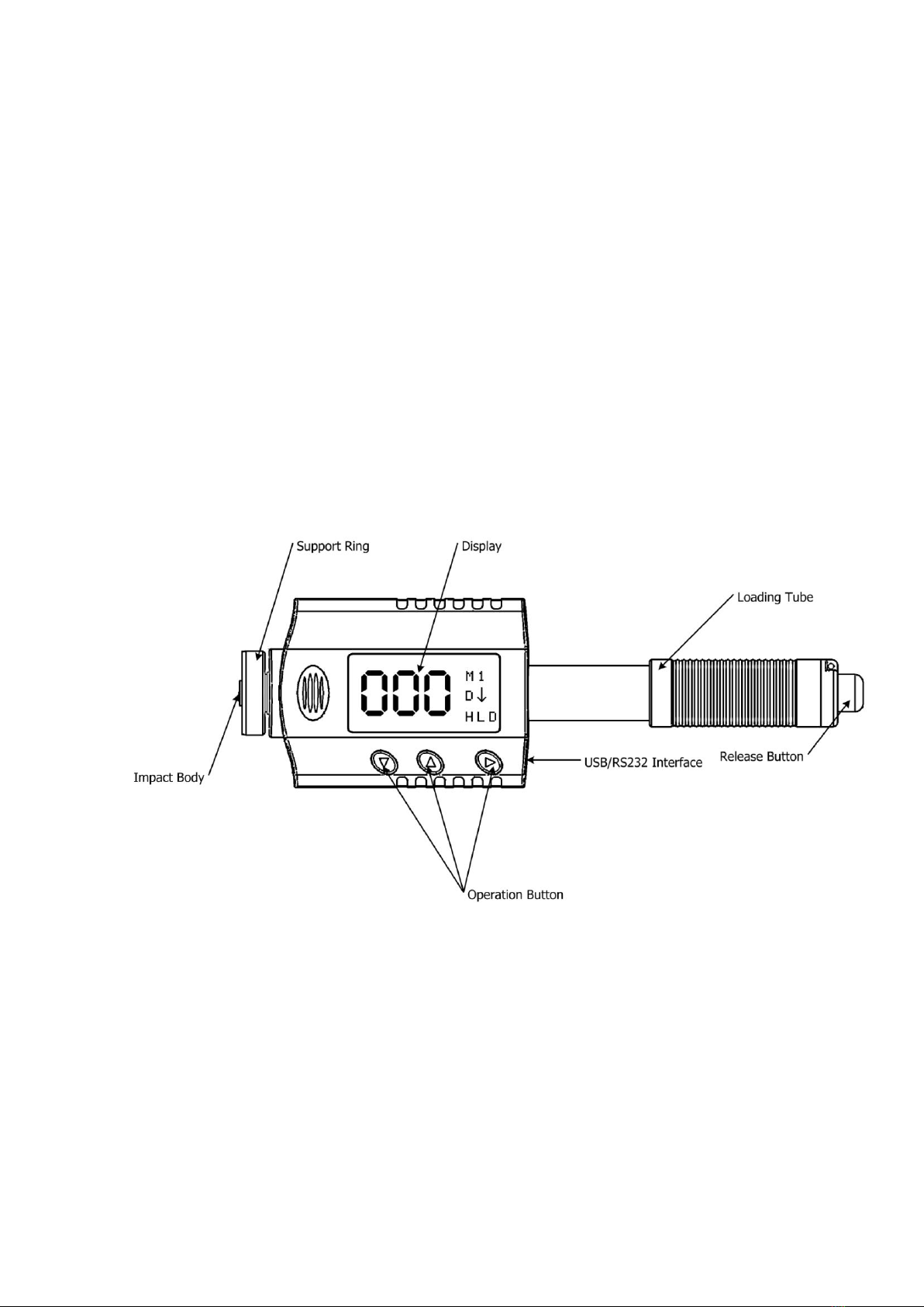
3. LAYOUT OF INSTRUMENT .......................................................................................................................4
4. SYMBOLS AND ILLUSTRATIONS...............................................................................................................5
4.1. SYMBOLS AND ILLUSTRATIONS ......................................................................................................................... 5
4.2. MEASUREMENT AND CONVERSION TABLE .......................................................................................................... 5
5. PREPARATION BEFORE MEASURING .......................................................................................................6
5.1. REQUIREMENTS FOR THE SAMPLE ..................................................................................................................... 6
5.2. REQUIREMENTS FOR THE WEIGHT OF THE SAMPLE................................................................................................ 6
5.3. REQUIREMENT FOR THE SURFACE HARDENED LAYER OF THE SAMPLE ........................................................................ 6
5.4. SURFACE OF THE TEST SAMPLE SHOULD NOT BE MAGNETIC. ................................................................................... 7
5.5. FOR TEST SAMPLE OF CURVING SURFACE ............................................................................................................ 7
5.6. SUPPORTING THE SAMPLES DURING TESTING...................................................................................................... 7
5.7. SAMPLES WITH CURVED SURFACES ................................................................................................................... 7
6. OPERATION ............................................................................................................................................8
6.1. BUTTON DESCRIPTION.................................................................................................................................... 8
6.2. DIAGRAM OF OPERATION ............................................................................................................................... 9
6.3. POWER ON THE INSTRUMENT ........................................................................................................................ 10
6.4. PARAMETERS SETUP..................................................................................................................................... 10
6.5. STATISTICS SETUP ........................................................................................................................................ 13
6.6. MEMORY SETUP ......................................................................................................................................... 14
6.7. DATA TRANSFER.......................................................................................................................................... 17
6.8. FUNCTION SETUP ........................................................................................................................................ 18
7. CHANGING IMPACT BODY ....................................................................................................................22
8. TAKE MEASURING.................................................................................................................................22
8.1. LOADING SPRING ........................................................................................................................................ 22
8.2. TAKE MEASUREMENT ................................................................................................................................... 23
8.3. RELEASE THE TESTING FORCE ......................................................................................................................... 23
9. MAINTENANCE AND REPAIR.................................................................................................................24
9.1. MAINTENANCE OF THE IMPACT DEVICE ........................................................................................................... 24
9.2. CHARGING BATTERY .................................................................................................................................... 24
9.3. SYSTEM RESET ............................................................................................................................................ 25
10. OPTIONAL ACCESSORIES ..................................................................................................................26
10.1. SUPPORT RINGS AND IMPACT BODY ................................................................................................................ 26
10.2. MICRO PRINTER.......................................................................................................................................... 26
11. PC SOFTWARE ..................................................................................................................................28
11.1. INSTALLATION OF HARDWARE DRIVER .............................................................................................................. 28
11.2. INSTALLATION OF SOFTWARE ......................................................................................................................... 28
11.3. OPERATION OF PC SOFTWARE ....................................................................................................................... 29
11.4. QUIT THE PROGRAM .................................................................................................................................... 36

2
1. Forewords
1.1. History
The Leeb measuring method was first brought into measurement technology in 1978. It
is defined as the quotient of an impact body’s rebound velocity over its impact velocity,
multiplied by 1000. Harder materials produce a higher rebound velocity than softer
materials. For a specific group of material (e.g. steel, aluminum. etc.), Leeb hardness value
represents a direct relationship to its hardness properties. For ordinary metal, conversion
curves of hardness HL versus other standard static hardness (HB, HV, HRC, etc.) are
available, enabling you to convert HL into other hardness values.
1.2. Leeb Hardness Test (definition)
An impact body with a spherical test tip made of tungsten carbide is propelled against the
sample surface by a spring force and then rebounds back. At a distance of 1mm from the
sample surface, the impact and rebound velocity of the impact body are measured by the
following method: A permanent magnet embedded in the impact body, when passing
through the coil in its coil holder, induces in the coil an electric voltage proportional to the
velocities of the magnet. Leeb hardness is expressed by the following formula:
1000*
Vi
Vr
HL
Where: HL is Leeb Hardness
Vris the rebound velocity of the impact body
Viis the impact velocity of the impact body
The voltage characteristic of output signal, when the
impact body passes through the induction coil is illustrated in the following figure:
Voltage characteristic of output signal
A Leeb’s Hardness Tester measures the hardness of sample material in terms of Hardness
Leeb (HL), which can be converted into other Hardness units (Rockwell B and C, Vicker,
Brinell and Shore D).
1.3. Notation of Leeb’s Hardness
When measuring the hardness of a sample material using the traditional static hardness
testing method, a change of applied pressure will result in a change in the hardness
reading. This will also happen during a Leeb’s Hardness test when one changes the
impact device. In hardness measurement of the same test sample with different impact
devices, the Leeb’s hardness values obtained will vary.
For example: 720HLD≠720HLC
Because different converting curves are obtained from different impact devices, when
converting hardness HL into another hardness values, the notation for the converted
hardness value should include the impact device used.

3
For example:
Hardness HRC converted from hardness L using impact device D should be written as 35,
9 HRCLD.
Where: 35=Hardness value HL
9=Hardness value HRC
L=Leeb’s Method
D=Impact device
2. Features and Applications
2.1. Introduction
This instrument is an advanced state-of-the-art palm sized metal hardness tester with
many new features which are light weight, easy operation, integrated design, high
contrast display, low operating temperature, auto compensating for impact direction and
etc. It can be widely used for measuring hardness of almost all ferrous and non-ferrous
metal materials for scale of Leeb hardness, Rockwell C, B &A, Brinell, Vickers, Shore and
Strength.
It has a memory capacity of 400 blocks and 360000 data which can be downloaded to
computer via USB or Bluetooth (Optional). The measuring value can be printed out from
tester to micro-printer by USB or Bluetooth. All stored data can be recalled and read on
the tester easily.
It also has a very unique feature, which impact device can convert between D and DL
simply by changing impact body. This two-in-one probe is equivalent to two individual
probes. With this optional accessory, you can take measurement at very narrow surface
such as slot bottom, gear tooth that probe D cannot match.
The 3.7V Li-ion rechargeable battery inside the tester can be charged via USB from PC or
via individual battery charger from mains wall power. With data software for PC,
customers can download measuring values from THE TESTER to PC and make process
such as save, delete, create testing report and export them to Excel.
2.2. Specifications
Principle: Leeb hardness measurement
Accuracy: +/-2HL (or 0.3%@HL=800)
Display: Digital with high contrast OLED
Display mode: Normal/flip or upward/downward
Hardness scale: HL / HRC / HRB / HB / HV / HS / HRA / σb
Measuring range: HL170-960 / HRC19-70 / HRB13-109 / HB20-665 / HV80-940 /
HS32-99.5 / HRA30-88
Impact device: D / D-DL 2 in 1 (Optional)
Materials: 11 common metal materials
Memory: 400 blocks and 360000 data can be saved and re-readable
Statistics: Average/Max/Min value can be calculated automatically
Interface: USB/RS232 for data transferring, printing or charging battery, Bluetooth for
data transferring and printing
Recalibration: allowed by user
Alarm: Up or down limit
Indicator: Low battery
Power supply: 3.7V Li-ion rechargeable battery
Power on/off: Auto
Operating environment: -40⁰C ~+70⁰C
Dimension (LxWxD): 148mm×44mm×22mm
Net weight: 110g
Standard: ASTM A956

4
2.3. Key Features
High accuracy: 0.3%
Integrated design: combine probe and processor into one unit
Two-in-one probe: D-DL convertible
Wide operating environment: -40 ºC ~+70 ºC
Auto turn on & off
High contrast OLED display: clearing at dark area
Friendly display style: normal/flip or upward/downward
Recalibration allowed by user
2.4. Applications
Hardness tests on installed machines or steel structures: e.g. on heavy and large
work-piece or on permanently installed system parts.
Rapid testing of multiple measuring areas for examination of hardness variations over
larger regions.
Measuring hardness for produced parts at production line.
Identifying metallic material stored in a warehouse.
Ineffectiveness analysis of permanent parts, pressure -vessel, turbo generator.
3. Layout of instrument

5
4. Symbols and Illustrations
4.1. Symbols and Illustrations
Symbols
Illustrations
HLD
LDL
HB
HRB
HRC
HS
HV
HRA
σb (N/mm2)
Leeb hardness value used with impact device D
Leeb hardness value used with impact device DL
Brinell hardness value
Rockwell B hardness value
Rockwell C hardness value
Shore hardness value
Vickers hardness value
Rockwell A hardness value
Strength value
4.2. Measurement and Conversion Table
Range for measurement and conversion:
IMPACT DEVICE D HLD: 170-960
MATERIALS
H R C
H R B
H B
H V
H S
HRA
σb
(N/mm2)
STEEL/CAST STEEL
20.0-67.9
59.6-99.5
80-647
80-940
32.5-99.5
30-88
375-1710
ALLOY TOOL STEEL
20.5-67.1
80-898
1170-2639
STAINLESS STEEL
19.6-62.4
46.5-101.7
85-655
85-802
740-1725
LAMELLAR IRON
21-59
24-100
93-334
90-698
NODULAR IRON
21-60
24-100
131-387
96-724
CAST ALUMINUM
24-85
30-159
22-193
BRASS
13.5-95.3
40-173
BRONZE
14-100
60-290
WROUGHT COPPER
14-100
45-315
FORGING STEEL
142-651
MILL ROLLER
140-651
30-99.5
IMPACT DEVICE DL LDL: 560-950
MATERIALS
H R C
H R B
H B
H V
H S
HRA
σb
(N/mm2)
STEEL/CAST STEEL
20.6-68.2
37.0-99.9
81-646
80-950
30.6-96.8
ALLOY TOOL STEEL
20.6-73.1
73-1184
NODULAR IRON
18.6-72.3
88-669
97-1167

6
5. Preparation before Measuring
5.1. Requirements for the sample
5.1.1. The surface temperature of sample should be less than 120 C.
5.1.2. The samples must feature a metallic smooth, ground surface, in order to eliminate
erroneous measurements brought about by coarse grinding or lathe scoring. The
roughness of the finished surface should not exceed 2μm.
5.2. Requirements for the weight of the sample
For samples weighing over 5 kg and of compact shape, no support is needed.
Samples weighing between 2-5 kg, and also for heavier samples with protruding parts or
thin walls, should be placed on a solid support in such a manner that they do not bend or
move by the impact force.
Samples weighing less than 2 kg should be firmly coupled with a stable support weighing
over 5 kg.
For coupling purposes,
The coupling surface between the sample and base plate should be flat, plane parallel and
ground.
A thin proper layer of coupling paste is to be applied to the contact surface of the sample.
The sample should be firmly pressed against the surface of the base plate by moving it
with a circular motion.
The direction of impact should be perpendicular to the coupling surface.
For the coupling operation, the following prerequisites must be fulfilled:
The contact surface of the sample and the surface of the base plate must be flat, plane
parallel and ground.
The direction of the test impact must be perpendicular to the coupled surface.
Minimum thickness of the sample for coupling (5mm).
Proper Coupling:
Proper coupling requires a little experience. Insufficiently coupled samples produce large
variations of individual measurements, L-values which are too low and the operation is
characterized by a rattling noise upon impact of the test tip.
Example for coupling a test piece with a base plate:
5.3. Requirement for the surface hardened layer of the sample
Surface -hardened steels and especially case-hardened steels produce L-values which are
too low when case-hardening depth is small because of their soft core. When measuring
Application of the coupling
paste (As thin as possible).
A particular advanced of coupling is
the possibility of obtaining a very
uniform, rigid connection between
the sample and the support, totally
eliminating stresses at the sample
surface. The resulting variation in
measured values is very low.
Mutual rubbing of both
parts while firmly press the
sample against the base
plate.

7
with impact device D/DL the depth of the hardened layer should be no less than 0.8 mm.
5.4. Surface of the test sample should not be magnetic.
5.5. For test sample of curving surface with radius of curvature R less than 30mm, a
small support ring should be used.
5.6. Supporting the Samples during Testing
Type of impact device
Classification of samples
heavy
medium-weight
light-weight
D/DL
more than 5 kg
2 - 5 kg
0.05 - 2 kg
When measuring hardness with this tester, the following has to be noticed: Despite the
low mass of the impact body and low impact energy, a relatively large impact force of
short duration is generated when the impact body hits the measuring surface. The max.
impact force of impact device D/DL is 900N.
For heavy samples of compact shape, no particular precautions are necessary.
Smaller and lighter samples or work pieces yield or flex under this force, producing
L-values which are too small and of excessively large variation. Even with big or heavy
work pieces it is possible for thin-wall regions or thinner protruding parts to yield upon
impact. Depending on the frequency of the resilient yielding action, the measured L-value
may be too small or too large. In many situations, potential problems can be checked in
the following manner:
a) Medium-weight samples and also heavier samples with protruding parts or thin walls
should be placed on a solid support in such a manner that they do not move or flex during
the test impact.
b) Light-weight samples should be rigidly “coupled” with a non-yielding support such as a
heavy base plate. Clamping in a vice is of no value, since the samples become exposed to
stress and because complete rigidity is never attained. As a rule, the measured L-values
would be too small and show excessive variations.
5.7. Samples with Curved Surfaces
Impact testers only work properly, if the impact body has a certain position in the guide
tube at the moment of impacting the test surface. In the normal position, automatically
present when testing flat and convex-cylindrical samples (such as round samples), the
spherical test tip is located exactly at the end of the guide tube.
However, when testing spherically or cylindrically shaped concave surfaces, the impact
body remains further within the guide tube or protrudes further therefore. Thus, with
such types of curved surfaces, it is to be observed that radii of curvature do not drop
below the values indicated in the following Fig.
Curved surfaces should always be tested with the small support ring.
Impact device types D Rmin=30mm
For impact devices D, special support rings are available to accommodate smaller radii on
convex or concave surface.

8
6. Operation
Figure 6-1 Display Description
6.1. Button description
▼:Downward button:
Move cursor downward or horizontal.
In measuring mode, shift single or duplex display mode or start to print a new page
while Bluetooth printing is on.
Delete current reading after set up statistics.
▲:Upward button:
Move cursor upward.
Change value or digit circulative from 0 to 9.
Shift normal or upright display mode.
►:Confirmation button:
Enter main menu.
Confirm the selected item.
▼&▲:Press downward and upward button simultaneously:
In measuring mode, turn on Bluetooth connection.

9
6.2. Diagram of Operation
Figure 6-2 Diagram of Operation

10
6.3. Power on the instrument
This tester has the function of auto power on while taking measurement and auto power
off after approx one minute of non-use.
To switch on the tester, push the loading tube toward tester until locking the impact body
inside the probe. Then let the loading tube back to original position. The instrument will
be powered on. The screen will show manufacturer’s logo for one second and then enter
the measuring mode, you can start measurement. At this moment, all parameters will be
performed by factory default (new tester) or by last setting up before closed.
Figure 6-3 Measuring mode
If parameters have been set, begin measurement at once. If changing parameters is
required, press the confirmation button ►on the keyboard to enter main menu.
Figure 6-4 Main Menu
After entering main menu, press▼or ▲button to move among the different options,
press ►button to enter/confirm this option. Once the parameters setup is finished, they
will be stored.
6.4. Parameters setup
All parameters can be selected or changed from the menu system by operator. By
pressing the three buttons (▼, ▲, ►) on the face of tester, you can easily change the
necessary parameters and activate the required functions by the logical, friendly menu
system; even you do not need to read the instruction.
Figure 6-5 Parameters Menu
6.4.1.Function of button
▼:Downward button:
Move cursor downward or horizontal.
In measuring mode, shift single or duplex display mode or start to print a new page
while Bluetooth printing is on.
Delete current reading after set up statistics.
▲:Upward button:
Move cursor upward.

11
Change value or digit circulative from 0 to 9.
Shift normal or upright display mode.
►:Confirmation button:
Enter main menu.
Confirm the selected item.
▼&▲:Press downward and upward button simultaneously:
In measuring mode, turn off Bluetooth connection.
6.4.2.Impact Device
This tester is equipped with internal D probe. The internal impact device can work as
standard probe when using impact body D, it can also work as special probe DL when
using impact body DL. Please set up Impact device to D while you are using probe D and
set up Impact device to DL while you are using probe DL.
Figure 6-6 Impact Device Selection
After selecting impact device, “Successfully” will be displayed on the screen, then return
to the Parameters menu.
Figure 6-7 Measuring mode with impact device D
Figure 6-8 Measuring mode with impact device DL
6.4.3.Materials selection
Material to be tested is prior to hardness scale. In another word, the material must be
selected properly when you want to have any hardness scale except HLD.
Choose Materials from parameters menu and press ►button to enter sub-menu. 11
materials will be showed in following three screens. Press▼or ▲button to move among
the different materials. Then press ►button to confirm it and return to parameters
menu.

12
Figure 6-9 Materials Menu
6.4.4.Hardness scale conversion
Choose Hardness scale from parameters menu and press ►button to enter sub-menu.
Press▼or ▲button to choose different hardness scales, then press ►button to confirm
the selection and return to parameters menu. Different hardness scales will show on the
screen depending on different materials. The default hardness scale is Leeb hardness
value (HLD).
Figure 6-10 Hardness Scale
6.4.5.Impact Direction
Choose Impact direction from parameters menu and press ►button to enter sub-menu.
Press ▼or ▲button to choose different impact directions. Then press ►button to
confirm the selection and return to parameters menu. The default impact direction is
downward.
Figure 6-11 Impact Direction

13
6.5. Statistics setup
Choose Statistics from main menu and press ►button to enter statistics menu. Press ▼
or▲button to choose the option to be set. Once the option is chosen, press ►button to
confirm this selection.
Figure 6-12 Statistics Menu
6.5.1.Mean time
Choose Mean time from statistics menu and press ►button to enter sub-menu. Then
press▼or ▲button to choose different mean times, then press ►button to confirm the
selection and return to statistics Menu. The default mean time is 0 time.
6-13 Mean Time
After setting the mean time, statistics information will be showed on the measuring mode.
When chosen display mode is different, the information showed on the measuring mode
is also different slightly.
Figure 6-14 Horizontal Display
Figure 6-15 Upright Display

14
6.5.2.Delete measured values
After mean time is set, in order to avoid the error caused by abnormal values involving in
calculation, you can delete the current values by following operation. Enter the upright
display mode, and then press ▼key to delete current measuring value. All measured
values from this time to NO 01 can be deleted one by one. If Memory is ON at this time,
corresponding measured values in memory block will also be deleted.
6.5.3.Upper limit
Choose Upper limit from statistics menu and press ►button to enter sub-menu. Press
▼or ▲button to choose the value of upper limit alarm to be set and press ▼button to
move the cursor to choose the digit required being modified. Press ▲button to modify
the value at the chosen digit (0-9 cycle) and press ►button to confirm the selection and
return to statistics menu. The default value of upper limit alarm is 999 (HLD) . When the
users set the value of upper limit alarm, the ranges of hardness values corresponding to
all hardness scales need be considered.
Figure 6-16 Upper Limit Alarm
6.5.4.Lower limit
Choose Lower limit from statistics menu and press ►button to enter sub-menu. Press ▼
or ▲button to choose the value of lower limit alarm to be set and press ▼button to
move the cursor to choose the digit required being modified. Press ▲button to modify
the value at the chosen digit (0-9 cycle) and press ►button to confirm the selection and
return to statistics menu. The default value of lower limit alarm is 150 (HLD).
Figure 6-17 Lower Limit Alarm
6.6. Memory setup
Choose Memory from main menu and press ►button to enter memory menu.
Press▼or▲button to choose the option to be set. Once the option is chosen, press ►
button to confirm this option.
Figure 6-18 Memory Menu

15
6.6.1.Memory on/off
Choose Memory on/off from memory menu and press ►button to enter sub-menu.
Press▼or ▲button to choose the option to be set and press ►button to confirm the
option.
Figure 6-19 Memory on/off Menu
Off: If this option is chosen, the instrument will not store measured values. After the
operation is successful, “Successfully”is showed on the screen of instrument. The screen
will return to the Memory menu in 1 sec. The default value is Off.
Current block: If this option is chosen, the instrument will store the measured value into
the current block. After the operation is successful, “Successfully”is showed on the
screen of instrument. The screen will return to the Memory menu in 1 sec. The current
block is storage block that is set by the user at the last time. If capacity of this storage
block is full, a new block will be created automatically after this block. The default
memory block is 001.
After Current block is set, current block No. and the measured value No. of this block will
be showed on the top of measuring mode, e.g. “B001 001”, indicating the first block and
the first measured value.
Select block: Press ►button to enter Select block window. On this window, the current
block can be set as any block of existing blocks. Press ▼button to move the cursor and
choose the value of modified group No., cycling from hundreds, tens, units to return in
turn. When the cursor is moved to the option of “Back”, by pressing ►button, the
instrument returns the memory menu. Press ▲button to modify the value at the chosen
digit (0-9 cycle). After setup is finished, press ►button to confirm the setup. After the
operation is successful, “Successfully”is showed on the screen of instrument. The screen
will return to the Memory menu in 1 sec. If group No. user chosen is beyond total group
No., “Block not exist”will be showed on the screen of the instrument. The screen will
return to the Select block Window in 1 sec.
Figure 6-20 Select block Window
New block: If this option is chosen, one new block will be created as current block. After
the operation is successful, “Successfully”is showed on the screen of instrument. The
screen will return to the Memory menu in 1 sec. Total 400 blocks can be created in the
instrument. 999 data can be stored in each block. When storage capacity of all blocks is
full, “Out of storage” will be showed on the screen of instrument. At this time, the users
can empty the memory or delete the memory blocks to release the storage space. Users
can view the storage status through System info.
If the users do not make any modification, they can press ▼and▲button simultaneously
to return the Memory menu.

16
6.6.2.Data recall
Choose Data recall from Memory menu and press ►button to enter the block no.
selection window. All blocks stored in the instrument are showed on the window; at most
9 block numbers are showed on each screen. “Change Page” is showed on upper left
corner. Displayed content can be changed by pressing ▼or ▲button. When the page of
block to be viewed is chosen, press ►button to change “Change Page” showed on upper
left corner into “Back”. Press ▼button to change the horizontal position of cursor and
choose the block number to be viewed. Press ►button to enter the Data recall window.
The window includes four-row three-column. The first row is used to show block number,
total pages and No. of current page. Measured values are stored from the second row to
the fourth row. Press ▼or ▲button to turn page forwards or backwards to view stored
measured values. At the same time, press ▼button and ▲button to show measured
value, hardness scale, material and impact direction alternately. Press the button once to
switch the content once and allow cycling switch.
On the Data recall window, press ►button to return the Block no. selection window. Press
Back to return to the Memory menu. Also at the same time press ▼button and ▲button
to return the Memory menu directly.
Figure 6-21 Data Recall
6.6.3.Delete block
Choose Delete block from Memory menu and press ►button to enter the block no.
selection window. All blocks stored in the instrument are showed on the interface. At
most 9 block numbers are showed on each screen. “Change Page” is showed on upper left
corner. Displayed content can be changed by pressing ▼or ▲button. When the page of
block to be deleted is chosen, press ►button to change “Change Page” showed on upper
left corner into “Back”. Press ▼button to change the vertical position of cursor and press
▲button to change the horizontal position of cursor. Choose the block number to be
deleted and press ►button. Confirmation screen will be showed on the instrument to
remind if this block is deleted. Confirm to delete this block and press ►button to delete it.
After the operation is successful, “Successfully”is showed on the instrument. Press ►
button to return the Block no. selection window. Press Back to return to the Memory
menu. Also at the same time press ▼and ▲button to return the Memory menu directly.
After the block is deleted, all data of this block is lost. Therefore, be cautious to this
operation. After deleting this block, its storage space can be set as current block for
continuous service.
6.6.4.Memory clear
Choose Memory clear from Memory menu and press ►button, a confirmation screen
will be showed on the instrument. Press ►button to confirm and empty the memory.
While empty the memory, the instrument will give the prompt “Please wait”. After the
memory is emptied, the instrument will give the prompt “Successfully”. Press▼button to
return the Memory menu.
After the memory is emptied, all blocks and data stored in the instrument will lose.
Therefore, be cautious to this operation.

17
6.7. Data Transfer
Choose Data Transfer from main menu and press ►button to enter Data Transfer
menu.
Figure 6-22 Data Transfer
6.7.1.Select port
Choose Select port from Data transfer menu and press ►button to enter Select port
menu.
Figure 6-23 Selecting communication port
There are two ways for communicating with PC or printing, one is by Bluetooth, and
another is by USB/RS232. Press ▼or ▲button to select different options and then press
►button to confirm.
Figure 6-24 Communicating by USB/RS232
Figure 6-25 Communicating by Bluetooth
Via USB/RS232 or Bluetooth interface, testing values can be downloaded to PC or printed
by micro-printer with our specified interface cable or via wireless connection. There are
two ways to transfer data. One is “on line” transferring. The testing values will be
transferred while taking measurement one by one. The other one is transferring from
memory.
NOTE: The Bluetooth function could also be turned on by pressing ▼and ▲button
simultaneously in measuring mode.
6.7.2.Transferring/Printing on line
Connecting the tester to PC or micro-printer with specified USB/RS232 cable or

18
Bluetooth connection.
Run software from PC or power on the micro-printer. (See 10.2 for micro printer
operations)
Taking measurement and the data will be downloaded to PC or be printed one by one.
Note: Please make sure the connection between PC and tester is successful. (See 11.3.2)
Under Bluetooth printing/communication mode, the first measurement is for active
Bluetooth communication, this test value might not be displayed, it is normal.
6.7.3.Transferring/Printing from memory
Connecting the tester to PC with accompanied cable or via Bluetooth.
Switch on the tester and enter main menu.
Setting communication port from “Data transfer” “Select port”.
Select “Data transfer” “Communicate”, and “Transferring Press any key back” will be
displayed which means the tester is in communication mode.
Please note all data transfer course must be under this mode. So please hold this mode
while data transferring. Once you quit this mode, you cannot do any data transfer except
normal measuring mode for transferring on line.
Start software on PC and operate the relative tool to download the data from memory.
Note: Please make sure the connection between PC and tester is successful. (See 11.3 )
6.7.4.Print block
Choose Print block from Data transfer menu and press ►button to confirm. Then the
instrument will enter print block interface. Please note before printing, you should select
printing port first. (Please refer to 6.7.1).
Figure 6-26 Printing block
Pressing button ▼, cursor will move between 0 0 1 and Back, the block no. can be
changed from 0 to 9 by pressing ▲button. After setting block no., press ►button to
print the data stored in the selected block.
Moving cursor to Back and press ►button, the current operation will be given up.
Note: The setting of “select port” function is only valid for current operation. When tester is
power off, the communication function will be turned off automatically. You should set it
again if you need to communicate or print.
6.8. Function setup
Figure 6-27 Function Setup
Choose function setup in main menu and press ►button to enter the function setup
menu. Press ▼or ▲button to choose the option to be set. Once the option is chosen,
press ►button to confirm this option.
This manual suits for next models
1
Table of contents
Other Salutron Measuring Instrument manuals