DINKO Instruments UV/VIS 6000 User manual

DINKO
INSTRUMENTS
User’s Manual UV/VIS 6000
1
UV/VIS 6000 Ultraviolet Visible Spectrophotometer
Smart Touch Screen
Reference Manual
Version: March 2021
Mark
c/ Encarnació, 123-125 / 08024-Barcelona
dinter@dinko.es www.dinko.es

DINKO
INSTRUMENTS
User’s Manual UV/VIS 6000
2
Dear user:
Thank you for purchasing and using the instrument of shanghai metash
instrument corporation. Please read the manual carefully to enable you to
know the performance of the instrument as soon as possible and to master
its using method.
The copyright of the manual belongs to shanghai metash instrument
corporation. Without the permission of our company, deleting and copying
of the contents in any form is forbad for anybody.
It is possible to modify the contents of the manual for the need of improving.
If any modification happens, please forgive us no further notice.
You can log on to our official website http://www.dinko.es for updates, or
call our hotline +34 93 284 69 62, to obtain the relevant advice and help.
Although we have checked this manual carefully, some mistakes cannot be
avoided, if any inconvenience is caused, please understand. If you find
some mistakes or have better suggestions, you are welcome to get in touch
with us to enhance our further improvement. we will actively adopt you
rational suggestions to ensure that our instrument will be improved
continually to meet your needs.

DINKO
INSTRUMENTS
User’s Manual UV/VIS 6000
3
Contents
1. Summary............................................................................................5
1.1 Working Principle .....................................................................5
1.2 Instrument Characteristics.........................................................6
1.3 Application Field.......................................................................7
1.4 Technical Parameters.................................................................8
1.5 Symbols and Prompt Notes .......................................................8
1.6 Brief Introduction of System and Structure ...............................9
2. Installation .......................................................................................10
2.1 Unpacking...............................................................................10
2.2 Installation Condition..............................................................10
2.3 Instrument Installation.............................................................12
3. Operating the Instrument..................................................................12
3.1 Power on Self-test ...................................................................12
3.2 Photometric Analysis...............................................................16
3.2.1 Photometric analysis.......................................................17

DINKO
INSTRUMENTS
User’s Manual UV/VIS 6000
4
3.2.2 Data processing ..............................................................18
3.3 Quantitative Analysis ..............................................................20
3.3.1 Standard curve test .........................................................21
3.3.2 Application of coefficient method .................................................29
3.3.3 Setting concentration unit..............................................................31
3.4 Spectral Scanning.......................................................................32
3.4.1 Wavelength scan................................................................34
3.4.2 Processing data................................................................374
3.5 Kinetic Analysis.......................................................................429
3.5.1 Kinetic analysis.................................................................41
3.5.2 Processing data................................................................462
3.6 System Settings........................................................................517
3.6.1 Lamps management............................................................ 48
3.6.2 Time Settings.....................................................................50
3.6.3 Dark current calibration...................................................561
3.6.4 Wavelength calibration....................................................572
3.6.5 System debugs.................................................................583

DINKO
INSTRUMENTS
User’s Manual UV/VIS 6000
5
3.6.6 Restoring defaults............................................................584
4. Routine maintenance........................................................................606
5. Troubleshooting ...............................................................................629
1.Summary
1.1 Working Principle
The working principle of spectrophotometer is mainly based on Lambert -
Bill law. When a bundle of monochromatic light passes through a uniform
colored solution, the absorbance of the solution is proportional to the
product of the concentration of the solution and the optical path,
which is
the true physical meaning of Lambert Bill's law. The law is the basis of
quantitative analysis of photometric analysis, and also the basic principle
of UV-Vis spectrophotometer. The formula for Lambert-Bill law is
expressed as follows:
A=k b C
A--The absorbance of the measured substance solution.
k-- Absorption coefficient of solution.
b--
The thickness of the liquid layer (the optical path of the cuvette or

DINKO
INSTRUMENTS
User’s Manual UV/VIS 6000
6
absorption pool), cm.
C—The concentration of the measured substance solution.
The premise of satisfying the Lambert Bill law is three hypotheses: First, the
incident light is monochromatic light. Second, the incident light is parallel light.
Third, light-absorbing particles are independent of each other, regardless of
quantity and variety. In addition, the deviation of the law is affected by sample
treatment, the optical path of measure, stray light, noise, the spectral bandwidth,
the chemical factors and other factors. The abovefactors need be taken into account
in the routine tests.
1.2 Instrument Characteristics
The characteristics of UV/VIS 6000 Spectrophotometer are the following:
The stray light is low and resolution is high in optical system, so the
stability and reproducibility are excellent and the readings are accurate.
The design is scientific, new technologies are used to combine the light,
instrument, electricity with computer to make the stability indicators of
the instrument close to or reach the high-level of UVspectrophotometer.
7 inch TFT capacitive touch screen, the touch point is more accurate,
sensitivity is more higher and stability is more better.
High definition resolution (800 * 480), fast running, large capacity for
picture.
Interactive and friendly user interface, and it is easy and fast to be used.
System settings function is powerful, the measurement function of

DINKO
INSTRUMENTS
User’s Manual UV/VIS 6000
7
photometric analysis, quantitative analysis, wavelength scan and
kinetic analysis can be realized without online operation.
Large data storage: 30 wavelength scan files, 20 kinetic measurement
files, multiple sets of measurement data and standard curves.
Data retrieval and atlas zooming function.
The universal printer (inkjet or laser) can be connected with the
instrument, A4 report output can be completed directly and the report
is more clear and beautiful.
USB transfer function can be achieved; data storage and reading is
more flexible.
1.3 Application Field
Ultraviolet visible spectrophotometer can be widely used in the fields of
pharmacy, medical and health services, chemical engineering, energy,
machinery, metallurgy, environmental protection, geology, food, biology,
materials, agriculture, forestry, fisheries and other industries, and plays an
important role in teaching and research of higher education, measurement
science and research institutes, quality control in the production, raw
materials and product analysis, and is commonly used in physicochemical
laboratory. UV/VIS 6000 is a UV spectrophotometer with touch screen.
The instrument is stable, accurate and powerful and has obvious

DINKO
INSTRUMENTS
User’s Manual UV/VIS 6000
8
advantages in the fields of scientific research and quality control.
1.4 Technical Parameters
Type UV/VIS 6
Wavelength range (nm) 19 -11
Spectral bandwidth (nm) 1,8 nm
Wavelength accuracy (nm) ± .5
Wavelength repeatability
(nm) ≤ .2
Photometric range -2 %T、- .3-3A、-9999C
Photometric accuracy ± .4 %T
Stray light ≤ . 7 %T
Size (mm) 46 ×38 ×18
1.5 Symbols and Prompt Notes
:
Power supply,
beware of electric shock.
: Heat source, burn carefully.
: UV light source, be careful radiation.
: Notice.
: Special note.
DINKO
INSTRUMENTS
User’s Manual UV/VIS 6000
9
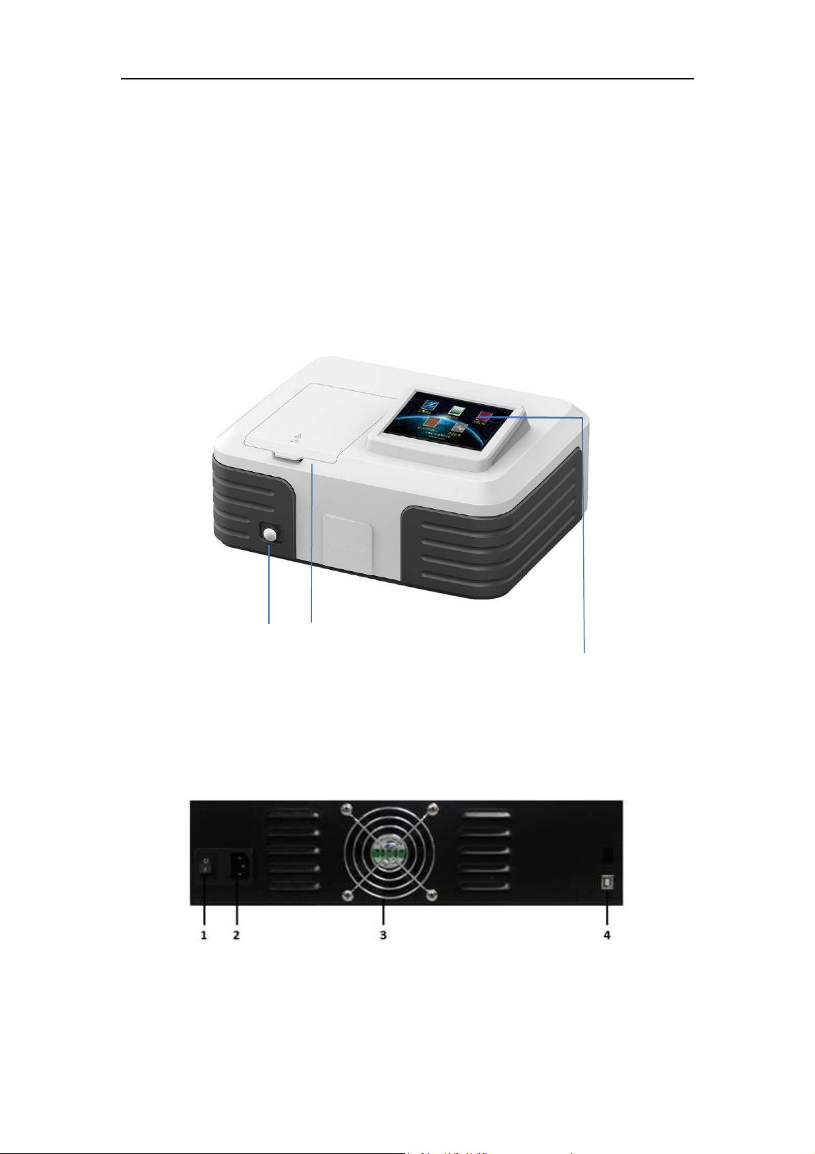
1.6 Brief Introduction of System and Structure
1、The shape and structure of the instrument
The shape and structure of the instrument is shown in figure 1:
1 2 3
1--Hand pull rod 2—Sample room 3--Touch screen
Figure 1 The shape of UV/VIS 6000
The back of the UV/VIS 6000 instrument is shown in figure 2:
1—Power switch 2-- Power supply socket 3-- Cooling vent
4-- Printer port

DINKO
INSTRUMENTS
User’s Manual UV/VIS 6000
10
Figure 2 The back of UV/VIS 6000
2.Installation
Please read the contents of this chapter carefully before installation.
2.1 Unpacking
Please check to make sure that the instrument external packing is intact and
has no opened marks before unpacking. After unpacking, please inspect to
make sure the instrument has no damage and the accessories is complete
by referring to the packing list in the manual (page thirty-fifth of this
manual). If you have any question, please consult the dealer or
manufacturer. If you find any damage or loss in the package, please inform
the manufacturer immediately.
2.2 Installation Condition
The following requirements should be met for the installation of the
instrument:
1) The requirements of temperature and humidity:

DINKO
INSTRUMENTS
User’s Manual UV/VIS 6000
11
The equipment should be placed in a dry room with temperature within
the range of 15 °C to 35 °C and relative humidity less than 85%.
2) Power requirements:
The rated voltage of the instrument is 220 V + 22 V AC (or 110 V + 11
V AC), the frequency is 50 Hz (or 60 Hz), and a good grounding wire
should be installed. More than 1000W electronic AC voltage stabilizer
is recommended to enhance the anti-interference performance of the
instrument.
3) Other working conditions:
A position not subject to strong vibration, or any continuous (even
weak) vibration.
A position not exposed to direct sunlight and disturbed by air flow.
A location free from exposure to corrosive gas, or dust.
A position free from strong magnetic, electromagnetic fields and
high frequency electromagnetic wave.
Make sure that the bench or table used to support the instrument is
comfortably able to withstand the load, more than 15 cm of space at
the rear away from the wall for effective ventilation.

DINKO
INSTRUMENTS
User’s Manual UV/VIS 6000
12
2.3 Instrument Installation
Installation procedures of the instrument are as follows:
1) Place the instrument on a stable bench after unpacking.
2) Connect instrument power cord. If equipped with a printer, connect
wiring between the instrument and printer and printer power cord.
3.Operating the Instrument
Please inspect all connections, ensure the connections are correct. The
power supply needs to meet the requirements and have reliable ground
connection. Ensure light path is expedite (no blocking object in sample
room). Ensure all other conditions are correct before the boot.
3.1 Power on Self-test
1. Powering on
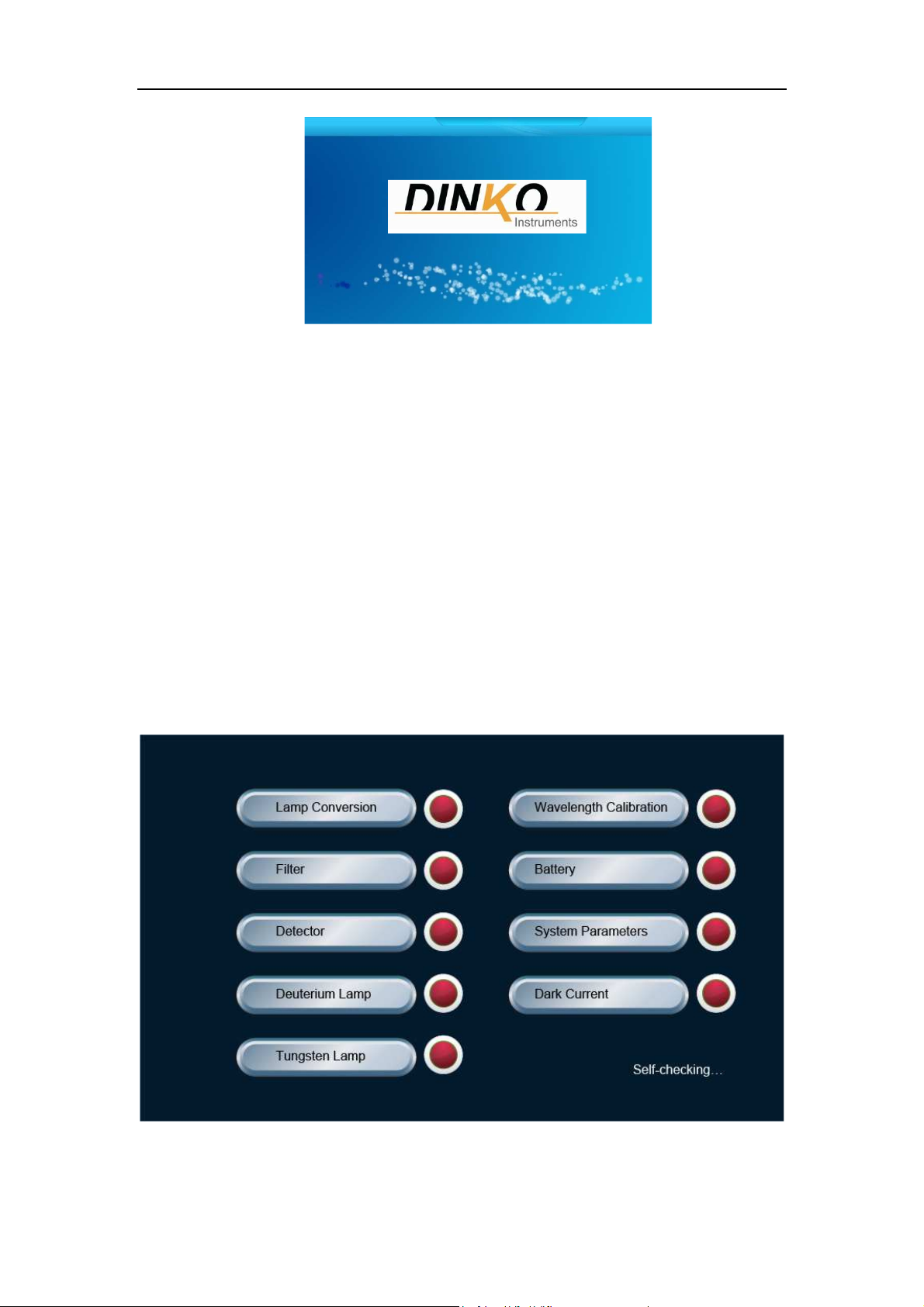
After the instrument is connected to power, start up the instrument and
the welcome interface is displayed, as shown in figure 3.
DINKO
INSTRUMENTS
User’s Manual UV/VIS 6000
13
Figure 3 The welcome interface
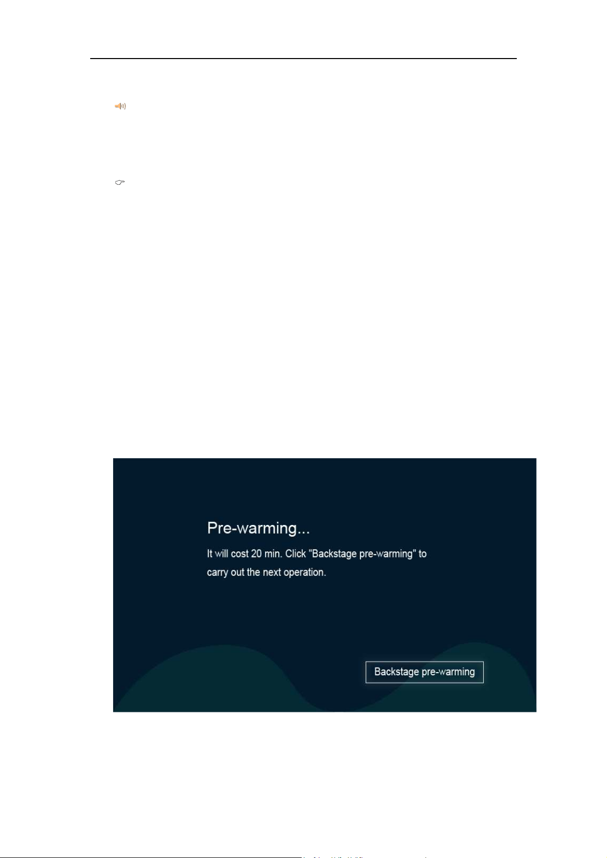
2. Self-check
The instrument starts self-check after displaying the welcome interface
several seconds. The lamp conversion, filter, detector, deuterium lamp,
tungsten lamp, wavelength calibration, battery, system parameters and
dark current are detected automatically. The self-check interface of the
UV/VIS 6000 Spectrophotometer is shown in figure 4.
DINKO
INSTRUMENTS
User’s Manual UV/VIS 6000
14
Figure 4 The self-checking interface
If the self-checking is passed successfully, the status indicator light is green. If
a self-checking error occurs, the buzzer alarm will automatically happen, the status
indicator light will be red, and the next self-checking content will be carried out
generally.
Please do not open the cover of sample chamber when self-checking. Please
contact the manufacturer in time, or judge and remove the fault according to the "5
common faults and exclusions" when the self-checking fails.
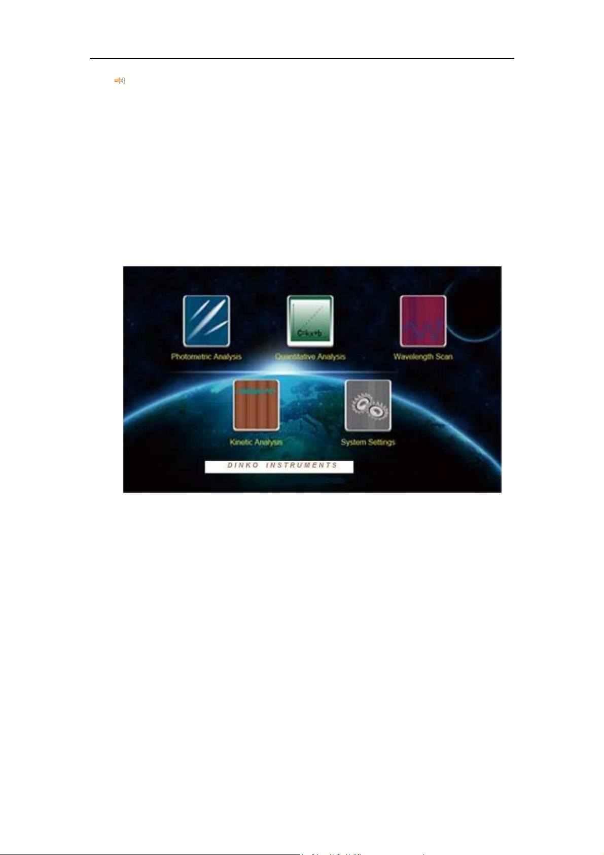
3. Pre-warming
Pre-warming starts after self-check (Figure 5).
The default time of pre-warming is 20minutes, the buzzing will appear
automatically and the instrument enters the main interface after pre-
warming.
Figure 5 Pre-warming interface
DINKO
INSTRUMENTS
User’s Manual UV/VIS 6000
15
The electronic components need to be preheated for a certain period of time to
reach a stable state after powering on the instrument. In addition, deuterium lamp
also takes some time to reach thermal equilibrium, so it is recommended that the
instrument starts to test after pre-warming for 20 minutes.
4. Pending operation
The main operation interface appears after pre-warming, as shown in
figure 6.
Figure 6 The operation main interface
Photometric analysis, quantitative analysis, wavelength scan, kinetic
analysis and system settings can be realized by the UV/VIS 6000. Click
the required functional modules, you can enter the corresponding
operation interface.

DINKO
INSTRUMENTS
User’s Manual UV/VIS 6000
16
3.2 Photometric Analysis
At the interface of photometric analysis, the user can measure the
absorbance, transmittance and energy at fixed wavelengths, and also print
the measurement results.
Click icon at the operation main interface to enter the interface of
photometric analysis (Figure 7).
Figure 7 The interface of photometric analysis
After entering the functional interface, the real-time display column is in
the upper part of the screen, the main area of the window is the data
recording area, and touch button operation area is on the right side of the
screen. The specifications of touch button are as follows:

DINKO
INSTRUMENTS
User’s Manual UV/VIS 6000
17
: used to set wavelengths.
: used to calibrate 0 Abs and 100%T, and correct the blank.
: used to measure and record data.
: to save data.
: to load and print data.
: to clear all displayed data.
: to quit the current interface and return to the last interface.
3.2.1 Photometric analysis
The specific steps of photometric analysis are as follows:
1) Entering photometric interface
Click icon at the operation main interface to enter the interface
of photometric analysis.
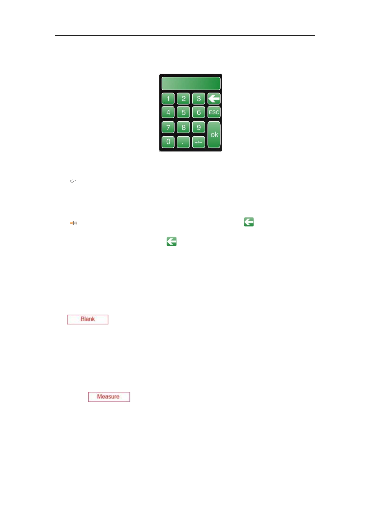
2) Setting test wavelength
Click button at the interface of photometric analysis, the
digital input window appears (Figure 8). Input the wavelength value,
click " " to confirm the value, the indication of "wavelength shift......"
appears below the screen, then the instrument reaches the specified
DINKO
INSTRUMENTS
User’s Manual UV/VIS 6000
18
wavelength.
Figure 8 Digital input window
The wavelength input range of the UV/VIS 6000 is 190 nm~1100 nm. If the
input value is out of the range, the data is considered invalid and needs to be
reentered.
If the input wavelength is found to be incorrect, click " " to clear the current
data and reenter. Touch button " " has the same function in the following data
input process.
3) Sample test
First, put the blank sample or reference solution in the optical path, click
button to set absorbance/ transmittance of the blank
sample or reference solution as 0 Abs/100.0%T at the current test
wavelength. Second, take out the blank sample or reference solution
from the optical path, put the determined solution into the optical path,
click button, then record the measured results of sample.
3.2.2 Data processing
The user can save, load, print and delete the data after photometric analysis.
DINKO
INSTRUMENTS
User’s Manual UV/VIS 6000
19
Save data: click button to save data to the host, and the data
is automatically saved to the USB memory if the USB memory is
connected.
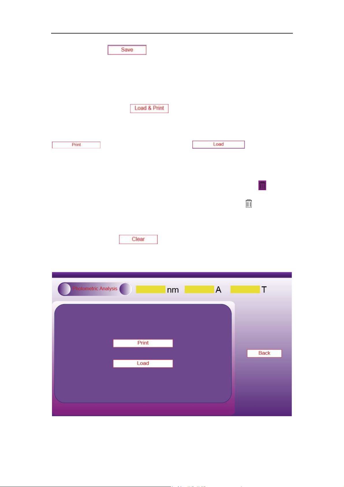
Load data, print: click button to enter printing and loading
data operations interface (Figure 9). When the printer is connected, click "
" to print the data, click "
" to open the
saved data. ".
Clear data: when the user needs to delete individual data, click icon at
the lower left corner of the screen to activate it (showing ), then click
the number of data needing to be deleted to delete the corresponding data.
Users can also click button on the right of the screen to empty
all data in the data table.

DINKO
INSTRUMENTS
User’s Manual UV/VIS 6000
20
Figure 9 Photometric analysis—the operation interface of printing and loading data
Once the user deletes the individual data, the clear touch button should be frozen
in time (click “ ” to make it show “ ”) to avoid misoperation in subsequent
operations. The delete operation is only valid for the current display, the saved data will
not be lost. If the user needs to save the deleted data, click button to
overwrite the saved data.
3.3 Quantitative Analysis
In the functional interfaces of quantitative analysis, users can use standard
curve method to determine unknown samples (The standard curves are got
through several standard samples, and unknown samples are measured by
comparing with standard curves). The unknown sample can also be
measured by the coefficient method (The slope and intercept of the
standard curve are known, and the unknown sample is measured directly
by this standard curve).
Click icon at the main operation interface of instrument
operation to enter interface of quantitative analysis (Figure 10).
Table of contents
Other DINKO Instruments Laboratory Equipment manuals


