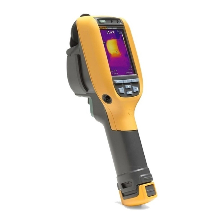
Fluke TIP900 User manual

Contacts
Fluke Process Instruments
Fluke Process Instruments North America
Santa Cruz, CA USA
Tel: +1 800 227 8074 (USA and Canada, only)
+1 831 458 3900
solutions@flukeprocessinstruments.com
Fluke Process Instruments Europe
Berlin, Germany
Tel: +49 30 4 78 00 80
info@flukeprocessinstruments.de
Fluke Process Instruments China
Beijing, China
Tel: +8610 6438 4691
info@flukeprocessinstruments.cn
Worldwide Service
Fluke Process Instruments offers services, including repair and
calibration. For more information, contact your local office or e-mail
www.flukeprocessinstruments.com
© Fluke Process Instruments
Specifications subject to change without notice.

WARRANTY
The manufacturer warrants this instrument to be free from defects in material and workmanship under
normal use and service for the period of two years from date of purchase. This warranty extends only
to the original purchaser. This warranty shall not apply to fuses, batteries, or any product which has
been subject to misuse, neglect, accident, or abnormal conditions of operation.
In the event of failure of a product covered by this warranty, the manufacturer will repair the instrument
when it is returned by the purchaser, freight prepaid, to an authorized Service Facility within the
applicable warranty period, provided manufacturer’s examination discloses to its satisfaction that the
product was defective. The manufacturer may, at its option, replace the product in lieu of repair. With
regard to any covered product returned within the applicable warranty period, repairs or replacement
will be made without charge and with return freight paid by the manufacturer, unless the failure was
caused by misuse, neglect, accident, or abnormal conditions of operation or storage, in which case
repairs will be billed at a reasonable cost. In such a case, an estimate will be submitted before work is
started, if requested.
THE FOREGOING WARRANTY IS IN LIEU OF ALL OTHER WARRANTIES, EXPRESSED OR
IMPLIED, INCLUDING BUT NOT LIMITED TO ANY IMPLIED WARRANTY OF MERCHANTABILITY,
FITNESS, OR ADEQUACY FOR ANY PARTICULAR PURPOSE OR USE. THE MANUFACTURER
SHALL NOT BE LIABLE FOR ANY SPECIAL, INCIDENTAL OR CONSEQUENTIAL DAMAGES,
WHETHER IN CONTRACT, TORT, OR OTHERWISE.
SOFTWARE WARRANTY
The manufacturer does not warrant that the software described herein will function properly in every
hardware and software environment. This software may not work in combination with modified or
emulated versions of Windows operating environments, memory-resident software, or on computers
with inadequate memory. The manufacturer warrants that the program disk is free from defects in
material and workmanship, assuming normal use, for a period of one year. Except for this warranty, the
manufacturer makes no warranty or representation, either expressed or implied, with respect to this
software or documentation, including its quality, performance, merchantability, or fitness for a particular
purpose. As a result, this software and documentation are licensed “as is,” and the licensee (i.e., the
User) assumes the entire risk as to its quality and performance. The liability of the manufacturer under
this warranty shall be limited to the amount paid by the User. In no event shall the manufacturer be liable
for any costs including but not limited to those incurred as a result of lost profits or revenue, loss of use
of the computer software, loss of data, the cost of substitute software, claims by third parties, or for other
similar costs. The manufacturer’s software and documentation are copyrighted with all rights reserved.
It is illegal to make copies for another person.
Specifications subject to change without notice.
The device complies with the requirements of the European Directives.
EC –Directive 2004/108/EC (EMC)
Electromagnetic Compatibility Applies to use in Korea only. Class A
Equipment (Industrial Broadcasting & Communication Equipment)
This product meets requirements for industrial (Class A) electromagnetic wave equipment and
the seller or user should take notice of it. This equipment is intended for use in business
environments and is not to be used in homes.

TABLE OF CONTENTS
1. SAFETY INSTRUCTIONS..............................................................................................................9
2. PRODUCT DESCRIPTION...........................................................................................................11
2.1 SYSTEM OVERVIEW AND ARRANGEMENT OF COMPONENTS..............................................................12
3. TECHNICAL DATA ......................................................................................................................16
3.1 SPECIFICATIONS ............................................................................................................................16
3.1.1 TIP900SYS (Thermal Imager, needs to be mounted in protective housing).......................16
3.1.2 TIP900SYS (Telescope Arms for Temperature Compensation Set)...................................18
3.1.3 TIP900SYS (IR Temperature Sensor, mounted close to kiln discharge) ............................19
3.1.4 TIP900SYS (IR Temperature Sensor Connection Box to network).....................................20
3.1.5 TIP900SYS (Protective Housing for Thermal Imager, Network, Power …).........................22
3.1.6 TIP900SYS (Option: Fiber Optic / RJ45 Ethernet Converter > 80m, 262ft) ........................22
3.1.7 TIP900SYS (Touch-Panel PC with industrial computer components).................................23
3.2 SCOPE OF DELIVERY......................................................................................................................24
4. INSTALLATION............................................................................................................................25
4.1 PRE-INSTALLATION TERMS AND CONDITIONS....................................................................................25
4.2 ENVIRONMENT...............................................................................................................................27
4.3 INSTALLATION OF PROTECTIVE HOUSING WITH INTERNAL THERMAL IMAGER......................................28
4.3.1 Mechanical Installation of the Protective Housing ...............................................................28
4.3.2 Electrical Installation of the Protective Housing...................................................................30
4.3.2.1 Cable Entry System........................................................................................................31
4.4 INSTALLATION OF THE TEMPERATURE COMPENSATION SET ..............................................................32
4.4.1 Mechanical Installation of the Temperature Compensation set...........................................32
4.4.2 Electrical Installation of the Temperature Compensation set ..............................................33
4.5 INSTALLATION OF THE DROP GATE IDENTIFICATION AND SIGNALING SET.............................................34
4.6 INSTALLATION OF THE INDUSTRIAL TOUCH-PANEL PC......................................................................35
4.6.1 Mechanical Installation of the Touch-Panel PC...................................................................35
4.6.2 Electrical Installation of the Touch-Panel PC.......................................................................38
5. OPERATION.................................................................................................................................39
5.1 SYSTEM PREREQUISITES,LIMITATIONS &GENERAL USER INFORMATION..........................................39
5.2 OPERATION OF TIP900 MONITORING AND DEFECT IDENTIFICATION SW.............................................40
5.2.1 General description, assigned screen areas, related elements & menus ...........................40
5.2.1.1 The program title & version line and the user mode dependent menu bar domain .......41
5.2.1.1.1 The program title line and its information content....................................................41
5.2.1.1.2 The “Product Recipe” selector in the menu bar .......................................................42
5.2.1.1.3 The “Edit Recipe” selector in the menu bar .............................................................45
5.2.1.1.4 The “Configuration” selector in the menu bar ..........................................................47
5.2.1.1.5 The “Maintenance” selector in the menu bar ...........................................................53
5.2.1.1.6 The “Show Fullscreen” selector in the menu bar .....................................................57
5.2.1.1.7 The “Login Supervisor” and the “Logout Supervisor” selectors ...............................62
5.2.1.1.8 The “About” selector in the menu bar ......................................................................62
5.2.1.2 The Board Map display domain......................................................................................63
5.2.1.3 The Process Screens display domain ............................................................................65
5.2.1.3.1 The Dryer Profile......................................................................................................65
5.2.1.3.2 The Boards display ..................................................................................................66
5.2.1.3.3 The Temperature display.........................................................................................67
5.2.1.3.4 The Reference Boards display.................................................................................68
5.2.1.3.5 The Horizontal Slice through the boards map..........................................................69
5.2.1.3.6 The Vertical Slice through the boards map..............................................................70

5.2.1.3.7 The Inspect Boards Map display ..............................................................................71
5.2.1.3.8 The Deck Statistics display.......................................................................................72
5.2.1.4 The Hardware Status Indicator display domain ..............................................................73
5.2.1.5 The Special Function selection display domain..............................................................73
5.2.1.6 The General Information display domain........................................................................74
5.2.1.7 The Deck History Information display domain.................................................................74
5.2.2 Operation in “Standard Operator” mode...............................................................................75
5.2.3 Operation in “Supervisor” mode ...........................................................................................76
5.3 OPERATION OF TIP900_LOGVIEWER ONLINE/OFFLINE VIEWING SW .................................................77
5.3.1 General description of the functionality and assigned screen elements..............................77
5.3.1.1 The program title & version line with the menu bar domain............................................78
5.3.1.1.1 The program title line and its information content ....................................................78
5.3.1.1.2 The File selector in the menu bar.............................................................................79
5.3.1.1.3 The Color Table selector in the menu bar................................................................87
5.3.1.1.4 The Map Data selector in the menu bar...................................................................88
5.3.1.1.5 The Dryer Profile selector in the menu bar...............................................................88
5.3.1.1.6 The Settings selector in the menu bar......................................................................89
5.3.1.1.7 The About selector in the menu bar .........................................................................89
5.3.1.2 The TIP900-LogViewer binary archive file table domain ................................................90
5.3.1.3 The TIP900-LogViewer board map inspector domain ....................................................90
5.3.1.4 The TIP900-LogViewer dryer deck specific reference board map display domain.........91
5.3.1.5 The TIP900-LogViewer dryer deck related archived board map display domain...........92
5.3.1.6 The TIP900-LogViewer historical board map temperature display domain....................92
6. CONFIGURATION ........................................................................................................................93
6.1 TIP900 HW CONFIGURATION .........................................................................................................93
6.2 TIP900 SW CONFIGURATION .........................................................................................................93
7. OPTIONS.......................................................................................................................................94
7.1 TIP900SYSPCST (PEDESTAL FOR TOUCH-PANEL PC) ..................................................................94
7.2 TIP900SYSPCAF (SWIVELING SUPPORTING ARM TOUCH-PANEL PC)............................................94
8. ACCESSORIES ............................................................................................................................95
8.1 TIP900-PCST (PEDESTAL FOR TOUCH-PANEL PC) ........................................................................95
8.2 TIP900-PCAF (SWIVELING SUPPORTING ARM FOR TOUCH-PANEL PC) ...........................................95
8.3 TIP900-HSFIC4 (HIGH SPEED FIBER OPTIC /RJ45 CONVERTER SET)............................................95
8.4 TIP900-ETHLTCB (7.5M,25FT ETHERNET CABLE,CAT5, 70°C)....................................................95
8.5 TIP900-ETHLTCB15 (15M,49FT ETHERNET CABLE,CAT5, 70°C).................................................95
8.6 TIP900-ETHLTCB30 (30M,98FT ETHERNET CABLE,CAT5, 70°C).................................................95
9. APPENDIX ....................................................................................................................................96
9.1 SOFTWARE INSTALLATION ON TOUCH-PANEL PC.............................................................................96

TABLE OF FIGURES
Figure 1: Example of fiber optical link to overcome large network distances........................................11
Figure 2: TIP900SYS system components, which have to be integrated .............................................12
Figure 3: Process Overview and Arrangement of TIP900 Components (red).......................................12
Figure 4: Front view of the Industrial Touch-Panel PC..........................................................................13
Figure 5: Rear view into the equipped Industrial Touch-Panel PC........................................................13
Figure 6: Options to fix the Industrial Touch-Panel PC .........................................................................14
Figure 7: Protective Housing, equipped with Thermal Imager and network components.....................14
Figure 8: Temperature Compensation Set ............................................................................................15
Figure 9: Drop gate identification and signaling set...............................................................................15
Figure 10: Thermal Imager mounting locations and dimensions...........................................................17
Figure 11: Thermal Imager air purge and water cooling connections ...................................................17
Figure 12: Sensor Telescope Arm for Temperature Compensation Set...............................................18
Figure 13: Counter Paddle Telescope Arm for Temperature Compensation Set .................................18
Figure 14: Dimensions of LTS10 Sensing Head ...................................................................................19
Figure 15: Spot Size Charts...................................................................................................................19
Figure 16: Dimensions of RAYMI3COMME Box ...................................................................................21
Figure 17: Terminal Wiring for the RAYMI3COMME Box .....................................................................21
Figure 18: Protective Housing for Thermal Imager, Network Components, Power Supply ..................22
Figure 19: Industrial cabinet for Touch-Panel PC and integrated components.....................................23
Figure 20: TIP900 Definitions for wallboard, image orientation and pixel numbering...........................26
Figure 21: TIP900 schematic wiring of concerned components............................................................27
Figure 22: Mounting of the Thermal Imager in the Protective Housing.................................................28
Figure 23: Loose supplied parts for mechanical installation support.....................................................29
Figure 24: Distance between Protective Housing and wallboard surfaces ...........................................29
Figure 25: Principle diagram of internal wiring in Protective Housing ...................................................30
Figure 26: Pictures and description of cable entry system....................................................................31
Figure 27: Upper and lower telescope arm fixtures installed after kiln exit...........................................32
Figure 28: Schematic of kiln and deck outfeed arrangement................................................................32
Figure 29: Drop gate identification and signaling set ............................................................................34
Figure 30: Schematic of drop gate wiring to identification and signaling set.........................................34
Figure 31: Base mounted pedestal with mounting dimensions.............................................................35
Figure 32: Wall mounted swiveling supporting arm with dimensions....................................................36
Figure 33: Load diagram for wall mounted swiveling supporting arm ...................................................36
Figure 34: Mounting elements for wall mounted swiveling supporting arm with dimensions................37
Figure 35: Wiring Terminal Block in Touch-Panel PC...........................................................................38
Figure 36: Created TIP900 icons during SW installation process.........................................................39
Figure 37: Program is running in supervisor mode, 7 domains are marked .........................................40
Figure 38: Program is running in Operator mode with restricted rights.................................................41
Figure 39: Program is running in Supervisor mode with administration rights......................................41
Figure 40: Product Recipe selection screen in Operator or Supervisor mode......................................42
Figure 41: Edit Recipe selection screen in Supervisor mode................................................................45
Figure 42: Application configuration tab screens in Supervisor mode ..................................................47
Figure 43: Inputs/Outputs & Temperature Compensation tab screens in Supervisor mode.................50
Figure 44: Scanner tab screen in Supervisor mode..............................................................................52
Figure 45: Input and Output module tab screen in Supervisor mode....................................................53
Figure 46: Maintenance of MP150 Scanner in Supervisor mode..........................................................54
Figure 47: Maintenance tab of Temperature Compensation in Supervisor mode.................................55
Figure 48: Dust filter change confirmation, to keep the configured filter change interval .....................56
Figure 49: Process Screens: Display of Board Map..............................................................................57
Figure 50: Process Screens: Display of Dryer Profile (8 decks) ...........................................................57

Figure 51: Process Screens: Boards Display of 2 boards per deck ......................................................58
Figure 52: Process Screens: Temperature curve for min., max., average temperature........................58
Figure 53: Process Screens: Comparison current boards to reference boards ....................................59
Figure 54: Process Screens: Horizontal slice of boards temperature distribution.................................59
Figure 55: Process Screens: Vertical slice of boards temperature distribution .....................................60
Figure 56: Process Screens: Inspect Board Map ..................................................................................60
Figure 57: Process Screens: Deck Statistics of good and bad boards..................................................61
Figure 58: By deck history of good/bad boards .....................................................................................61
Figure 59: By row history of good/bad boards .......................................................................................61
Figure 60: Login mask for Supervisor login ...........................................................................................62
Figure 61: Board map domain with marked sub-domains .....................................................................63
Figure 62: The Dryer Profile of wallboard sets leaving the kiln..............................................................65
Figure 63: The Boards Display shows a currently scanned set of wallboards.......................................66
Figure 64: Temperature trend display of scanned wallboards...............................................................67
Figure 65: The Reference Board display shows the assigned references per dryer deck ....................68
Figure 66: Horizontal Slice Display shown in the right display section..................................................69
Figure 67: Vertical Slice Display shown in the right display section ......................................................70
Figure 68: Inspect Boards Display shown in the right display section...................................................71
Figure 69: Deck Statistics Display shows the relation of good/bad produced wallboard sets...............72
Figure 70: The Hardware Status Indicators ...........................................................................................73
Figure 71: The Special Function selection bar.......................................................................................73
Figure 72: The General Info Sub-Screens.............................................................................................74
Figure 73: The both Deck History sub-screens......................................................................................74
Figure 74: Program is running in Standard Operator mode with restricted rights .................................75
Figure 75: Program is running in Supervisor mode with administration rights.......................................76
Figure 76: Program is started, a valid log-file is opened, 6 domains are marked..................................77
Figure 77: TIP900 –Log Viewer title line and menu bar selectors ........................................................78
Figure 78: TIP900 –Log Viewer File selector in the menu bar..............................................................79
Figure 79: TIP900 –Log Viewer File selector to open a Logfile............................................................79
Figure 80: TIP900 –Log Viewer with selected and opened Logfile.......................................................80
Figure 81: TIP900 –Log Viewer to open a Logfile by Date filtering ......................................................80
Figure 82: TIP900 –Log Viewer to reload an opened Logfile ...............................................................81
Figure 83: TIP900 –Log Viewer to close an opened Logfile.................................................................81
Figure 84: TIP900 –Log Viewer with selected and opened Logfile.......................................................82
Figure 85: TIP900 –Log Viewer to open a Logfile by Date filtering ......................................................82
Figure 86: TIP900 –Log Viewer to reload an opened Logfile ...............................................................83
Figure 87: TIP900 –Log Viewer to close an opened Logfile.................................................................83
Figure 88: TIP900 –Log Viewer to export a board map in binary format..............................................84
Figure 89: TIP900 –Log Viewer to save the selected board map in binary format...............................84
Figure 90: TIP900 –Log Viewer to export a reference board map in binary format..............................85
Figure 91: TIP900 –Log Viewer to save the selected reference board map in binary format...............85
Figure 92: TIP900 –Log Viewer to export the board map data table in CSV format ............................86
Figure 93: TIP900 –Log Viewer to save the board map data table in CSV format...............................86
Figure 94: TIP900 –Log Viewer to exit/terminate the program.............................................................87
Figure 95: TIP900 –Log Viewer Color Table selections........................................................................87
Figure 96: TIP900 –Log Viewer display of Full Map Data.....................................................................88
Figure 97: TIP900 –Log Viewer display of Boards Only Map Data ......................................................88
Figure 98: TIP900 –Log Viewer display of the Dryer Profile.................................................................88
Figure 99: TIP900 –Log Viewer display to set temperature unit & language........................................89
Figure 100: TIP900 –Log Viewer display About the integrated help function and SW information......89
Figure 101: TIP900 –Log Viewer binary archive file table domain .......................................................90
Figure 102: TIP900 –Log Viewer board map inspection of a reference board map.............................90

Figure 103: TIP900 –Log Viewer board map inspection of a scanned board map ..............................90
Figure 104: TIP900 –Log Viewer reference board map display domain..............................................91
Figure 105: TIP900 –Log Viewer archived board map display domain................................................92
Figure 106: TIP900 –Log Viewer of “Full Map Data” & “Boards Only Map Data” ................................92
GLOSSARY
HW
Hardware
SW
Software
Display domain
Specific area on the Touch Panel PC screen
Log Viewer
Program to analyze historical archived board images
Dryer
Kiln, Rack dryer, Plate dryer
Standard Operator
Standard user with limited editing and configuration rights
Supervisor
Fully authorized user for editing, configuration and access right administration

Safety Instructions
TIP900 Rev. E1 Feb 2016 9
1.Safety Instructions
This document contains important information, which should be kept at all times with the instrument
during its operational life. Other users of this instrument should be given these instructions with the
instrument. Eventual updates to this information must be added to the original document. The instrument
can only be operated by trained personnel in accordance with these instructions and local safety
regulations.
Acceptable Operation
This instrument is intended only for the measurement of temperature. The instrument is appropriate for
continuous use. The instrument operates reliably in demanding conditions, such as in high
environmental temperatures, as long as the documented technical specifications for all instrument
components are adhered to. Compliance with the operating instructions is necessary to ensure the
expected results.
Unacceptable Operation
The instrument should not be used for medical diagnosis.
Replacement Parts and Accessories
Use only original parts and accessories approved by the manufacturer. The use of other products can
compromise the operation safety and functionality of the instrument.
Instrument Disposal
Disposal of old instruments should be handled according to professional and
environmental regulations as electronic waste.
Operating Instructions
The following symbols are used to highlight essential safety information in the operation instructions:
Helpful information regarding the optimal use of the instrument.
Warnings concerning operation to avoid instrument damage and personal injury.
The instrument can be equipped with a Class 2 laser. Class 2 lasers shine only within the
visible spectrum at an intensity of 1 mW. Looking directly into the laser beam can produce
a slight, temporary blinding effect, but does not result in physical injury or damage to the
eyes, even when the beam is magnified by optical aids. At any rate, closing the eye lids is
encouraged when eye contact is made with the laser beam. Pay attention to possible
reflections of the laser beam. The laser functions only to locate and mark surface
measurement targets. Do not aim the laser at people or animals.
Pay particular attention to the following safety instructions.
Incorrect use in 110 / 230 V~ electrical systems can result in electrical hazards and personal
injury, if not properly protected. All instrument parts supplied by electricity must be covered
to prevent physical contact and other hazards at all times.

Safety Instructions
10 Rev. E1 Feb 2016 TIP900
General Symbols
AC (Alternating Current)
DC (Direct Current)
Risk of danger. Important information. See manual.
Hazardous voltage. Risk of electrical shock.
Helpful information regarding the optimal use of the instrument.
Earth ground
Protective ground
Fuse
Normally-open (NO) relay
Normally-closed (NC) relay
Switch or relay contact
DC power supply
Conforms to European Union directive.
Disposal of old instruments should be handled according to professional
and environmental regulations as electronic waste.

Product Description
TIP900 Rev. E1 Feb 2016 11
2.Product Description
The TIP900 is a powerful new measurement and monitoring system to supervise the production quality
of gypsum wallboards. This system is a unique combination of a high sophisticated analysis and
archiving software, based upon scanned infrared thermal images, performed
by a Raytek MP150 Thermal Imager. The Thermal Imager acquires infrared
energy as scanned lines, emitted from the upper wallboard surfaces of passing
boards after kiln (dryer) discharge. Multiple cumulated line scans illustrate a
thermal wallboard image, whereas the measured temperature distribution
delivers an indication of the wallboard drying uniformity. Every scanned
wallboard image will be compared with a good (proper) reference image, which
previously has to be defined and selected by a production quality expert on
customer side. An intelligent and powerful software based comparison and
analysis process allows wallboard defect identification. The rasterized surface
area comparison algorithm is able to identify and mark significant zones, where
the wallboard temperature deviation is out of predefined scope. This gives a
hint of nonconformance to reference boards and is a real time indication for
bubbles, blisters or clumps. Regarding the predefined limits for the defect
detection process, a bad wallboard signal is generated by the analysis SW,
which is available as a digital output to steer a discharge lock mechanism.
For an improved and optimized SW defect detection process, an ambient
temperature compensation function is integrated. It compensates the temperature drop of the wallboard
average temperature between the kiln discharge and the Thermal Imager measurement position. A
specific IR-temperature sensor is installed close to the kiln exit and measures
the average discharge temperature of the wallboards. The acquired temperature
drop between both measurement positions is added up the Thermal Imager
measurement values. Such proceeding standardized the measured temperature
values to the kiln discharge, whereas ambient temperature drop influences are
reduced. A customer’s production expert has to define the best installation
position of the specific IR-sensor, to get the best average temperature values at kiln discharge over all
dryer decks.
To bridge large distances (> 80m, 262 ft.) between the control area (Industrial Touch-Panel PC position)
and the Thermal Imager position, a fiber optic connection has to be used instead of the standard
LAN/Ethernet wiring. Such a connection is much more reliable in harsh environments and to overcome
large distances between communication terminals. The optical fiber cable supports high speeds and
long distance transmissions (up to 2 km / 1.2 mi). Data transfer quality and reliability in harsh
environments is improved.
Figure 1: Example of fiber optical link to overcome large network distances

Product Description
12 Rev. E1 Feb 2016 TIP900
2.1 System Overview and Arrangement of Components
The TIP900 system is composed of measurement, process control, operator and graphical display
HW/SW components and consists in general of the following devices:
Figure 2: TIP900SYS system components, which have to be integrated
Figure 3: Process Overview and Arrangement of TIP900 Components (red)

Product Description
TIP900 Rev. E1 Feb 2016 13
The HW components are:
Industrial Touch Panel PC (21.5”) for control, analysis and archiving, equipped with:
Touch sensitive panel PC module with two separate network channels
Power supply 100 –240VAC, to power the PC module, see Figure 5 (T3)
Industrial Power Supply (24VDC, 2.5A, e.g. WAGO 787-1012), to power integrated
Digital-Output modules and network switch, see Figure 5 (T1)
Industrial Digital-Output module (4 * Relay Output, e.g. WAGO 750-513)
Industrial Digital-Output module (16 * 24VDC-Output, e.g WAGO 750-1504)
Industrial Fieldbus coupler (e.g. WAGO 750-352), see Figure 5 (T2)
Industrial Terminal block, labeled for signal connection, see Figure 5 (X1, X2)
Industrial 5-channel network switch (e.g. WAGO 852-111), see Figure 5 (X3)
Figure 4: Front view of the Industrial Touch-Panel PC
Figure 5: Rear view into the equipped Industrial Touch-Panel PC

Product Description
14 Rev. E1 Feb 2016 TIP900
Option: Pedestal or swiveling supporting arm to fix the Industrial Touch Panel PC
Figure 6: Options to fix the Industrial Touch-Panel PC
Industrial hardened Protective Housing for hardware system components in dusty
environment, like the Thermal Imager, Power Supply, Terminal Block, Network Components
Figure 7: Protective Housing, equipped with Thermal Imager and network components
Temperature Compensation set to reduce the ambient temperature influence. It has to be
installed close to the kiln discharge between the upper and lower dropgate decks. The
complete temperature compensation set consists of the following components:
A compact IR sensor with 15m head cable, installed in a telescope arm
A counter telescope arm with black surface paddle for good temperature reading
A connection box to adapt the compact IR sensor to the Ethernet network

Product Description
TIP900 Rev. E1 Feb 2016 15
Figure 8: Temperature Compensation Set
Drop gate identification and signaling set for the adaptation to process interfaces and
intersystem network communication. The set is shipped separately and consists of a DIN-top
hat rail, equipped with the following components:
Industrial Fieldbus coupler (e.g. WAGO 750-352)
Industrial 16-channel digital input module 24VDC (e.g WAGO 750-1406)
Prewired Terminal block
Industrial Power Supply 24V, 1.5A (e.g. WAGO 787-1002)
Figure 9: Drop gate identification and signaling set
The SW components, preinstalled on the Industrial Touch-Panel PC, are:
Windows 7, 64-Bit, English
TIP900 process SW for wallboard image scan, defect detection and long term image archiving
Wago I/O Check SW for the standard Wago 750 field bus coupler integration
DataTempDP Light / Continuum SW for the Thermal Imager integration
Putty SW package for Thermal Imager and compact sensor integration
Teamviewer QS SW package for remote service support
File packer SW (7-Zip) for file packing and extracting
MS Internet Explorer, standard web site: www.flukeprocessinstruments.com
MS Security Essentials

Technical Data
16 Rev. E1 Feb 2016 TIP900
3.Technical Data
3.1 Specifications
3.1.1 TIP900SYS (Thermal Imager, needs to be mounted in protective housing)
Type Raytek MP150LT
Temperature Range 20 to 350°C (68 to 662°F)
Spectral Response 3 to 5 µm
Detector MCT
System Accuracy ± 2°C (± 4°F) at 0 - 50°C (32 - 122°F) ambient temperature
Repeatability ± 1°C (± 2°F) at 0 - 50°C (32 - 122°F) ambient temperature
Temperature Resolution 0.1 K (digital interface), 16 bit (analog output)
Scan Rate 20 Hz, 36 Hz, 48 Hz, 76 Hz, 85 Hz, 108 Hz, 126 Hz, 150 Hz
Measured Points per Line (at FOV) 256 pixel @ 150 Hz, 512 pixel @ 76 Hz, 1024 pixel @ 36 Hz
Scan Angle (FOV) 90°
Standard Focal Distance 1.52 m (60“)
Optical Resolution D:S (90% energy) 170 : 1 (IFOV = 5.9 mrad)
Hot Spot Detection (50% energy) 510 : 1 (IFOV = 2 mrad)
Mechanical scanning system MTBF: 40,000 hours at 48Hz scan rate
Power Supply 24 VDC ± 25%, 1A
Power Supply to protective housing 100 to 240 VAC, 50/60Hz
Protection rate for MP150LT IP65 (NEMA4) in accordance to IEC 60529
Protection rate for protective housing IP44 (NEMA3), Rittal cabinet
Ambient Operation Temperatures at still air (e.g. MP150LT integrated in protective housing):
- Without cooling 0 to 50°C (32 to 122°F), no direct sunlight
Internal Operation Temperatures 0 to 60°C (32 to 140°F)
- Laser automatic switch off at < 5°C (41°F) or > 50°C (122 °F)
Storage Temperatures -25 to 65°C (-13 to 149°F)
Air Purge Collar: Pressure max. 3 bar (43 psig)
Air Purge Collar: Flow rate typ. 100 l/min to 200 l/min (3.53 to 7.06 cfm)
Warm-up Time 30 min.
Relative Humidity 10 to 90%, non-condensing, for operating and non-operating
Vibration IEC 60068-2-6, 3 axes, 10 to 150 Hz, operating 2 g above 20
Hz
Shock IEC 60068-2-27, 3 axes, operating: 5 g at 11 ms, 15 g at 6 ms
Dimensions 200 x 180 x 190 mm (7.8 x 7.02 x 7.41 in)
Weight (incl. air purge) 7 kg (15.4 lbs)

Technical Data
TIP900 Rev. E1 Feb 2016 17
Figure 10: Thermal Imager mounting locations and dimensions
Note: The mounting dimensions are the same for top and bottom view!
Figure 11: Thermal Imager air purge and water cooling connections
All mounting threads are
4x M6
8 mm (0.31) deep
(front side, upside, below)
Air purge connections
ISO 228 G⅛“
outer 5 mm (.2 in)
inner 3 mm (.12 in)
Water connections
outer 6 mm (.24 in)
inner 4 mm (.16 in)
Water connections
outer 6 mm (.24 in)
inner 4 mm (.16 in)

Technical Data
18 Rev. E1 Feb 2016 TIP900
3.1.2 TIP900SYS (Telescope Arms for Temperature Compensation Set)
Figure 12: Sensor Telescope Arm for Temperature Compensation Set
Figure 13: Counter Paddle Telescope Arm for Temperature Compensation Set

Technical Data
TIP900 Rev. E1 Feb 2016 19
3.1.3 TIP900SYS (IR Temperature Sensor, mounted close to kiln discharge)
Type Raytek LTS10
Temperature Range -40 to 600°C (-40 to 1112°F)
Spectral Response 8 to 14 µm
Optical Resolution D:S 10:1
Response Time 130 ms
Accuracy ± (1% of reading or 1°C), whichever is greater
± 2°C (± 4°F) for target temp. < 20°C (68°F)
Repeatability ± 0.5% of reading or ± 0.5°C, whichever is greater
Temperature Coefficient ± 0.05 K / K or ± 0.05% of reading / K, whichever is greater
Ambient Temperature -10 to 120°C (14 to 248°F)
Storage Temperature -20 to 120°C (-4 to 248°F)
Rating IP65 (NEMA-4) / IEC 60529
Relative Humidity 10% to 95% non-condensing
EMC EN 61326-1:2006
Vibration 11 to 200 Hz, 3 g above 25 Hz operating, 3 axes / IEC 60068-2-6
Shock 50 g, 11 ms, operating, 3 axes / IEC 60068-2-27
Weight 5 50 g (1.8 oz)
Material Head Stainless steel
Material Head Cable PUR (Polyurethane), Halogen free, Silicone free
Figure 14: Dimensions of LTS10 Sensing Head
Figure 15: Spot Size Charts

Technical Data
20 Rev. E1 Feb 2016 TIP900
3.1.4 TIP900SYS (IR Temperature Sensor Connection Box to network)
Type RAYMI3COMME
Accuracy
mA/V output ± 1°C
TC output ± 1.5°C
Temperature Resolution
mA/V Output ± 0.1°C (± 0.2°F) / 12 bit
Temperature Coefficient
mA/V Output ± 0.02 K / K
TC Output ± 0.05 K / K
Emissivity 0.100 to 1.100
Transmission 0.100 to 1.000
Loop Time
mA/V Output 8 ms
digital 18 ms * number of connected heads
Voltage Supply 8 to 32 VDC (24 VDC from Rittal cabinet)
Power Consumption max. 6 W
Alarm Output 1 potential-free relay output, 48 V / 300 mA
Relay with wear-free contacts (solid state relay)
for target temperature or head ambient temperature,
electrically isolated from power supply
USB Interface Version: 2.0, Connector on the board: type Mini-B
Analog Outputs
Output 1 0 to 5/10 V output for head ambient temperature and object
temperature, electrically not isolated from power supply
TC Thermocouple (type J, K, R, or S)
Output 2 0 to 20 mA (active), 4 to 20 mA (active), 0 to 5 V, 0 to 10 V
electrically not isolated from power supply
External Inputs 3 inputs are available useable in different modes:
FTC1-3 Emissivity control: 3 bit digital coded, 0 to VSS
FTC1 Emissivity control: analog, 0 to 5 VDC
FTC2 Ambient temperature compensation analog: 0 to 5 VDC
FTC3 for trigger/hold/laser functions, 0 to VSS
Ambient Temperature -10 to 65°C (14 to 149°F)
Storage Temperature -20 to 85°C (-4 to 185°F)
Rating IP65 (NEMA-4) / IEC 60529
Relative Humidity 10% to 95% non-condensing
EMC EN 61326-1:2006
Vibration 11 to 200 Hz, 3 g above 25 Hz operating, 3 axes / IEC 60068-
2-6
Shock 50 g, 11 ms, operating, 3 axes / IEC 60068-2-27
Weight 370 g (13 oz)
Material die-cast zinc enclosure
Table of contents
Other Fluke Laboratory Equipment manuals

Fluke
Fluke TiX500 User manual

Fluke
Fluke ProSim 4 User manual

Fluke
Fluke TiX620 User manual

Fluke
Fluke TiS20+ User manual

Fluke
Fluke 2031A User manual

Fluke
Fluke RUSKA 7750i User manual

Fluke
Fluke Ti90 User manual

Fluke
Fluke PTi120 Configuration guide

Fluke
Fluke PTI120-9HZ User manual

Fluke
Fluke TiR2 User manual
Popular Laboratory Equipment manuals by other brands

Agilent Technologies
Agilent Technologies 850-DS Operator's manual

Agilent Technologies
Agilent Technologies 490 Micro GC installation instructions

Miele
Miele PG 8583 operating instructions

Agilent Technologies
Agilent Technologies 1200 series user manual

Calistair
Calistair C300 quick start guide

Aqua Medic
Aqua Medic KR 1000 Operation manual