Diplomat ADEPT DA 270 User manual

DIPLOMAT DENTAL s.r.o.
Vrbovská cesta 17
921 01 Piešťany
SLOVAKIA
PRODUCT INFORMATION
Dental unit
DIPLOMAT ADEPT DA 270
DIPLOMAT ADEPT DA 280

gb_da270,da280_2014_06 2/42
CONTENTS
1. PURPOSE AND USE.............................................................................................................3
2. PRODUCT DESCRIPTION ....................................................................................................4
3. TECHNICAL DATA................................................................................................................4
4. DESCRIPTION OF THE DENTAL UNIT ...............................................................................5
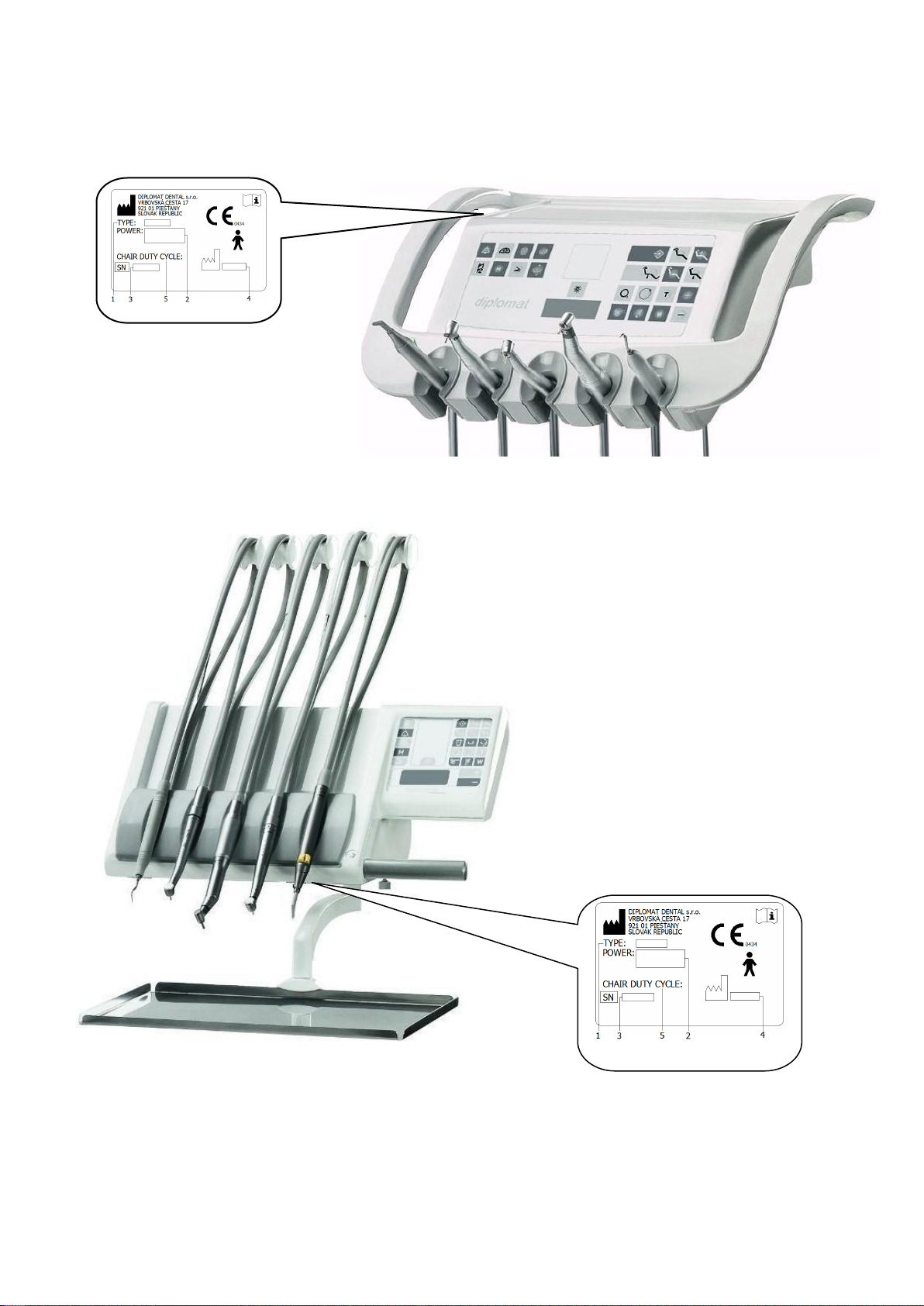
4.1 DATA PLATE ..........................................................................................................................6
5. PRE-INSTALLATION REQUIREMENTS ...............................................................................8
5.1 ENVIRONMENTAL CONDITIONS.................................................................................................8
5.2 REQUIREMENTS FOR THE INSTALLATION OF MEDIA....................................................................8
5.3 FLOOR...................................................................................................................................9
5.4 ENVIRONMENT .......................................................................................................................9
6. ASSEMBLY AND INSTALLATION........................................................................................9
7. PUTTING THE UNIT INTO OPERATION.............................................................................10
8. PRODUCT OPERATION .....................................................................................................11
8.1 CONTROL PANEL WITH INSTRUMENTS ...................................................................................11
8.1.1 Description of buttons ..................................................................................................12
8.1.2 Setting of water amount................................................................................................21
8.1.3 Button of the brake of the control panel (according the model)................................21
8.1.4 Fitting of the tray of the tray table................................................................................22
8.1.5 Operation of individual instruments ............................................................................22
8.2 FOOT CONTROLLER..............................................................................................................27
8.3 SPITTOON BLOCK................................................................................................................31
8.3.1 Assistant table...............................................................................................................32
8.3.2 Double holder................................................................................................................32
8.3.3 Equipment of the spittoon block..................................................................................33
8.4 LIGHT..................................................................................................................................33
8.5 HYGIENE..............................................................................................................................34
8.6 MANUAL CONTROL OF THE HEAD REST ..................................................................................34
8.7 MANUAL CONTROL OF THE RIGHT ARM REST .........................................................................35
8.8 COMPLETION OF WORK.........................................................................................................36
9. PRODUCT MAINTENANCE ................................................................................................36
10. CLEANING, DISINFECTION AND DECONTAMINATION.................................................37
10.1 DISINFECTION OF THE INTERNAL DISTRIBUTIONS OF THE INSTRUMENTS .................................37
10.2 DECONTAMINATION OF THE SPITTOON BOWL........................................................................37
10.3 CLEANING AND DECONTAMINATION OF THE SALIVA EJECTOR................................................37
10.4 CLEANING AND DECONTAMINATION OF THE BOG AND SMALL ASPIRATOR...............................38
11. DISPOSAL OF THE EQIPMENT........................................................................................40
12. REPAIR SERVICE.............................................................................................................40
13. CONTENT OF THE PACKAGING .....................................................................................41
14. GUARANTEE.....................................................................................................................41
INSTALLATION PLAN ............................................................................................................42
gb_da270,da280_2014_06 3/42
1. PURPOSE AND USE
These Instructions for Use describes how to use the dental units of DIPLOMAT ADEPT DA
270 and DA 280. Please read these Instructions for Use thoroughly before attempting to use
the unit. The dental unit is allowed to be operated only by the dentist who has been made
familiar with the present Instructions for Use and the dental apllications that can be done by
means of the dental unit in question. In order for you to be satisfied with the dental unit, the
following must be observed: Installation, setting and/or modifications must be made by the
qualified authorized service personnel of an organization that has licence for such activity.
Conditions for the use of media and installation given in the Instructions for use of
DIPLOMAT ADEPT DA 270 and DA 280 must be met, too.
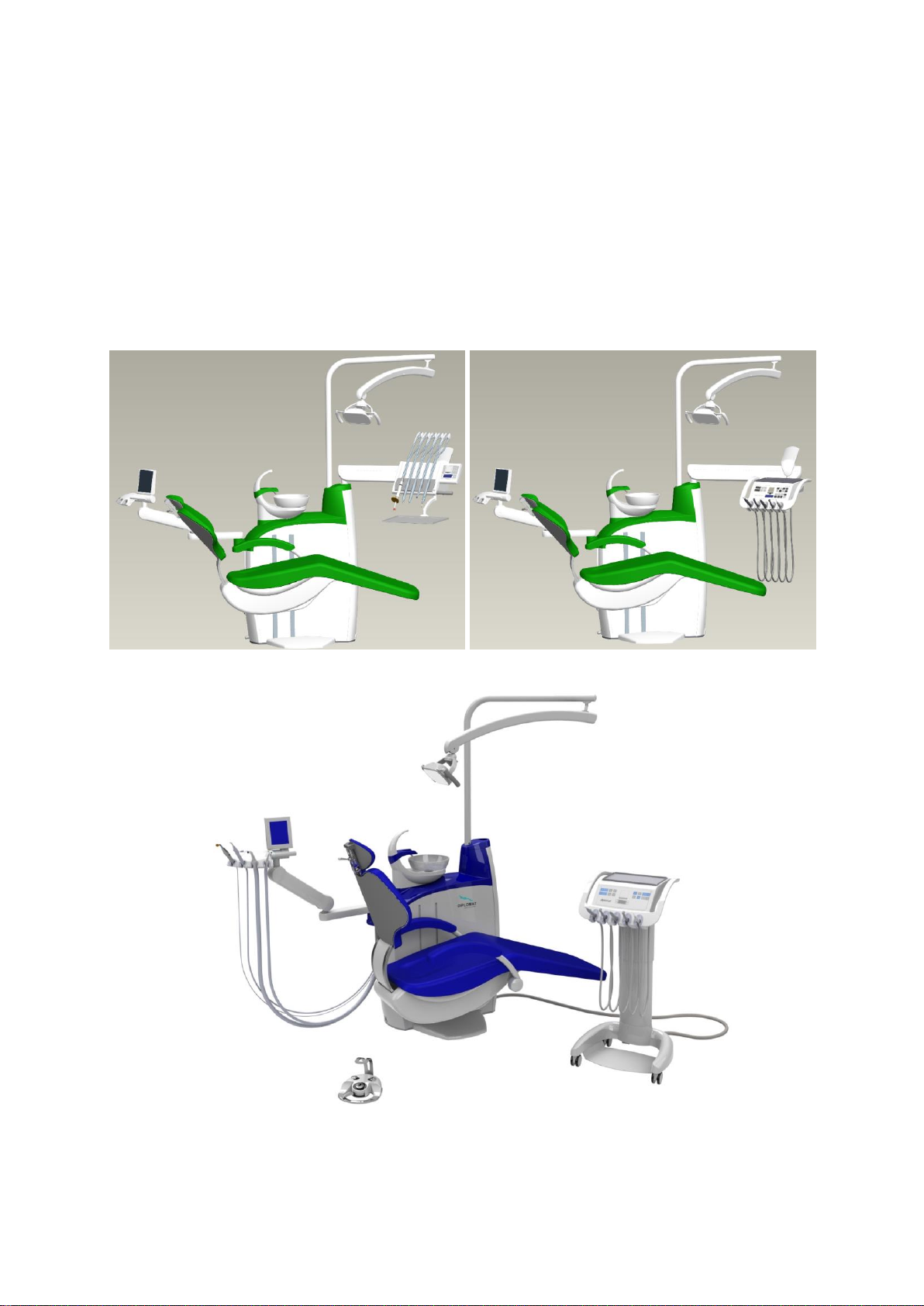
DIPLOMAT ADEPT DA 280
DIPLOMAT ADEPT DA 270
DIPLOMAT ADEPT DA 280 CART
gb_da270,da280_2014_06 4/42
2. PRODUCT DESCRIPTION
The dental unit of DIPLOMAT ADEPT DA 270 is designed as a stationary unit with a carried
chair and upper hose delivery and DIPLOMAT ADEPT DA 280 with lower hose delivery of
instruments. DIPLOMAT ADEPT DA 280 dental unit is also available in a Cart Version. Control
panel pantograph with the control panel and instruments, and light pantograph with the dental
operating light are fitted at the upper part of the bearing pillar of the spittoon block. In a special
mobile Cart Version DA280 features a cart-mounted rear delivery system. The
instruments are controlled by the foot controller, except for the syringe, big and small aspirator,
saliva ejector (and/or polymerization lamp and intraoral camera). On the face surface of the
control panel is a membrane keyboard or glass touch screen with a display and negatoscope.
The handle serves for re-positioning of the control panel. X-ray images are attached to the
negatoscope by means of a clip furnished. The spittoon block is delivered in various versions
with a saliva ejector or with an assistant arm with big and small aspirator. The spittoon bowl and
bowl flushing tube are detachable. The bowl drive is either manual or powered (according to
the requirements). Suction handpieces of the small and big aspirator are detachable, capable of
being disinfected and sterilized. Handpieces of the saliva ejector are for single use. Side table
with a side dish fixed to the arm of the light pantograph and monitor arm with LCD monitor are
installed as an option upon order. The dental unit of DIPLOMAT ADEPT DA 270, DA 280 is
always equipped on the control panel with a syringe.
The control panel can be fitted with the following instruments:
max. 4 rotary instruments
min. 1 syringe
max. 5 instruments with light
1 scaler
max. 4 turbines
1 polymerization lamp (led)
max. 4 micromotors (max. 3 DC motor,
max. 2xMX motor)
1 polisher
Note
Optional and supplementary equipment (see the valid price list).
3. TECHNICAL DATA
Supply voltage
230V ± 10%
Frequency
50 Hz ± 2 %
Max. power input at 230V/50 Hz
1550 VA + 10%
Input pressure of air
from 0,45 to 0,8 MPa
Input pressure of water
from 0,3 to 0,6 MPa
Dental unit weight
210 kg + max.35 kg acc.to version
Type of protection against electric shock
Class I equipment
Degree of protection against electric shock
applied parts of B type
Temperature of water for the cup
36±5 °C (with heater fitted)
Max. loading capacity of the tray table
1,5 kg
Max. loading capacity of the side table
3 kg
Operation mode
continuous with intermittent loading,
corresponding to the common dental practice.
Chair
Range of the height of the seat above the floor
397 ÷ 825 mm 15 mm
Range of the tilting of the back rest from vertical plane
20°÷ 90° 2°
Vertical movement time
max. 20 sec
Back rest movement time
max. 18 sec
Maximum loading capacity of the chair (EN ISO 6875)
max. 200 kg
Type of operation
1 : 16 (cycle, e.g.25s run, 400s rest)
Sound pressure level of the chair
max. 54 dB
gb_da270,da280_2014_06 5/42
Caution
To eliminate the risk of electric shock, the present equipment must be connected to the supply
mains with protective earthing.
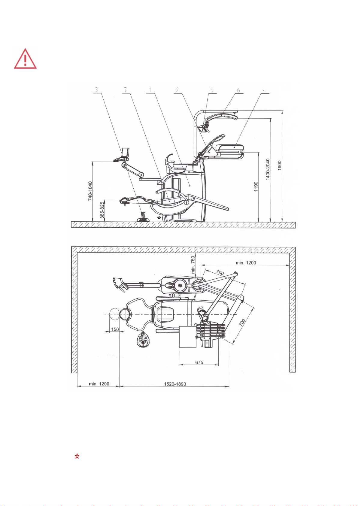
4. DESCRIPTION OF THE DENTAL UNIT
1.Spittoon block with assistant arm
2.Control panel
3.Foot controller
4.Pantograph of the control panel
5.Dental operating light
6.Pantograph of the light
7.Dental chair
main switch, located onthe outer side of the spittoon block
gb_da270,da280_2014_06 6/42
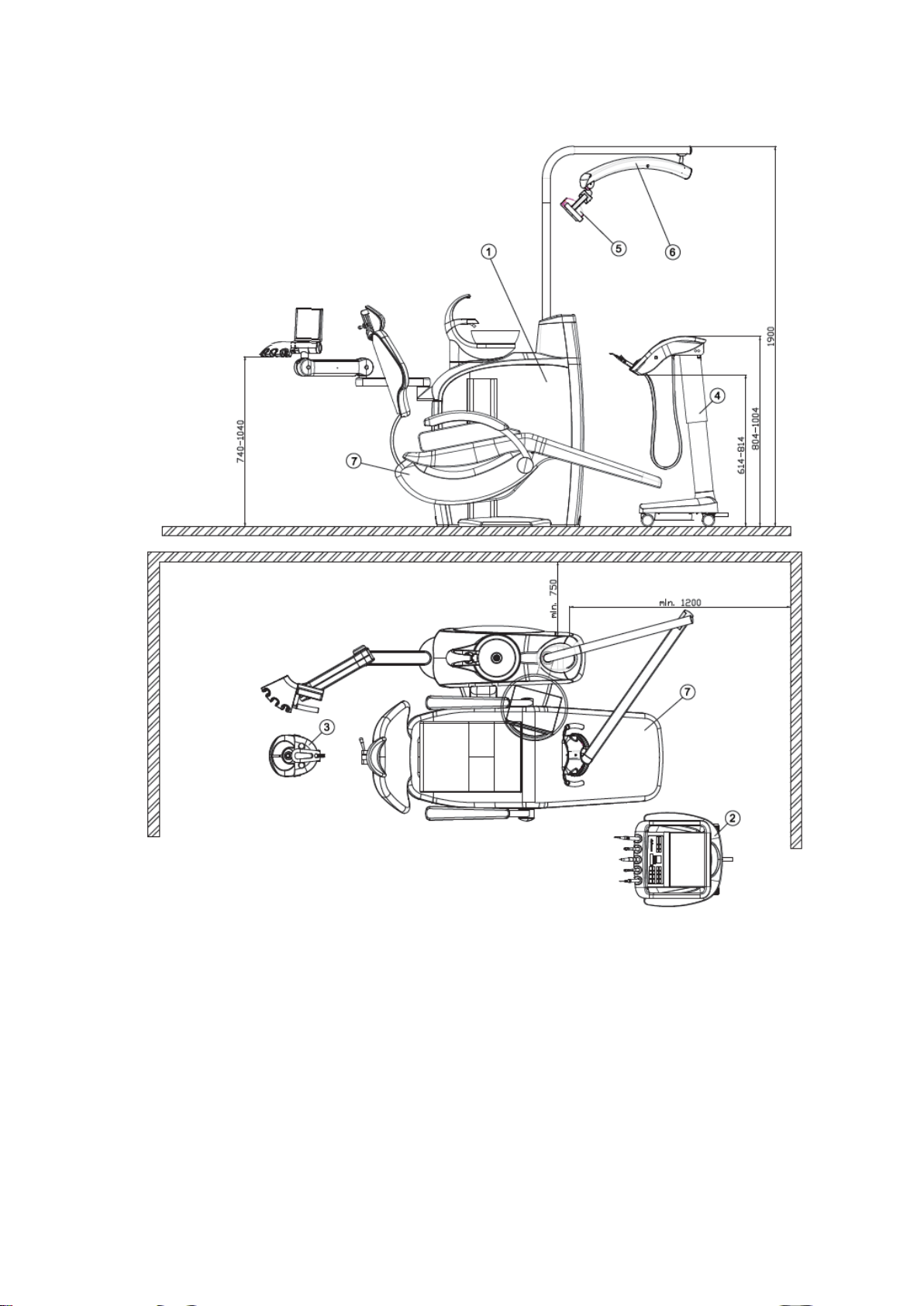
DESCRIPTION OF THE DENTAL UNIT DA 280 CART
1.Spittoon block with assistant arm
2.Control panel
3.Foot controller
4.Cart
5.Dental operating light
6.Pantograph of the light
7.Dental chair
gb_da270,da280_2014_06 7/42
4.1 Data plate
1 –designation of the unit type
2 –basic electrical parameters
3 –serial number
4 –production date
5 –chair operation type

gb_da270,da280_2014_06 8/42
5. PRE-INSTALLATION REQUIREMENTS
5.1 Environmental conditions
Not to be installed in the premises with explosion hazard!
5.2 Requirements for the installation of media
Water
Drinkable water with input pressure of 0,3 MPa to 0,6 MPa with the flowrate of min.4 l/min.,
without particles bigger than 50 µm, which might clog the small cross sections of the pipes of
the dental unit, must be used. If the water contains particles bigger than 50 µm, there must be
introduced 50 µm advance filter /strainer.
Cooling of the instruments with water from the central distribution
There must be introduced advance 5 µm filter.If the water contains more than 50 mg CaO/l,
or 36 mg MgO/l, there must be introduced water treatment device connected to the input of the
water distribution. Hard water may even cause the unit not to function. Water treatment device
is introduced if distilled water is not used. The distribution after the filter must be made of Cu,
and/or PE tube. A suitable certified closing valve must be introduced into the central distribution
of water for the unit! In installation it is necessary to install a device to prevent the backflow at
the point of the connection to the supply of municipal tap water. The said device is not part of
the dental unit.
Air
Supply of at least 55 l/min. of air at the pressure of 0,45 to 0,8 MPa, oilless, clean and dry,
must be ensured. Tubes made of Cu and/or PE are recommended.
Suction ( in the event of the version of the spittoon block with big and small
aspirator)
Static vacuum must be within the range of min. 0,005 MPa (50 mbar) to max. 0,02 MPa (200
mbar), measured at the installed position. When the static vacuum is higher than 0,02 MPa,
a suction calibration (regulating) valve should be introduced in the suction branch to restrict the
max. vacuum to 0,02 MPa. The said regulating valve is not part of the dental unit. The suction
unit must produce the flowrate of at least 450l/min., measured at the installed position.
Waste
The waste /drain/ branch must have continuous slope of min. 1% with minimum flowrate of
10l/min. and must be free of sharp bends and conditions that might cause backflow. Do not
use the same waste branch with another dental unit or a basin! It is allowed to use tubes
made of polypropylene or cured polyethylene.
Caution
Pre-installation and installation must be performed according to the applicable standards of the
particular country and in accordance with the valid documentation of the manufacturer, which is
owned by each authorized representative of Diplomat Dental s.r.o.
Note
If the regulations of the country in which the installation is carried out require an amalgam
catcher, the dental unit with the spittoon block without the amalgam catcher must be connected

gb_da270,da280_2014_06 9/42
to an external amalgam catcher. Installation of the external amalgam catcher must be carried
out according to the instruction of its manufacturer!
Recommended mains fuse rating
Recommended rating of the fuse of the supply main is 16A (in the event of circuit breaker –
circuit breaker with switching-off characteristic of C type). No other equipment should be
connected to the supply main in question! Max. power input of the dental unit is 1550 VA. The
supply main must comply with the respective national standard.
Recommendation
Unless national standard stipulates otherwise, the manufacturer recommends to use current
protective switch with the sensitivity of 30mA and instantaneous time of switching-off.
Pre-installation requirements having been met, assembly and installation of the dental unit is
carried out and it is connected to the media.
5.3 Floor
The floor must have a concrete foundation of at least 100mm thickness. The slope of the floor
shall not exceed 1%. The use of antistatic floor is recommended.
5.4 Environment
ambient temperature range from +10°C +40°C
relative humidity range from 30% 75 %
atmospheric pressure range from 700 hPa 1060 hPa
6. ASSEMBLY AND INSTALLATION
Unpacking of the unit and inspection of the delivery
Inspect the transport packages for damage. If a defect of the transport package is found, do not
open the consignment, and report the defect to the forwarding agent or seller immediately. If the
consignment is intact, carefully open the package and unpack individual parts of the dental unit.
Check the completness of the delivery according to the Packing List. If the unit is equipped
with a glass keyboard, take care of its glass surface in handling.
The installation must be carried out by a service technician with valid certificate, otherwise
potential guarantee shall not be accepted. The guarantee form must be completed and sent to
the manufacturer or the seller.
Note:
Sieves (packed with small parts) are to be inserted in the tips of the aspirators according to
Fig.10.1. (chapter 10.4)
to
to
to
gb_da270,da280_2014_06 10/42
7. PUTTING THE UNIT INTO OPERATION
1. switch on the compressor and let it get pressurized
2. open the central water supply
3. turn on the suction unit (if the spittoon block is fitted with the big and small aspirator)
4. turn on the main switch located on the cover of the spittoon block –position I, the indicator
light of the main switch goes on. The following message is displayed:
Thus indicating the readiness of the unit for operation. The unit is connected to the distribution
of water and air. After approx. 5s the unit is ready to work. If the dental unit is equipped with
electrical water heater, it is necessary to wait for approx. 10 min. for the water to be warmed up
to the desired temperature. In turning the unit on, no instruments should be taken, the foot
controller should be in the rest position and the buttons of the keyboards should not be
depressed.
Caution
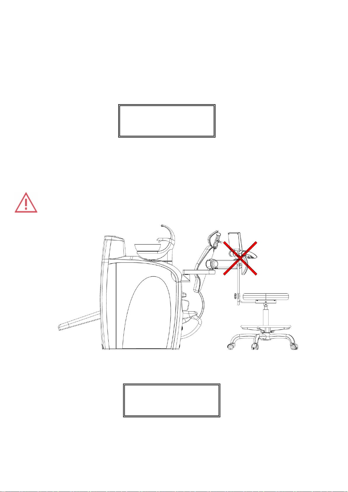
When moving the chair, the arm and the assistant table must not be in the trajectory of the
chair. (see the illustration).
Besides the saliva ejector, small and big aspirator –according to the version –polymerization
lamp and the syringe (on the control panel) only one instrument can be used (taken)
simultaneously! Not observing of the condition above is indicated on the display by the following
message:
DENTAL UNIT V1
READY FOR WORK
DENTAL UNIT V1
INSTRUMENT ERROR
gb_da270,da280_2014_06 11/42
8. PRODUCT OPERATION
8.1 Control panel with instruments
Note
The display is legible in each working position of the dentist (both sitting and standing).
In the event of the glass keyboard, after pressing the button it is active for ca 10 seconds –
indicated by means of the indicator of the pressing of the button on the display.
Programming of the time of the cup filling and bowl flushing in the event of the glass keyboard
for more than 10 s is possible only by means of the foot controller or by means of the buttons
on the assistant table.
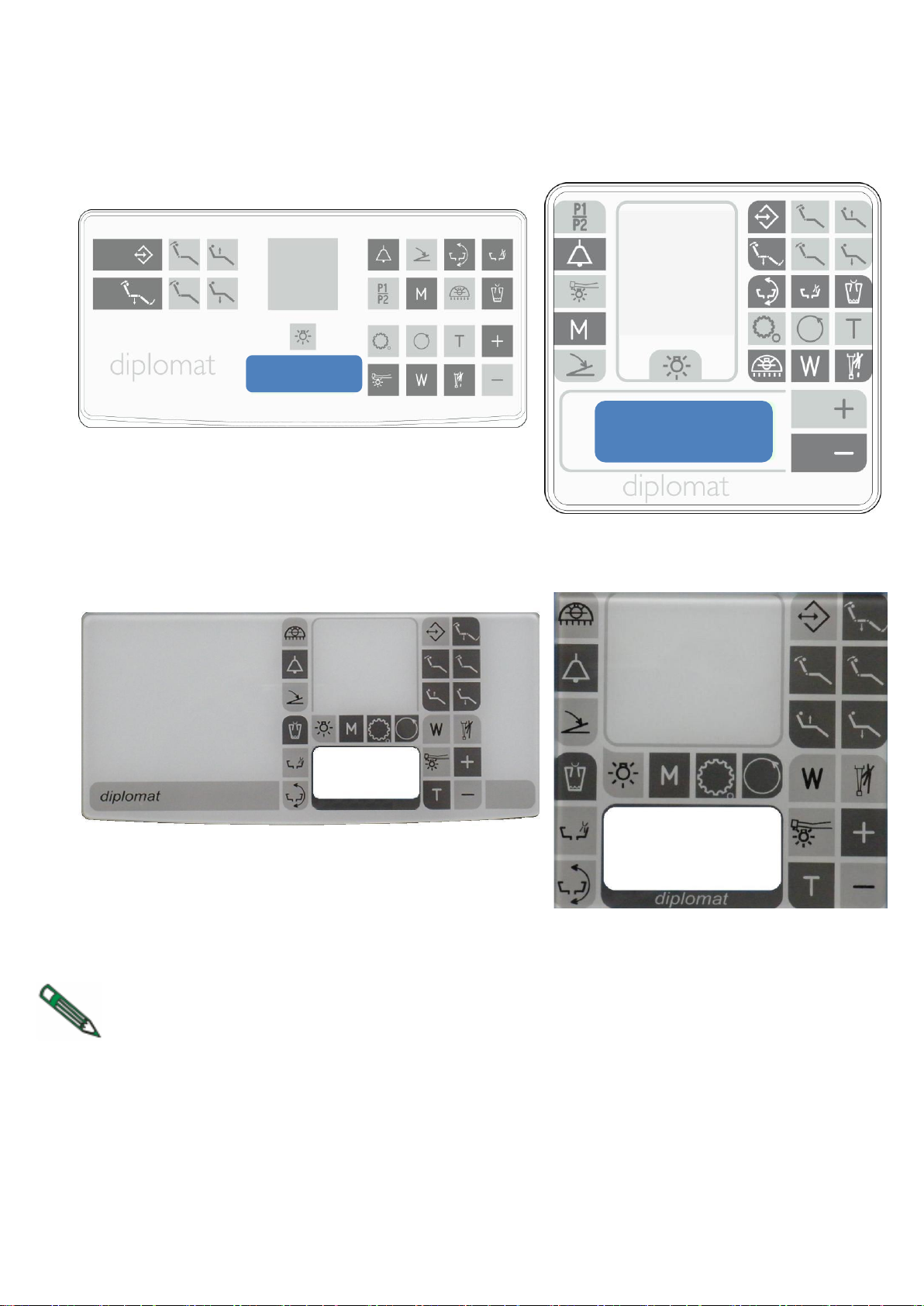
Membrane keyboard
Membrane keyboard
Glass keyboard
Glass keyboard
gb_da270,da280_2014_06 12/42
Button
Description
Button
Description
Button
Description
negatoscope
illumination
setting of the amount
of cooling water
rotation of the spittoon bowl
(only for el. control)
instrument cooling
changing-over of the
program sets
switch to move the chair up
reversing of the
rotations of the
micromotor,ENDO,
AFT
main light control
(valid for particular
type)
switch to move the chair
down
cup filling
supplementary button
(e.g.door opening)
(valid for particular type)
switch to move the rest
forward
spittoon bowl
flushing
selection of activity
mode for MX motor
and torque for motor
switch to move the rest
backward
illumination of
instruments
setting of torque for
micromotor
writing-in and recalling of
program positions
button to increase
parameters
changing-over of the
function of the foot
controller (analogue -
ON/OFF)
automatic setting of the
starting (getting-on) position
button to decrease
parameters
change of the
transmission ratio of
the instrument head
8.1.1 Description of the buttons
To activate a function, it is enough just to press (with the membrane keyboard) and/or touch
(with the glass keyboard) at the point of selected button. With the glass keyboard, the selection
of chosen function is indicated in addition to the display also by a short beep and a dot on the
display. For all controllable parameters, their informative values is represented by means of
a bar indicator in the lower part of the display (valid only for the glass keyboard). Maximum of
the bar corresponds to 100% of the set value. Maximum time of the selection of any symbol is
ca 10 sec. After the said time has elapsed, a condition is achieved as if the function was not
selected.
Locking and unlocking of the keyboard (valid only for the glass keyboard)
Locking of the keyboard –simultaneous selection of the button and the button . Key
symbol is displayed and the keyboard keys do not respond to the selection of buttons.
Unlocking of the keyboard –simultaneously select the buttons and again.
Note
Always lock the keyboard before cleaning the keyboard while the dental unit is turned on. After
the keyboard has been cleaned, it is necessary to unlock the keyboard, because the
instruments are locked too.
gb_da270,da280_2014_06 13/42
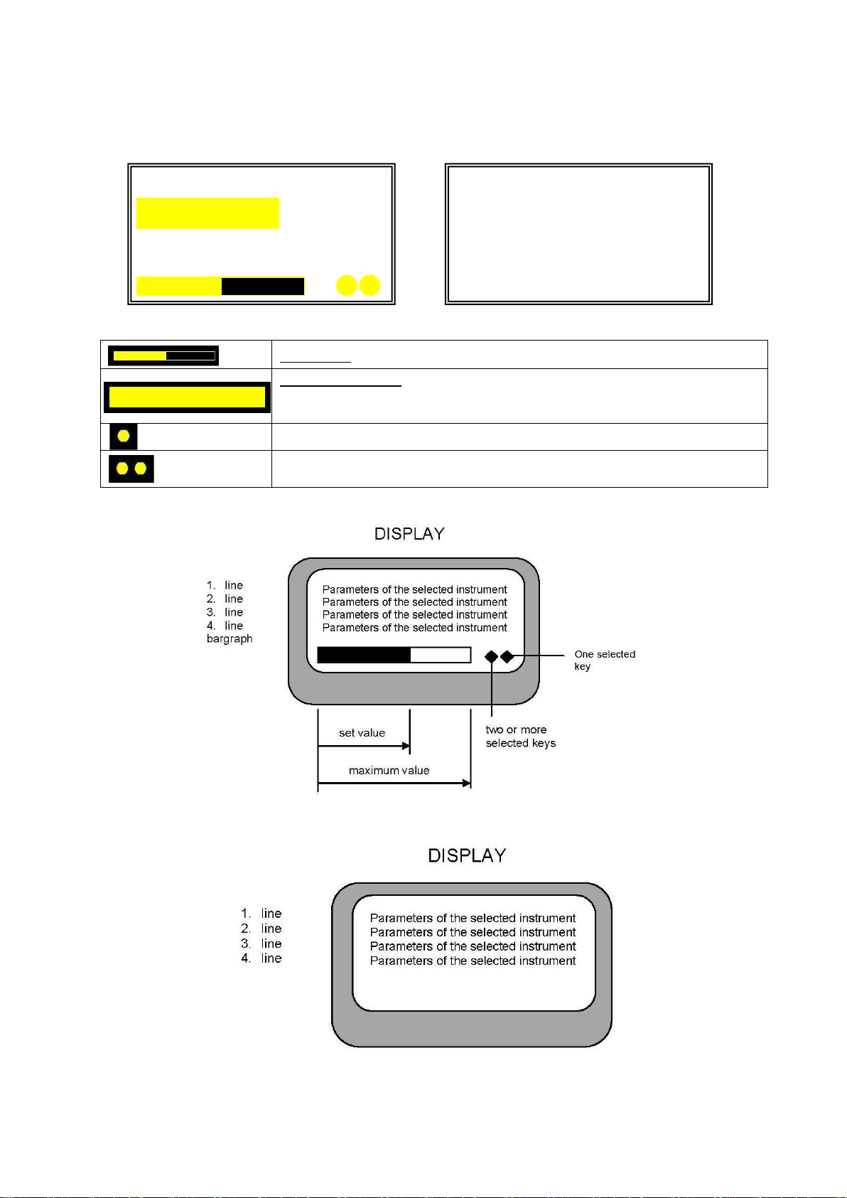
Representations on the display
Glass keyboard Membrane keyboard
Description of the data of the display–glass keyboard
Status bar –graphical representation of highlighted value
Highlighted value –active value that is currently set and which can
be changed by means of the buttons PLUS (increase) or MINUS
(decrease)
Indicator of the selection of a button („pressing“ of one key)
Indicator of the selection of arbitrary buttons („pressing“ of two and
more keys)
Membrane keyboard
Glass keyboard
N = 100000RPM
M3X N W A
T= 0 , 300Ncm R = 1 : 5
N = 100000RPM
50 , 00%
M3X N W A
T= 0 , 300Ncm R = 1 : 5
N = 100000RPM
50 , 00%
gb_da270,da280_2014_06 14/42
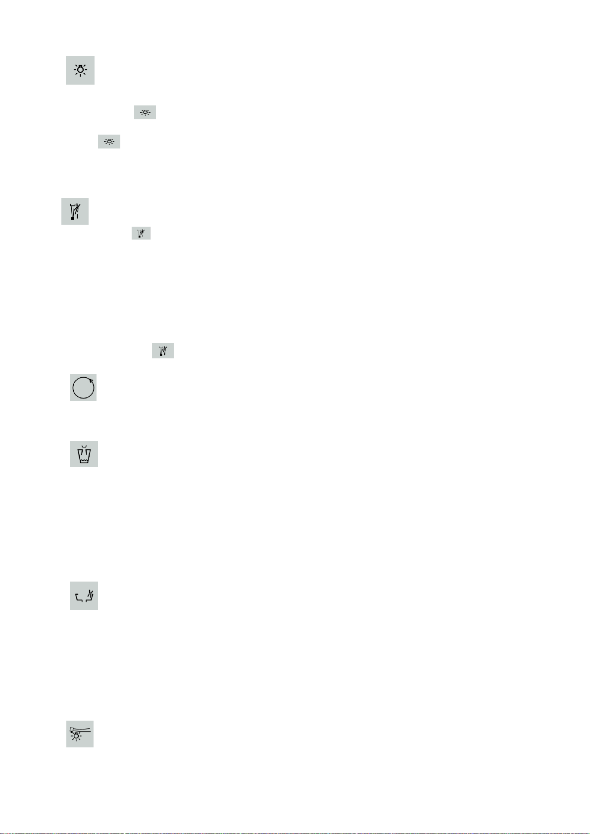
Press (touch) the button to turn the negatoscope illumination on. To turn the illumination
off, press (touch) it again. To control the intensity of the negatoscope, press (touch) the
button and the buttons PLUS and MINUS simultaneously with the negatoscope
turned on. After the negatoscope has been turned on, by keeping the finger on the button
for more than 4s the brightness of the negatoscope is increased up to maximum.
After the maximum brightness has been achieved, the brightness decreases to minimum
and then increases gradually. The set values of brightness are stored in the memory and
set automatically when the negatoscope illumination has been turned on again.
It is possible to switch the instrument cooling on by means of pressing (touching) the
button for micromotor and turbine, while the switched-on condition is indicated on the
display by going the symbol "S" or "W" on. When the instrument has been returned to the
basic position, the current setting of the instrument cooling is saved automatically.
Changing-over of the cooling mode in the event of the glass keyboard, see Cl. 8.2 –
SPRAY button.
The following 2 conditions of cooling are available:
"S" - spray cooling
"W" - water cooling
To change-over between the mode of cooling with water (W) and spray (S), press (touch)
the button for more than 10s and less than 16s. If the glass keyboard is used, the
cooling modes are changed-over by means of the spray button on the foot controller.
It serves to change the direction of the revolutions of the micromotor, to set the ENDO
function for the ultrasonic scaler and to set AFT (auto-forward time) for MX micromotor.
To let the patient cup fill for the set time, press (touch) the button and keep the finger on it
for more than 0,6s. To set the filling time up to the moment the button has been released,
press (touch) and keep the finger on the button for more than 4s. To interrupt the cup
filling during the cup filling time, press (touch) the button for min. 0,2s. Maximum
programmed cup filling time is 25s. The set cup filling time is saved automatically and with
repeated pressing (touching) shorter than 4 s the cup filling is started for the set time.
In the event of the glass keyboard, the programming of the cup filling time for more than
10s is possible only from the foot controller or by means of the button on the assistant
table.
To start the flushing of the spittoon bowl for the set time, press (touch) the button and
keep the finger on it for more than 0,6s. To set the spittoon bowl flushing time up to the
moment the button has been released, press (touch) and keep the finger on the button for
more than 4s. To interrupt the bowl flushing during the bowl flushing time, press (touch)
the button for min. 0,2s. Max. programmed bowl flushing time is 40s.
Programming of the time of the bowl flushing in the event of the glass keyboard for more
than 10 s is possible only by means of the foot controller or by means of the button on the
assistant table.
Instrument cooling
Reversing of the rotation of the micromotor
Cup filling
Bowl flushing
Illumination of instruments
Negatoscope illumination
gb_da270,da280_2014_06 15/42
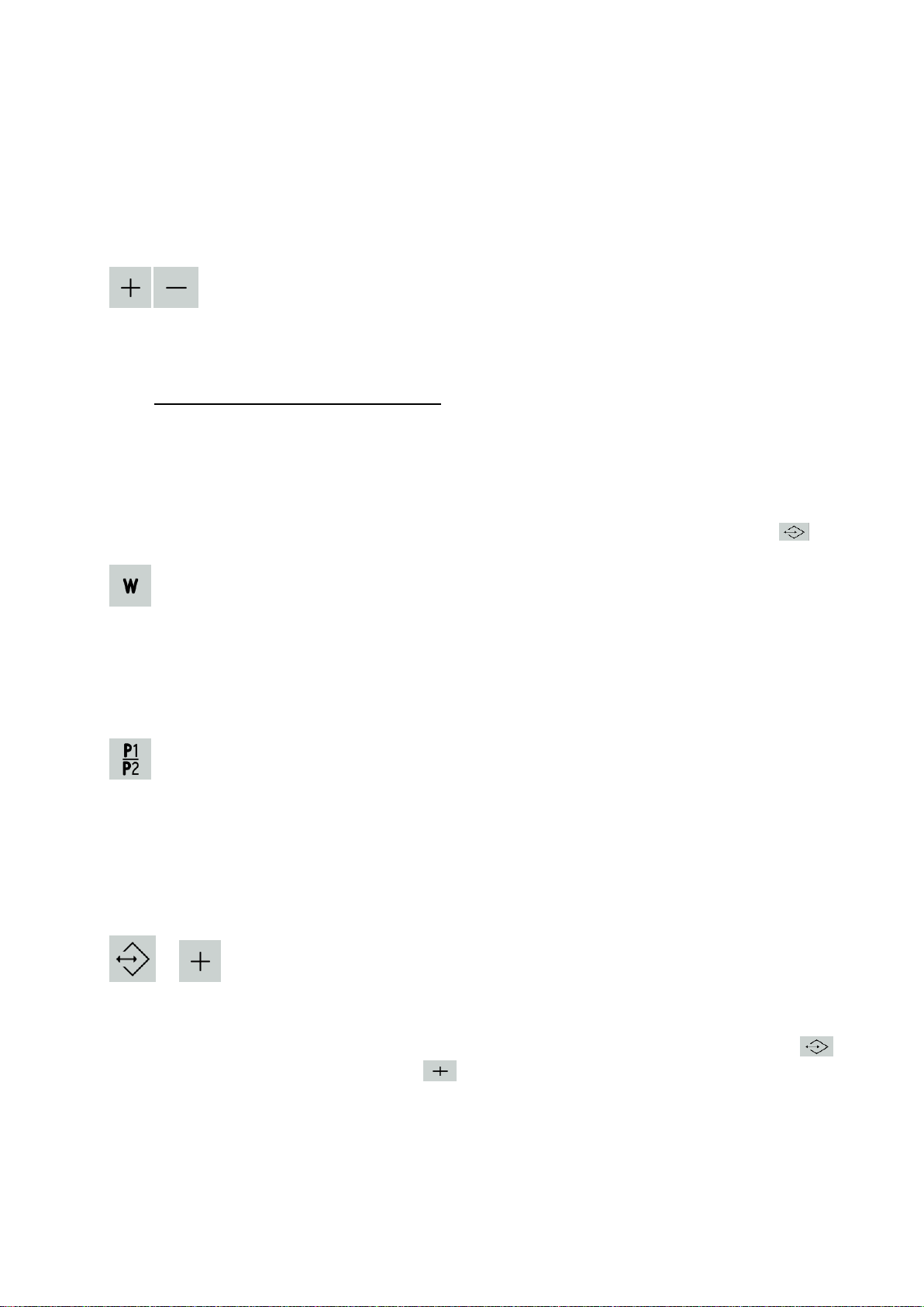
Plus and minus
Press (touch) the button to turn the illumination of the rotary instruments (turbine,
micromotor) on and off. By pressing (touching) it is possible to modify the instrument that
has been taken. When the instrument illumination is turned on, "L" is displayed. The
instrument illumination goes on after putting the instrument into operation. The instrument
illumination goes off automatically after 10s has elapsed after the end of the use of the
instrument. After the instrument has been replaced to the basic position, the instrument
illumination goes off.
To increase (decrease) the parameter being set from min. up to max. value, press (touch)
the button for a short time. By pressing (touching) and holding the button for 1s, the
parameter in question is increased (decreased) up to the maximum (minimum) value.
The buttons serve to set the following:
the micromotor revolutions (speed)
the output when the scaler is used
negatoscope illuminance /illumination intensity/, with the negatoscope turned on
main light illuminance
flowrate of cooling water for instruments, except for the syringe
the torque for MX motor
changing-over of the program position P1...P8 in the combination with the button for
the glass keyboard
Depending on the version of the dental unit, it is possible to adjust the flowrate of cooling
water, see Cl. 8.1.2. If the unit is not equipped with the proportional valve, then (W) is not
displayed.
The button serves to select the programs. Each instrument has the option of 8 programs
P1–P8.
The selection of P1 –P8 programs is made by pressing the button P1/P2 on the dentist
control panel when the instrument is taken, while the current program is displayed in the
left lower corner.
In each program it is possible to make any changes and these changes are saved
automatically.
+
The button (combination of buttons) serves to select the programs. Each instrument has
the option of 8 programs P1–P8.
The selection of the P1 –P8 programs is made by touching and holding the button
and subsequent repeated touching in case of the glass keyboard –it is necessary to
observe the sequence of pressing the buttons on the dentist control panel with the
instrument taken, while the current program is displayed in the left lower corner.
Water
P1/P8 –programming of the instruments (membrane keyboard)
Programming of the instruments (glass keyboard)
gb_da270,da280_2014_06 16/42
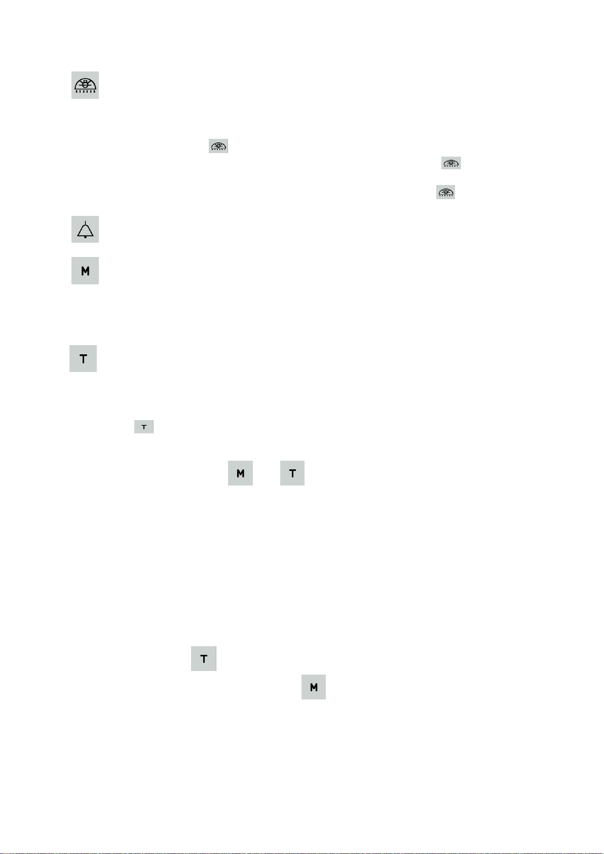
The button serves to control the main dental light. Press (touch) the button to change-over
between the three conditions –lower illuminance, higher illuminance, light turned off. At
the higher illuminance it is possible to control the illuminance by simultaneous pressing
(touching) the button and the buttons PLUS or MINUS, namely so that in changing-
over from the lower illuminance to the higher, keep the finger on and increase or
decrease the illuminance of the dental light by means of the buttons PLUS or MINUS. It is
also possible to control the illuminance by keeping the finger on for more than 4s
when changed-over to the higher illuminance.
Acoustic indication is heard while the button is kept pressed (touched).
The button serves for the selection of the mode of activity for the MX micromotor, while
the selected mode is displayed: "MX N" –normal mode of activity, "MX R" - auto-reverse
mode, "MX F" - auto-forward mode. To change-over the torque for the brush motor, press
the button T and then press the button M (description, see the button T).
Setting of the limit torque for the MX motor. Press (touch) the button and then set the limit
torque by means of PLUS, MINUS. The mode of the setting of the limit torque is indicated
by means of the symbol "!" next to the symbol "T" ("T!xxx, xxxNcm"). With the glass
keyboard, the set value is highlighted. To finish the setting of the torque, press (touch) the
button again, the message "T=xxx,xxxNcm" is displayed.
New functions for brush micromotors
By means of the buttons and it is possible to change the torque of the brush
micromotors M1, M2 and M3.
In the left upper corner the following is displayed on the dentist control panel after the
micromotor M1, M2 and M3 has been taken:
M1 or M2 or M3
and then the following is displayed:
FL or FM or FH
FL ( Force Low) represents 80% value of the maximum torque
FM (Force Medium) represents 90% value of the maximum torque
FH ( Force High) represents 100% value of the maximum torque
Press the button on the dentist control panel and then change the value of the
maximum torque by pressing the button , while the message on the display changes
in the following sequence: FL, FM, FH and again FL.
The change can be made provided an instrument is taken and START function on the foot
controller is inactive. Changes are saved in the programs P1-P8 automatically.
Control of the main light (according to the version of the dental unit)
Button according to the version of the dental unit (e.g. door opening)
Selection of the mode of activity for brushless (MX) and brush (MC2, MC3)
motor motor
Setting of the torque for the motor
gb_da270,da280_2014_06 17/42
The button serves to change-over the mode of the foot controller. It is possible to change-
over between the mode of the proportional control and the "on /off" mode ( O/A on the
display).
By touching the button it is possible to choose one of the following transmission ratios:
1:5,1:2, 2:3, 1:1, 2:1, 3:1, 4:1, 5:1, 8:1, 10:1, 16:1, 20:1, 32:1, 64:1, 128:1. It does not
change the revolutions, only re-calculates the current value of the revolutions at the tip.
Chair movement
All the buttons below controls the chair directly with the instrument replaced or taken
when the foot controller pedal is in the zero position.
seat up seat down back rest backward back rest forward
Saving / recalling of a macro into / from the memory.
It serves to save and recall pre-set positions of the chair.
With the glass keyboard, the button, as the only one, responds only after it has
been released and not immediately after touching it as others do! If the button needs to
be held in case of the glass keyboard, it is necessary to use the identical button on the
foot controller.
Selection of memory group.
Programable positions of the chair can be saved in two groups (2x5 positions).
Procedure how to select the desired set:
Hold the button (ca 3 seconds) until you hear an audio signal (short –long tone).
Only then the unit switches to the programming mode. Immediately after you have heard the
audio signal, press the button of the selection of the group in question.
For group 1 it is the button .
For group 2 it is the button .
The selection of the group is indicated by means of an audio signal –1 beep for group 1
and 2 beeps for group 2. The selection of the group remains saved in the memory even after
the unit has been turned off.
How to save the chair position into the memory:
Get the chair to the desired position and press the combination of the buttons one by one
+ + one of the buttons under which the position is to be saved:
, , , .
Changing-over of the function of the foot controller (analogue - ON/OFF)
Change of the transmission ratio of the instrument head
gb_da270,da280_2014_06 18/42
The button should be held (ca 3 seconds) until you hear an audio signal (short –
long tone). Only then the unit switches to the programming mode and it is possible to go on
programming. Otherwise the new data on the position will not be saved into the memory.
With the glass keyboard it is necessary to use the button from the foot controller.
Saving of the position is indicated by means of an audio signal –one long and two short
beeps.
If the writing-in fails, you will hear an audio signal –3 long beeps.
How to recall the chair position from the memory:
Press the combination below one by one
+ one of the buttons under which the position of the chair is saved.
Getting-on position
If all the instruments are replaced and the button is pressed (touched), the chair is set
automatically to the getting on/off position. At the same time, the main light goes off, the bowl is
returned to the basic position and flushed automatically (if powered bowl rotation and light
control is fitted). If an instrument is taken, only getting-on position is recalled.
Programming of the getting-on position:
The procedure is identical with that of programming any other position of the chair, i.e.
pressing the button combination below one by one
+ + .
The button should be held (ca 3 seconds) until you hear an audio signal (short –
long tone). Only then the unit switches to the programming mode and it is possible to go on
programming. Otherwise the new data on the position will not be saved into the memory.
With the glass keyboard it is necessary to use the button from the foot controller.
Saving of the position is indicated by means of an audio signal –one long and two short
beeps.
If the writing-in fails, you will hear an audio signal –3 long beeps.
To recall the getting-on position, simply press the button .
In the event that there might be a collision of the bowl and the chair, the chair is blocked
and an audio signal sounds–short repeated tone. To finish the movement of the chair it is
necessary to return the bowl to the basic position manually.
Rinsing position
By pressing the button for more than 1s and less than 4s the chair returns from the
rinsing position, while the bowl starts to rotate to the basic position, where it stops and at the
same time bowl flushing is carried out according to the programmed time. After pressing the
button, there is a short beep and after the time interval of more than 1s and less than 4s there is
a long beep.
By pressing the button for more than 4s the rinsing position of the chair is recalled and the bowl
starts to rotate towards the patient where it stops.
gb_da270,da280_2014_06 19/42
After the button has been pressed, there is a short beep and after a time interval of
more than 1s and less than 4s there is a long beep. After a time interval of more than 4s there is
a triple beep.
The chair should be pre-programmed so that the rinsing position is saved under the button for
seat down movement.
After the rinsing position of the chair has been recalled by means of the button for bowl rotation,
the chair should not be handled in any other way in order for the return from the rinsing position
of the chair recalled by means of the bowl rotation button to work properly.
For the rinsing position to function correctly it is necessary - while setting the said
position - to observe the safety height of the chair preventing the collision of the chair
and bowl while maintaining the patient safety. When the said condition is not observed,
the chair movement while the bowl is deflected is blocked to avoid injury to the patient
arm and/or the collision of the chair and bowl.
This occurs also at moving to the rinsing position from the position above the safety
height of the chair. If that is the case, the recalling of the rinsing position is unusable for
safety reasons.
How to set the rinsing position:
- lower the chair to the lower position
- put the bowl out
- by pressing and holding the button move the chair up until it stops automatically
- move the chair down by ca 2cm
- set the back rest position
- save the set position as the rinsing position under the respective button, i.e. the combination of
buttons
+ + .
Test of the setting of the rinsing position
Move the chair to the lower position.
Recall the rinsing position.
The bowl must be put out and the chair must move to the rinsing position.
Recall the return from the rinsing position.
The bowl must retract and the chair must move to the previous position.
Automatic bowl control applies only for powered bowl drive. In the event that the unit is not fitted
with powered bowl rotation and there might be a collision of the bowl and the chair, the chair is
blocked and an audible signal sounds - short repeated tone. To finish the movement of the
chair it is necessary to return the bowl to the basic position manually.
Caution
The button is active for approx. 4 seconds after pressing, i.e. within the said time the
second button from the required combination should be pressed, depending on the desired
function. After the said time has elapsed, the function is cancelled and the button must
be pressed again to recall it.

gb_da270,da280_2014_06 20/42
For the movement of the chair in the upper half of the trajectory it is necessary that the
bowl be in the basic position.
If that is not the case, then the chair movement is blocked and this is indicated by three long
beeps and an error message: „O“on the display of the chair control electronics in the spittoon
block. The movement of the chair to the programmed position is also blocked, if the said
position requires the movement of the chair in the upper half of the trajectory and the bowl is not
in the basic position. If that is the case, the blocking is indicated by an audio signal - short
repeated tone –until the bowl has been moved away to the basic position. Afterward the chair
continues in moving to the desired position.
If- during the movement of the chair in the upper half of the trajectory –the bowl is deflected,
then the chair stops! If that is the case, the blocking is indicated by an audio signal: long –long
–long tone. Return the bowl to the zero position and then repeat the command for the chair
movement.
When the chair hits an obstacle, the movement of the chair is stopped and changed-over to the
opposite direction (the reverse movement may not always occur when the back rest hits an
obstacle).
The said opposite movement lasts until the safety emergency switch has been released by
moving the chair away from the obstacle and/or until the chair has reached the end position in
the event that the safety switch has not been released. During such movement an alarm audio
signal sounds –long repeated tone. The following is monitored: movement of the chair
downwards, movement of the back rest backwards, bumping into the assistant table upwards. If
the chair hits the assitant table, the chair stops. If that is the case, the reverse movement does
not occur.
The manufacturer recommends to move the assistant table out of the chair trajectory
before moving the chair to avoid the collision of the chair with the assistant table and/or
damage to the assistant table.
When handling the chair, in case of a failure the information on the current failure is displayed
on the display of the chair control electronics in the spittoon block.
List and meaning of error messages on the display of the chair control electronics:
„O“ –blocking of the chair movement with the instrument running / the chair hits the instrument
holder on the assistant table
„o“ - blocking of the chair with safety switches in the chair –the chair hits an obstacle
„O.“–blocking of the chair when the bowl is moved and crosses the chair trajectory
„1.“ - error of the check of the content of EEPROM memory with the saved chair positions
„2.“ - faulty writing-in of a chair position into the EEPROM memory
„3.“ - motor1 is started but the potentiometer1 has not recorded any movement = defective
motor or potentiometer
„4.“ - motor2 je is started but the potentiometer2 has not recorded any movement = defective
motor or potentiometer
„5.“ - motor3 is started but the potentiometer3 has not recorde any movement = defective motor
or potentiometer
„6.“ - potentiometer1 is outside the working range –if the error reoccurs, perform
„AUTOSET“
„7.“ - potentiometer2 is outside the working range –if the error reoccurs, perform
„AUTOSET“
„8.“ - potentiometer3 is outside the working range –if the error reoccurs, perform
„AUTOSET“
„6“ - potentiometer1 –error of connection : short-circuited, disconnected or misconnected
wires –value outside the permissible limit
„7“ - potentiometer2 –error of connection : short-circuited, disconnected or misconnected
Other manuals for ADEPT DA 270
1
This manual suits for next models
1
Table of contents
Other Diplomat Dental Equipment manuals


